
Knee brace connection design to AISC 360 covers two joints. At the brace end, you check the bolts between the brace and the gusset plate for slip, cojinete y desgarro, then block shear and tension rupture of both parts, and tension and buckling of the gusset on its Whitmore section. en la columna, you resolve the brace force at the column face, then check the gusset-to-column fillet welds, the gusset in shear and tension along that edge, and the column web under the concentrated force.
Esta página funciona con un ejemplo real de principio a fin.. An L4x4x1/2 knee brace at 45° carries 100 saltar en tensión y 100 salto en compresión (LRFD). It is bolted with four 1 in A490-SC bolts to a 1/2 en grado A572 50 gusset plate, which is welded to the flange of a W14x90 column with 3/16 in fillets on both sides. The design is to AISC 360-16 y el Manual AISC 15ª edición. Cada ecuación está escrita con sus números., en el mismo orden que la hoja de cálculo AISC que el SkyCiv Connection Design El módulo produce para esta conexión..
What is a knee brace connection?
A knee brace is a short diagonal member that runs from a column to a beam or rafter a little way from the joint between them. It stiffens the corner of a frame and shortens the unbraced length of the members it ties together. Each end of the brace needs a connection, and this example designs the column end: the brace is bolted to a gusset plate, and the gusset is shop welded to the column flange.
The gusset is attached to the column along one edge only, which sets it apart from the corner gusset at a beam-column joint in a concentrically braced frame. Puedes comprobar este ejemplo directamente en el calculadora de conexión de rodillera. The same gusset checks appear in the vertical bracing connection calculator y el chevron brace connection calculator.
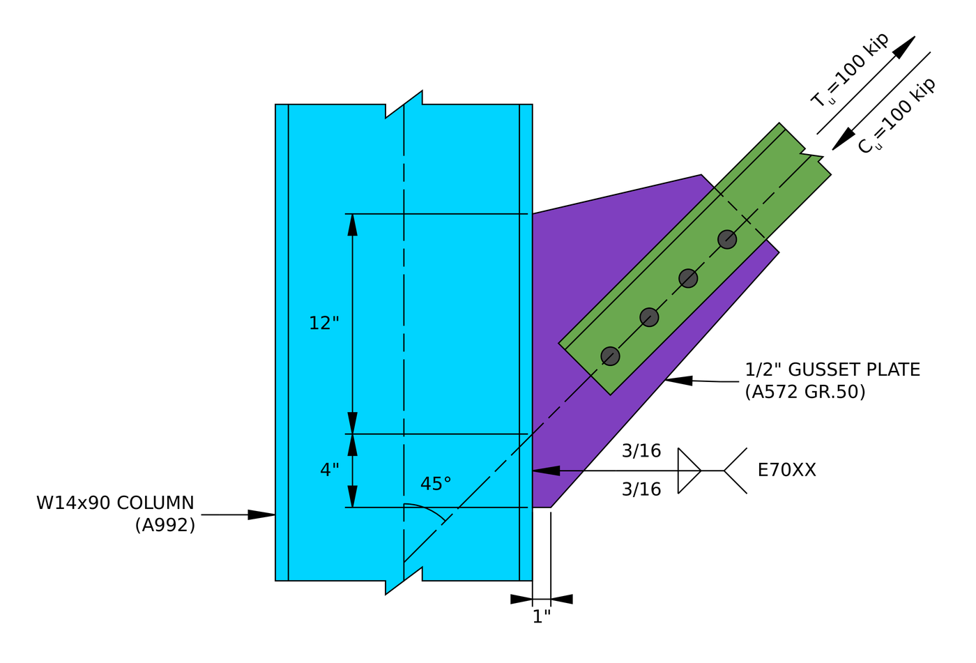
Elevación de la conexión de ejemplo.. The gusset weld runs 12 in above and 4 in below the point where the brace line crosses the column face.
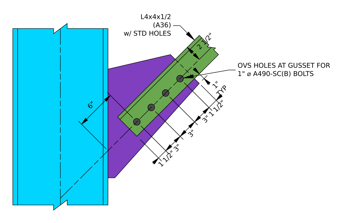
The brace connection. Four bolts at 3 in on a 2 1/2 en calibre, con 1 1/2 in end distances on the angle and on the gusset.
Knee brace connection design: los pasos de un vistazo
- Check the detailing limits at the brace bolts: calibrar, espaciado y distancias al borde.
- Check the slip resistance of the slip-critical bolts.
- Check bolt bearing and tear-out on the gusset plate.
- Check bolt bearing and tear-out on the brace.
- Check block shear of the gusset plate.
- Check block shear of the brace.
- Check the gusset plate in tension on its Whitmore section.
- Check the brace in tension rupture with shear lag.
- Check the gusset plate in compression buckling.
- Check the minimum fillet weld size at the column.
- Resolve the brace force at the column face and check the gusset-to-column weld.
- Check the gusset plate in shear yielding along the column.
- Check the gusset plate in tension yielding along the column.
- Check the column web for local crippling and local yielding.
Entradas de diseño para este ejemplo
El código de diseño es AISC. 360-16 LRFD. Las propiedades de la sección son del Manual AISC..
| Artículo | Símbolo | Valor |
|---|---|---|
| Brace tension load | [mathin] T_{u,br} [mathin] | 100 kip |
| Brace compression load | [mathin] C_{u,br} [mathin] | 100 kip |
| Columna | W14x90, A992 | |
| Profundidad de la columna / espesor de la red | [mathin] d_{c},\ t_{w,c} [mathin] | 14 in / 0.44 in |
| Ancho del ala de la columna / grosor | [mathin] b_{f,c},\ t_{f,c} [mathin] | 14.5 in / 0.71 in |
| Área de columna / kdes | [mathin] A_{c},\ k_{des,c} [mathin] | 26.5 pulgadas² / 1.31 in |
| Rendimiento de la columna / tensión de tracción | [mathin] F_{y,c},\ F_{u,c} [mathin] | 50 KSI / 65 KSI |
| Abrazadera | L4x4x1/2, A36 | |
| Brace area | [mathin] A_{br} [mathin] | 3.75 pulgadas² |
| Brace leg on / off gusset | [mathin] L_{on,gp,br},\ L_{off,gp,br} [mathin] | 4 in / 4 in |
| Brace thickness / centroide | [mathin] t_{br},\ \bar{y} [mathin] | 0.5 in / 1.18 in |
| Brace slope from support | [mathin] \theta_{br} [mathin] | 45° |
| Brace unbraced length (gusset buckling length) | [mathin] L_{b,br} [mathin] | 6 in |
| Brace yield / tensión de tracción | [mathin] F_{y,br},\ F_{u,br} [mathin] | 36 KSI / 58 KSI |
| Módulo de elasticidad | [mathin] E [mathin] | 29000 KSI |
| Artículo | Símbolo | Valor |
|---|---|---|
| Cartela | 1/2 in, A572 Grade 50 | |
| Gusset thickness | [mathin] t_{gp} [mathin] | 0.5 in |
| Gusset yield / tensión de tracción | [mathin] F_{y,gp},\ F_{u,gp} [mathin] | 50 KSI / 65 KSI |
| Pernos | 1 en A490-SC, Class B surface | |
| Diámetro del perno | [mathin] d_{b} [mathin] | 1 in |
| Holes in brace / gusset | Estándar (ETS) / de gran tamaño (OVS) | |
| Bolt gage on the brace leg | [mathin] g_{a} [mathin] | 2.5 in |
| Filas de pernos / espaciado entre filas | [mathin] n_{r},\ s_{r} [mathin] | 4 / 3 in |
| Columnas de pernos | [mathin] n_{c} [mathin] | 1 |
| End distance on brace and gusset | [mathin] L_{ev} [mathin] | 1.5 in |
| Weld at the column | 3/16 en filete, both sides of the gusset, E70XX | |
| Tamaño de soldadura / fuerza de relleno | [mathin] W,\ F_{EXX} [mathin] | 0.1875 in / 70 KSI |
| Weld length above / below the brace line | [mathin] L_{w1},\ L_{w2} [mathin] | 12 in / 4 in |
| Total gusset length along the column | [mathin] L_{WT} [mathin] | 16 in |
The brace length on the gusset adds up from the drawing: dos 1.5 in end distances plus three 3 in spaces, 12 in. The horizontal edge distance on the angle is the leg less the gage, 4 - 2.5 = 1.5 in.
Paso 1: Detailing limits at the brace bolts (AISC 360-16 J3.3, J3.4, J3.5)
The bolt layout has to be buildable and match the assumptions behind the strength equations. Los pernos que están demasiado cerca se rompen entre los agujeros., Los bordes que están demasiado cerca se arrancan., and the gage has to leave room to fit and tighten the bolts next to the angle’s outstanding leg.
Para 1 en perno el espacio mínimo es [mathin] 2\tfrac{2}{3} d_{b} = 2.667\,in [mathin] (J3.3) y la distancia mínima al borde es 1.25 in (Tabla J3.4). The angle has standard holes, asi que 1.25 in applies to it directly. The gusset has oversized holes, por lo que el incremento de la Tabla J3.5 de 1/8 in raises its minimum end distance to 1.375 in.
| Límite de detalles | Límite (in) | Actual (in) | DCR | Resultado |
|---|---|---|---|---|
| Calibre mínimo de pernos | 1.875 | 2.500 | 0.750 | PASAR |
| Distancia mínima entre filas de tornillos | 2.667 | 3.000 | 0.889 | PASAR |
| Distancia máxima entre filas de tornillos | 6.000 | 3.000 | 0.500 | PASAR |
| Gusset plate minimum vertical edge distance | 1.375 | 1.500 | 0.917 | PASAR |
| Brace minimum vertical edge distance | 1.250 | 1.500 | 0.833 | PASAR |
| Brace minimum horizontal edge distance | 1.250 | 1.500 | 0.833 | PASAR |
Para un límite mínimo, la relación es límite sobre real, y para un máximo es un límite real por encima. The governing row is the gusset end distance with its oversized hole increment:
[math] DCR = \frac{d}{c} = \frac{(1.375)}{(1.5)} = 0.91667 [math]
DCR = 0.917 < 1.0, OK
Paso 2: Slip resistance of the bolts (AISC 360-16 J3.8)
The gusset has oversized holes, y AISC 360-16 J3.2 allows oversized holes only in slip-critical joints. So the bolts are pretensioned and the brace force is carried by friction between the angle and the gusset. The check is that the joint does not slip under the factored load.
Dónde [mathin] \phi = 0.85 [mathin] para agujeros de gran tamaño, [mathin] \mu = 0.5 [mathin] for a Class B surface, [mathin] D_{u} = 1.13 [mathin], [mathin] h_{f} = 1 [mathin] porque no hay rellenos, [mathin] T_{b} = 64\,kip [mathin] para 1 en perno A490 (Tabla J3.1), [mathin] N_{s} = 1 [mathin] avión de deslizamiento, [mathin] n_{r} = 4 [mathin] y [mathin] n_{c} = 1 [mathin]:
[math] \phi R_{n} = \phi\, \mu\, D_{u}\, h_{f}\, T_{b}\, N_{s}\, n_{r}\, n_{c} [math]
[math] \phi R_{n} = (0.85) \times (0.5) \times (1.13) \times (1) \times (64\,kip) \times (1) \times (4) \times (1) [math]
[math] \phi R_{n} = 122.94\,kip [math]
DCR = 100 kip / 122.94 salto = 0.813 < 1.0, OK
The same check covers tension and compression, because the brace force is 100 dormir de cualquier manera.
Paso 3: Bolt bearing and tear-out on the gusset plate (AISC 360-16 J3.10)
Slip-critical bolts still have to be checked for bearing, because if the joint does slip the bolts end up bearing on the sides of their holes. In tension the brace pulls the bolts away from the column, so they bear on the gusset toward its outer end. The bolt nearest that end has the least material in front of it.
The gusset hole is oversized, [mathin] d_{h} = 1.25\,in [mathin]. Clear distance for the end bolt, con [mathin] L_{ev} = 1.5\,in [mathin]:
[math] l_{c1} = L_{ev} – \frac{d_{h}}{2} = (1.5\,in) – \frac{(1.25\,in)}{2} = 0.875\,in [math]
Clear distance between bolts, con [mathin] s_{r} = 3\,in [mathin]:
[math] l_{c2} = s_{r} – d_{h} = (3\,in) – (1.25\,in) = 1.75\,in [math]
Dónde [mathin] t_{gp} = 0.5\,in [mathin], [mathin] F_{u,gp} = 65\,ksi [mathin], [mathin] n_{r} = 4 [mathin], [mathin] n_{c} = 1 [mathin], [mathin] d_{b} = 1\,in [mathin] y [mathin] \phi = 0.75 [mathin]:
[math] \phi R_{n,tearout} = \phi \left[ \min\left(1.2\, l_{c1},\, 2.4\, d_{b}\right) t_{gp} F_{u,gp}\, n_{c} + \min\left(1.2\, l_{c2},\, 2.4\, d_{b}\right) t_{gp} F_{u,gp}\, n_{c} \left( n_{r} – 1 \right) \right] [math]
[math] \phi R_{n,tearout} = (0.75) \times \left[ \min\left(1.2 \times (0.875\,in),\, 2.4 \times (1\,in)\right) \times (0.5\,in) \times (65\,ksi) \times (1) + \min\left(1.2 \times (1.75\,in),\, 2.4 \times (1\,in)\right) \times (0.5\,in) \times (65\,ksi) \times (1) \times ((4) – 1) \right] [math]
[math] \phi R_{n,tearout} = 179.16\,kip [math]
DCR = 100 kip / 179.16 salto = 0.558 < 1.0, OK
Tear-out governs every bolt here, because the large oversized hole eats into the clear distance: 1.2 lc is below 2.4 db for both the end bolt and the inner bolts. In compression the bolts bear toward the column instead, where there is far more gusset, so tension is the case that matters.
Paso 4: Bolt bearing and tear-out on the brace (AISC 360-16 J3.10)
The same check applies to the angle leg. In tension the angle is pulled away from the column, so its bolts bear toward the end of the angle nearest the column.
The angle has standard holes, [mathin] d_{h} = 1.125\,in [mathin]:
[math] l_{c1} = L_{ev} – \frac{d_{h}}{2} = (1.5\,in) – \frac{(1.125\,in)}{2} = 0.9375\,in [math]
[math] l_{c2} = s_{r} – d_{h} = (3\,in) – (1.125\,in) = 1.875\,in [math]
Dónde [mathin] t_{br} = 0.5\,in [mathin] y [mathin] F_{u,br} = 58\,ksi [mathin]:
[math] \phi R_{n,tearout} = \phi \left[ \min\left(1.2\, l_{c1},\, 2.4\, d_{b}\right) t_{br} F_{u,br}\, n_{c} + \min\left(1.2\, l_{c2},\, 2.4\, d_{b}\right) t_{br} F_{u,br}\, n_{c} \left( n_{r} – 1 \right) \right] [math]
[math] \phi R_{n,tearout} = (0.75) \times \left[ \min\left(1.2 \times (0.9375\,in),\, 2.4 \times (1\,in)\right) \times (0.5\,in) \times (58\,ksi) \times (1) + \min\left(1.2 \times (1.875\,in),\, 2.4 \times (1\,in)\right) \times (0.5\,in) \times (58\,ksi) \times (1) \times ((4) – 1) \right] [math]
[math] \phi R_{n,tearout} = 171.28\,kip [math]
DCR = 100 kip / 171.28 salto = 0.584 < 1.0, OK
The angle has the smaller hole but the weaker steel. A36 at 58 ksi against the gusset’s 65 ksi more than cancels the extra clear distance, so the brace ends up slightly weaker in bearing.
Paso 5: Block shear of the gusset plate (AISC 360-16 J4.3)
A block of the gusset can tear out along the bolt line: shear along the line of bolts to the gusset’s end, plus tension across from the bolt line to the gusset’s side edge. With one line of bolts, the block is L-shaped.
Área neta en tensión, con [mathin] n_{c} = 1 [mathin], [mathin] s_{c} = 0\,in [mathin] and the gusset edge distance from the bolt line [mathin] L_{eh,gp} = 1.5\,in [mathin]. Cada agujero suma 1/16 en busca de daños durante el punzonado (B4.3):
[math] A_{nt} = t_{gp} \left[ (n_{c}-1)\, s_{c} + L_{eh,gp} – (n_{c} – 0.5) \left( d_{h} + 0.0625\,in \right) \right] [math]
[math] A_{nt} = (0.5\,in) \times \left[ ((1)-1) \times (0\,in) + (1.5\,in) – ((1) – 0.5) \times ((1.25\,in) + (0.0625\,in)) \right] = 0.42188\,in^{2} [math]
Gross area in shear, from the gusset’s end to the farthest bolt:
[math] A_{gv} = t_{gp} \left[ L_{ev} + (n_{r}-1)\, s_{r} \right] = (0.5\,in) \times \left[ (1.5\,in) + ((4)-1) \times (3\,in) \right] = 5.25\,in^{2} [math]
Net area in shear. The report writes the shear length as the 12 in brace length on the gusset, [mathin] L_{br,gp} [mathin], less one end distance, which is the same 10.5 in as in the gross area:
[math] A_{nv} = t_{gp} \left[ L_{br,gp} – L_{ev} – (n_{r} – 0.5)\left( d_{h} + 0.0625\,in \right) \right] [math]
[math] A_{nv} = (0.5\,in) \times \left[ (12\,in) – (1.5\,in) – ((4) – 0.5) \times ((1.25\,in) + (0.0625\,in)) \right] = 2.9531\,in^{2} [math]
Resistencia al corte del bloque, con [mathin] U_{bs} = 1 [mathin] because the tension stress is uniform, [mathin] F_{u,gp} = 65\,ksi [mathin], [mathin] F_{y,gp} = 50\,ksi [mathin] y [mathin] \phi = 0.75 [mathin]:
[math] \phi R_{n} = \phi \left( 0.6\, F_{u,gp} A_{nv} + U_{bs} F_{u,gp} A_{nt} \le 0.6\, F_{y,gp} A_{gv} + U_{bs} F_{u,gp} A_{nt} \right) [math]
[math] \phi R_{n} = (0.75) \times \left( 0.6 \times (65\,ksi) \times (2.9531\,in^{2}) + (1) \times (65\,ksi) \times (0.42188\,in^{2}) \le 0.6 \times (50\,ksi) \times (5.25\,in^{2}) + (1) \times (65\,ksi) \times (0.42188\,in^{2}) \right) [math]
[math] \phi R_{n} = 106.95\,kip [math]
DCR = 100 kip / 106.95 salto = 0.935 < 1.0, OK
Shear rupture on the net section governs. El 1 1/4 in oversized holes take 4.59 in out of the 10.5 in shear length, which is why this check runs so close.
Paso 6: Block shear of the brace (AISC 360-16 J4.3)
The angle leg can tear out the same way: shear along the bolt line to the end of the angle, plus tension from the bolt line to the toe of the leg.
The horizontal edge distance on the angle is [mathin] L_{eh,br} = 1.5\,in [mathin] and the hole is [mathin] d_{h} = 1.125\,in [mathin]:
[math] A_{nt} = t_{br} \left[ (n_{c}-1)\, s_{c} + L_{eh,br} – (n_{c} – 0.5) \left( d_{h} + 0.0625\,in \right) \right] [math]
[math] A_{nt} = (0.5\,in) \times \left[ ((1)-1) \times (0\,in) + (1.5\,in) – ((1) – 0.5) \times ((1.125\,in) + (0.0625\,in)) \right] = 0.45313\,in^{2} [math]
[math] A_{gv} = t_{br} \left[ L_{ev} + (n_{r}-1)\, s_{r} \right] = (0.5\,in) \times \left[ (1.5\,in) + ((4)-1) \times (3\,in) \right] = 5.25\,in^{2} [math]
[math] A_{nv} = t_{br} \left[ L_{br,gp} – L_{ev} – (n_{r} – 0.5)\left( d_{h} + 0.0625\,in \right) \right] [math]
[math] A_{nv} = (0.5\,in) \times \left[ (12\,in) – (1.5\,in) – ((4) – 0.5) \times ((1.125\,in) + (0.0625\,in)) \right] = 3.1719\,in^{2} [math]
Con [mathin] F_{u,br} = 58\,ksi [mathin], [mathin] F_{y,br} = 36\,ksi [mathin], [mathin] U_{bs} = 1 [mathin] y [mathin] \phi = 0.75 [mathin]:
[math] \phi R_{n} = \phi \left( 0.6\, F_{u,br} A_{nv} + U_{bs} F_{u,br} A_{nt} \le 0.6\, F_{y,br} A_{gv} + U_{bs} F_{u,br} A_{nt} \right) [math]
[math] \phi R_{n} = (0.75) \times \left( 0.6 \times (58\,ksi) \times (3.1719\,in^{2}) + (1) \times (58\,ksi) \times (0.45313\,in^{2}) \le 0.6 \times (36\,ksi) \times (5.25\,in^{2}) + (1) \times (58\,ksi) \times (0.45313\,in^{2}) \right) [math]
[math] \phi R_{n} = 102.5\,kip [math]
DCR = 100 kip / 102.5 salto = 0.976 < 1.0, OK
Esta es la verificación que rige toda la conexión.. Net shear rupture governs again, though only just: the yield side of the equation is within 3 kip of it.
Paso 7: Gusset plate in tension on the Whitmore section (AISC 360-16 J4.1)
The brace force enters the gusset through the bolts and spreads out as it travels along the plate. The Whitmore section is the effective width that takes that force at the last bolt: lines drawn from the first bolt, spreading out on each side, measured across the last bolt (Parte del manual AISC 9, Fig. 9-1). The gusset must not yield on that width, and it must not rupture on that width less the hole.
Ancho de Whitmore
The bolt group is [mathin] L_{br} = (n_{r}-1)\, s_{r} = 9\,in [mathin] long and has a single bolt line, asi que [mathin] W_{br} = 0\,in [mathin]. In the report, [mathin] W [mathin] in this step is the Whitmore width, not the weld size:
[math] W = 2\, L_{br} \tan(\theta) + W_{br} = 2 \times (9\,in) \times \tan((18.93)) + (0\,in) = 6.1732\,in [math]
The Manual’s spread angle is 30°, which would give 2 × 9 × tan 30° = 10.39 in. But the gusset’s sloping free edge on the toe side of the angle passes only about 3.1 in from the last bolt, so a 30° line would run off the plate. The report cuts the spread back to 18.93°, which puts the edge of the Whitmore section 3.0866 in from the bolt line, at that free edge, and uses the same width on the other side. Only steel that is actually there is counted.
Cediendo la tensión (Eq. J4-1)
Con [mathin] \phi = 0.9 [mathin], [mathin] F_{y,gp} = 50\,ksi [mathin] y [mathin] t_{gp} = 0.5\,in [mathin]:
[math] \phi R_{n,ty} = \phi\, F_{y,gp}\, t_{gp}\, W = (0.9) \times (50\,ksi) \times (0.5\,in) \times (6.1732\,in) = 138.9\,kip [math]
ruptura de tensión (Eq. J4-2)
The net width removes one oversized hole, [mathin] d_{h} = 1.25\,in [mathin], con [mathin] \phi = 0.75 [mathin] y [mathin] F_{u,gp} = 65\,ksi [mathin]:
[math] \phi R_{n,tr} = \phi\, F_{u,gp}\, t_{gp} \left[ W – n_{c}\left( d_{h} + 0.0625\,in \right) \right] [math]
[math] \phi R_{n,tr} = (0.75) \times (65\,ksi) \times (0.5\,in) \times \left[ (6.1732\,in) – (1) \times ((1.25\,in) + (0.0625\,in)) \right] = 118.48\,kip [math]
[math] \phi R_{n} = \min\left( \phi R_{n,ty},\, \phi R_{n,tr} \right) = \min\left( (138.9\,kip),\, (118.48\,kip) \right) = 118.48\,kip [math]
DCR = 100 kip / 118.48 salto = 0.844 < 1.0, OK
Paso 8: Brace in tension rupture with shear lag (AISC 360-16 D3, J4.1)
Only one leg of the angle is bolted, so the force has to flow from the outstanding leg into the bolted leg near the connection. That uneven stress is shear lag, and AISC handles it with the factor U, which reduces the net area.
From Table D3.1, Caso 2, with the angle’s centroid [mathin] \bar{y} = 1.18\,in [mathin] measured from the bolted face and the connection length [mathin] (n_{r} – 1)\, s_{r} = 9\,in [mathin]:
[math] U = 1 – \frac{\bar{y}}{(n_{r} – 1)\, s_{r}} = 1 – \frac{(1.18\,in)}{((4) – 1) \times (3\,in)} = 0.86894 [math]
Dónde [mathin] A_{br} = 3.75\,in^{2} [mathin], [mathin] d_{h} = 1.125\,in [mathin], [mathin] t_{br} = 0.5\,in [mathin], [mathin] F_{u,br} = 58\,ksi [mathin] y [mathin] \phi = 0.75 [mathin]:
[math] \phi R_{n,tr} = \phi\, F_{u,br}\, U \left[ A_{br} – n_{c}\left( d_{h} + 0.0625\,in \right) t_{br} \right] [math]
[math] \phi R_{n,tr} = (0.75) \times (58\,ksi) \times (0.86894) \times \left[ (3.75\,in^{2}) – (1) \times ((1.125\,in) + (0.0625\,in)) \times (0.5\,in) \right] = 119.3\,kip [math]
DCR = 100 kip / 119.3 salto = 0.838 < 1.0, OK
A longer bolt group raises U. With six bolts instead of four, the connection length would be 15 in and U would be 1 - 1.18/15 = 0.92.
Paso 9: Gusset plate in compression buckling (AISC 360-16 J4.4, E3)
When the brace is in compression it pushes the gusset toward the column. The strip of gusset between the last bolt and the column face can buckle out of plane, so it is checked as a column with the Whitmore width as its cross section.
The buckling length is the 6 in shown on the drawing, from the line of the bolt nearest the column to the column face, measured along the brace. The report labels it the brace unbraced length, [mathin] L_{b,br} = 6\,in [mathin]. The gusset is welded to the column on one edge only and its free end can sway out of plane with the brace, so the report takes [mathin] K = 1.2 [mathin]. For a solid rectangle, [mathin] r = t_{gp}/\sqrt{12} = 0.14434\,in [mathin]:
[math] \frac{KL}{r} = \frac{(1.2) \times (6\,in)}{(0.5\,in)/\sqrt{12}} = 49.883 [math]
Ya que [mathin] KL/r \gt 25 [mathin], J4.4 sends the check to Chapter E. Elastic buckling stress:
[math] F_{e} = \frac{\pi^{2} E}{\left( \frac{KL}{r} \right)^{2}} = \frac{\pi^{2} \times (29000\,ksi)}{((49.883))^{2}} = 115.02\,ksi [math]
[math] 4.71 \sqrt{\frac{E}{F_{y}}} = 113.43 [math]
Ya que [mathin] KL/r \le 4.71\sqrt{E/F_{y}} [mathin], the inelastic equation E3-2 applies:
[math] F_{cr} = \left( 0.658^{\frac{F_{y,gp}}{F_{e}}} \right) F_{y,gp} = \left( 0.658^{\frac{(50\,ksi)}{(115.02\,ksi)}} \right) \times (50\,ksi) = 41.683\,ksi [math]
Con [mathin] \phi = 0.9 [mathin] and the Whitmore width [mathin] W = 6.1732\,in [mathin]:
[math] \phi R_{n} = \phi\, F_{cr}\, t_{gp}\, W = (0.9) \times (41.683\,ksi) \times (0.5\,in) \times (6.1732\,in) = 115.79\,kip [math]
DCR = 100 kip / 115.79 salto = 0.864 < 1.0, OK
The Whitmore width drives this check as much as the slenderness. A gusset with more plate below the brace would get a wider section and a higher strength.
Paso 10: Minimum fillet weld size at the column (AISC 360-16 J2.2b)
A fillet weld that is too small for the parts it joins can crack as it cools, because the thicker part draws heat out of it too fast. Table J2.4 sets the minimum by the thinner part joined. Here that is the 1/2 in gusset, which falls in the over 1/4 dentro 1/2 in band, so the minimum is 3/16 in.
| Límite de detalles | Límite (in) | Actual (in) | DCR | Resultado |
|---|---|---|---|---|
| Minimum fillet weld size | 0.188 | 0.188 | 1.000 | PASAR |
[math] DCR = \frac{d}{c} = \frac{(0.188)}{(0.188)} = 1 [math]
DCR = 1.000, OK
una proporción de 1.000 here is not a near miss. It only says the 3/16 in weld is exactly the smallest size allowed, which is a common and sensible choice.
Paso 11: Gusset-to-column weld (AISC 360-16 J2.4, Guía de diseño AISC 29)
The gusset is welded to the column flange with a 3/16 in fillet on each side. The brace force reaches the column face at an angle and off the centre of the weld, so the weld carries a normal force, a shear and a moment together. This step resolves the brace force at the column face, finds the worst load on the weld, and checks the weld against it.
Límite del metal base en el tamaño de la soldadura (Ecuación manual AISC. 9-2)
The gusset has a weld on both faces, so half its thickness backs each weld. Con [mathin] t_{f,c} = 0.71\,in [mathin], [mathin] F_{u,c} = 65\,ksi [mathin], [mathin] t_{gp} = 0.5\,in [mathin] y [mathin] F_{u,gp} = 65\,ksi [mathin]:
[math] D_{max} = \frac{t_{f,c} F_{u,c} \le \frac{t_{gp}}{2} F_{u,gp}}{3.09\,kip/in \times F_{EXX}/F_{E70XX}} = \frac{(0.71\,in) \times (65\,ksi) \le (0.25\,in) \times (65\,ksi)}{(3.09\,kip/in) \times (1)} = 5.2589 [math]
Eso es 5.2589 sixteenths, respecto 0.329 in, so the full 3/16 in weld counts.
Longitud efectiva de soldadura
The gusset runs [mathin] L_{WT} = 16\,in [mathin] along the column. Each of the two weld lines is reduced by 2W for the ends:
[math] L_{w} = 2 \left[ L_{WT} – 2W \right] = 2 \times \left[ (16\,in) – 2 \times (0.1875\,in) \right] = 31.25\,in [math]
Forces at the column face
Split the 100 kip brace force, [mathin] P_{u,br} [mathin], into a component perpendicular to the column face and one along it:
[math] N_{br} = P_{u,br} \sin(\theta_{br}) = (100\,kip) \times \sin((45)) = 70.711\,kip [math]
[math] V_{br} = P_{u,br} \cos(\theta_{br}) = (100\,kip) \times \cos((45)) = 70.711\,kip [math]
The brace line crosses the column face 12 in below the top of the gusset and 4 in above its bottom, so it misses the middle of the 16 in weld by [mathin] (12 – 4)/2 = 4\,in [mathin]. The shear acts along the weld line and makes no moment about it, but the normal force is 4 in off centre:
[math] M_{br} = \frac{N_{br} \left| L_{w1} – L_{w2} \right|}{2} = \frac{(70.711\,kip) \times |(12\,in) – (4\,in)|}{2} = 23.57\,kip{\cdot}ft [math]
Eso es 282.84 pollo en. The moment adds to the normal force at one end of the weld and subtracts at the other. The report turns the moment into an equivalent normal force using the plastic section modulus of the two weld lines, [mathin] L_{w}^{2}/8 [mathin], which gives the peak normal load:
[math] N_{br,T} = \frac{8\, M_{br}}{L_{w}} + N_{br} = \frac{8 \times (23.57\,kip{\cdot}ft)}{(31.25\,in)} + (70.711\,kip) = 143.12\,kip [math]
The moment is converted to kip-in (× 12) inside that fraction. The resultant at the peak and its angle to the weld axis:
[math] R = \sqrt{\left( N_{br,T} \right)^{2} + \left( V_{br} \right)^{2}} = \sqrt{((143.12\,kip))^{2} + ((70.711\,kip))^{2}} = 159.63\,kip [math]
[math] \theta = \tan^{-1}\left| \frac{N_{br,T}}{V_{br}} \right| = \tan^{-1}\left| \frac{(143.12\,kip)}{(70.711\,kip)} \right| = 63.707 [math]
Weld ductility factor
The load on the weld is not even. It peaks at one end and falls almost to nothing at the other. Fillet welds have limited ductility, so AISC Design Guide 29 and AISC Manual Part 13 design a gusset edge weld for the larger of the peak load and 1.25 times the average of the peak and minimum loads. El 1.25 lets the weld redistribute load before it fractures.
At the low-stress end the bending subtracts from the normal force:
[math] N_{br,min} = \left| N_{br} – \frac{8\, M_{br}}{L_{w}} \right| = \left| (70.711\,kip) – \frac{8 \times (23.57\,kip{\cdot}ft)}{(31.25\,in)} \right| = 1.6971\,kip [math]
[math] R_{min} = \sqrt{\left( N_{br,min} \right)^{2} + \left( V_{br} \right)^{2}} = \sqrt{((1.6971\,kip))^{2} + ((70.711\,kip))^{2}} = 70.731\,kip [math]
[math] R_{w} = \max\left( R,\, 1.25\, \frac{R + R_{min}}{2} \right) = \max\left( (159.63\,kip),\, 1.25 \times \frac{(159.63\,kip) + (70.731\,kip)}{2} \right) = 159.63\,kip [math]
The averaged value is 143.98 kip, so the peak governs.
Fuerza de soldadura (Eq. J2-4)
The resultant is at 63.707° to the weld, so the directional factor [mathin] 1 + 0.5 \sin^{1.5}\theta [mathin] adds about 42% to the strength. Con [mathin] \phi = 0.75 [mathin] y [mathin] F_{EXX} = 70\,ksi [mathin]:
[math] \phi R_{n} = \phi\, 0.6\, F_{EXX} \frac{\sqrt{2}}{2} \left( W \le \frac{D_{max}}{16} \right) \left[ 1 + 0.5 \left( \sin\theta \right)^{1.5} \right] L_{w} [math]
[math] \phi R_{n} = (0.75) \times 0.6 \times (70\,ksi) \times \frac{\sqrt{2}}{2} \times \left( (0.1875\,in) \le \frac{(5.2589)}{(16)} \right) \times \left[ 1 + 0.5 \times (\sin(63.707))^{1.5} \right] \times (31.25\,in) [math]
[math] \phi R_{n} = 185.91\,kip [math]
DCR = 159.63 kip / 185.91 salto = 0.859 < 1.0, OK
El 4 in eccentricity costs a lot here. Without it the weld would carry a 100 kip resultant instead of 159.63 kip. Centring the gusset on the point where the brace line crosses the column face removes the moment.
Paso 12: Gusset plate in shear yielding along the column (AISC 360-16 J4.2)
The component of the brace force along the column face, [mathin] V_{br} = 70.711\,kip [mathin], passes through the gusset’s welded edge as shear. The gross section along that edge must not yield.
Con [mathin] L_{WT} = 16\,in [mathin], [mathin] t_{gp} = 0.5\,in [mathin], [mathin] F_{y,gp} = 50\,ksi [mathin] y [mathin] \phi = 1 [mathin]:
[math] A_{gv} = L_{WT}\, t_{gp} = (16\,in) \times (0.5\,in) = 8\,in^{2} [math]
[math] \phi R_{n,sy} = \phi\, 0.6\, F_{y,gp} A_{gv} = (1) \times 0.6 \times (50\,ksi) \times (8\,in^{2}) = 240\,kip [math]
DCR = 70.711 kip / 240 salto = 0.295 < 1.0, OK
Paso 13: Gusset plate in tension yielding along the column (AISC 360-16 J4.1)
The normal component and the moment put the gusset’s welded edge in tension, highest at one end. Following AISC Design Guide 29, Ejemplo 5.3, the report adds the two as normal stresses on the edge and turns the peak back into an equivalent force over the full edge.
The normal stress is [mathin] N/(t\,l) + M/(t\,l^{2}/4) [mathin]. Multiplying by [mathin] t\,l [mathin], con [mathin] l = L_{WT} = 16\,in [mathin]:
[math] N_{e} = \left| N_{br} \right| + \frac{4 \left| M_{br} \right|}{L_{WT}} = |(70.711\,kip)| + \frac{4 \times |(23.57\,kip{\cdot}ft)|}{(16\,in)} = 141.42\,kip [math]
This is slightly below the weld’s 143.12 kip because it uses the 16 in gusset edge rather than the 31.25 in of effective weld split over two lines. Con [mathin] \phi = 0.9 [mathin]:
[math] \phi R_{n,ty} = \phi\, F_{y,gp}\, t_{gp}\, L_{WT} = (0.9) \times (50\,ksi) \times (0.5\,in) \times (16\,in) = 360\,kip [math]
DCR = 141.42 kip / 360 salto = 0.393 < 1.0, OK
Paso 14: Column web local crippling and local yielding (AISC 360-16 J10.3, J10.2)
The gusset delivers a concentrated force to the column flange over its 16 de largo. When the brace is in compression, that force pushes on the flange, and the column web behind it can yield locally or crumple (cripple). The demand is the peak normal load from Step 11, [mathin] N_{br,T} = 143.12\,kip [mathin].
Web local paralizante (Eq. J10-4)
Con [mathin] \phi = 0.75 [mathin], [mathin] t_{w,c} = 0.44\,in [mathin], bearing length [mathin] L_{WT} = 16\,in [mathin], [mathin] d_{c} = 14\,in [mathin], [mathin] t_{f,c} = 0.71\,in [mathin], [mathin] F_{y,c} = 50\,ksi [mathin] y [mathin] Q_{f} = 1 [mathin]:
[math] \phi R_{n,wlc} = \phi\, 0.8 \left( t_{w,c} \right)^{2} \left[ 1 + 3 \left( \frac{L_{WT}}{d_{c}} \right) \left( \frac{t_{w,c}}{t_{f,c}} \right)^{1.5} \right] \sqrt{\frac{E\, F_{y,c}\, t_{f,c}}{t_{w,c}}}\, Q_{f} [math]
[math] \phi R_{n,wlc} = (0.75) \times 0.8 \times ((0.44\,in))^{2} \times \left[ 1 + 3 \times \left( \frac{(16\,in)}{(14\,in)} \right) \times \left( \frac{(0.44\,in)}{(0.71\,in)} \right)^{1.5} \right] \times \sqrt{\frac{(29000\,ksi) \times (50\,ksi) \times (0.71\,in)}{(0.44\,in)}} \times (1) [math]
[math] \phi R_{n,wlc} = 474.88\,kip [math]
Rendimiento local web (Eq. J10-2)
The force spreads through the flange and fillet on a 2.5:1 slope on each side, so the web yields over [mathin] 5k + l_{b} [mathin]. Con [mathin] \phi = 1 [mathin] y [mathin] k_{des,c} = 1.31\,in [mathin]:
[math] \phi R_{n,wly} = \phi\, F_{y,c}\, t_{w,c} \left( 5\, k_{des,c} + L_{WT} \right) = (1) \times (50\,ksi) \times (0.44\,in) \times \left( 5 \times (1.31\,in) + (16\,in) \right) = 496.1\,kip [math]
[math] \phi R_{n} = \min\left( \phi R_{n,wlc},\, \phi R_{n,wly} \right) = \min\left( (474.88\,kip),\, (496.1\,kip) \right) = 474.88\,kip [math]
DCR = 143.12 kip / 474.88 salto = 0.301 < 1.0, OK
A long gusset spreads the force well, so the column web has plenty in reserve and needs no stiffener.
Summary of checks
| Verificación de diseño | Demanda | Capacidad | DCR | Resultado |
|---|---|---|---|---|
| Detailing limits at the brace bolts | 1.375 in | 1.500 in | 0.917 | PASAR |
| Bolts in shear (slip-critical) | 100.000 kip | 122.944 kip | 0.813 | PASAR |
| Bolt bearing on the gusset plate | 100.000 kip | 179.156 kip | 0.558 | PASAR |
| Bolt bearing on the brace | 100.000 kip | 171.281 kip | 0.584 | PASAR |
| Block shear of the gusset plate | 100.000 kip | 106.945 kip | 0.935 | PASAR |
| Block shear of the brace | 100.000 kip | 102.497 kip | 0.976 | PASAR |
| Gusset plate in tension | 100.000 kip | 118.480 kip | 0.844 | PASAR |
| Brace in tension rupture | 100.000 kip | 119.303 kip | 0.838 | PASAR |
| Gusset plate in compression | 100.000 kip | 115.792 kip | 0.864 | PASAR |
| Minimum fillet weld size | 0.188 in | 0.188 in | 1.000 | PASAR |
| Weld at gusset to column | 159.634 kip | 185.906 kip | 0.859 | PASAR |
| Gusset shear yielding along the column | 70.711 kip | 240.000 kip | 0.295 | PASAR |
| Gusset tension yielding along the column | 141.421 kip | 360.000 kip | 0.393 | PASAR |
| Column web (local crippling governs) | 143.118 kip | 474.882 kip | 0.301 | PASAR |
The connection passes every check of this knee brace connection design. Block shear of the brace governs the strength checks at 0.976, with block shear of the gusset next at 0.935. Both come from the same short bolt line with large holes. The minimum weld size shows 1.000 only because the weld is exactly the Table J2.4 minimum. en la columna, the weld is the busiest item at 0.859, mostly because of the 4 in eccentricity.
Qué cambiar si falla un cheque
- Block shear of the brace or gusset: agregar una fila de tornillos, which lengthens the shear planes. A larger end distance or a longer edge distance to the gusset’s side also helps. On the gusset, standard holes instead of oversized holes add net area.
- Resistencia al deslizamiento: add bolts, use un perno más grande, or use standard holes in the gusset, which raises φ from 0.85 a 1.00.
- Bearing and tear-out: increase the end distance or the bolt spacing, or use a thicker gusset.
- Brace tension rupture: lengthen the bolt group to raise U, or use a heavier angle.
- Gusset tension or compression: a thicker gusset raises both. Adding plate on the toe side of the brace widens the Whitmore section, and moving the bolts closer to the column shortens the buckling length.
- Weld at the column: centre the gusset on the point where the brace line meets the column face to remove the moment, make the gusset longer, or use a larger fillet. The base metal allows up to about 5/16 in here.
- Column web: lengthen the gusset to spread the force, or add a pair of stiffeners or a doubler plate.
Preguntas frecuentes
What is a knee brace used for?
A knee brace is a short diagonal between a column and a beam or rafter, set a short distance from their joint. It stiffens the frame corner against sway and gives the members an intermediate brace point. Because it is short and sits close to the joint, it often carries a large axial force for its size, in tension or compression depending on which way the frame sways. That is why this example designs for 100 kip both ways.
Why are the bolts slip-critical?
The gusset has oversized holes, which give the erector tolerance to fit the brace. AISC 360-16 J3.2 permite agujeros de gran tamaño sólo en conexiones de deslizamiento crítico, so the bolts are pretensioned and the faying surfaces are prepared to Class B. A brace that reverses between tension and compression also benefits from a joint that does not slip back and forth. Slip-critical bolts are still checked for bearing and tear-out, as in Steps 3 y 4.
What is the Whitmore section, and why is the spread angle 18.93° here?
The Whitmore section is the effective width of gusset that resists the brace force at the end of the bolt group. You find it by drawing lines at 30° from the first bolt on each side of the bolt line and measuring across them at the last bolt. In this example the gusset’s sloping free edge is closer to the bolts than those 30° lines would reach, so the report limits the spread to 18.93°. The Whitmore width then stays inside the plate, a 6.1732 en lugar de 10.39 in.
Why is K = 1.2 used for gusset buckling?
The gusset is welded to the column along one edge, and the brace end of it is free to move out of plane. That is a column fixed against rotation at both ends but free to translate at one, for which the AISC Commentary gives a recommended K of 1.2. A corner gusset attached to both a beam and a column is held on two edges and is usually given a lower K. Utilizando 1.2 for a knee brace gusset is the conservative choice.
Where does the moment on the gusset-to-column weld come from?
The brace line meets the column face 12 in below the top of the gusset and 4 in above its bottom, so it misses the centre of the 16 in weld by 4 in. The normal component of the brace force, 70.711 kip, interino 4 in off centre gives a moment of 282.84 pollo en, o 23.57 kip-ft. If the gusset were centred on that crossing point there would be no moment, and the weld would only see the 100 kip brace force.
Why is the gusset weld designed for 1.25 times the average load?
The load along a gusset edge weld is uneven, and fillet welds cannot stretch far before they fracture. Guía de diseño AISC 29 designs the weld for the larger of the peak load and 1.25 times the average of the peak and minimum loads, using the weld ductility factor from AISC Manual Part 13. That makes sure the weld can redistribute load along its length. In this example the peak load of 159.63 kip governs over the 143.98 kip average-based value.
Is the Uniform Force Method used for a knee brace gusset?
No. The Uniform Force Method distributes a brace force between the beam and column interfaces of a gusset attached to both, at a beam-column-brace work point. A knee brace gusset is attached to the column flange only. So the brace force is resolved at the column face as a normal force, a shear and a moment, and the gusset edge and its weld are checked for those three together.
¿Cómo cambiaría esto para AISC ASD en lugar de LRFD??
Los estados límite y las resistencias nominales son idénticos.. With AISC ASD you compare the service-level brace force against the nominal strength divided by a safety factor instead of multiplying by a resistance factor. un factor de resistencia de 0.75 se convierte en un factor de seguridad de 2.00, 0.90 se convierte 1.67, and slip with oversized holes goes from 0.85 a 1.76. Las combinaciones de carga también cambian., entonces la demanda es menor.
Design a knee brace connection for free
Cada número en esta página proviene de una solución.. Pick the knee brace configuration, enter your column, abrazadera, gusset, tornillos, weld and brace forces, y mira cada una de estas comprobaciones en tu navegador. No hay nada que instalar.
El módulo SkyCiv Connection Design es el software de diseño de conexiones detrás de este ejemplo.. Le brinda el informe de cálculo completo con cada ecuación y sus números en ella., como los pasos anteriores, más todas las capacidades y DCR, según AISC 360-16 (LRFD y TEA) y AS 4100:2020. El calculadora de pernos y calculadora de soldadura Cubra el grupo de tornillos y verifique las soldaduras por su cuenta..
Referencias
- AISC 360-16, Especificación para edificios de acero estructural: B4.3, D3 (Table D3.1 Case 2), E3 (Eq. E3-1, E3-2, E3-4), J2.2b (Tabla J2.4), J2.4 (Eq. J2-4), J3.2, J3.3, J3.4 (Tabla J3.4), J3.5 (Tabla J3.5), J3.8 (Eq. J3-4, Tabla J3.1), J3.10 (Eq. J3-6a, J3-6c), J4.1 (Eq. J4-1, J4-2), J4.2 (Eq. J4-3), J4.3 (Eq. J4-5), J4.4, J10.2 (Eq. J10-2), J10.3 (Eq. J10-4).
- Manual de construcción en acero AISC, 15a edición: Parte 9, Fig. 9-1 (Whitmore section, página de referencia 9-4) Determine la deflexión y el ángulo de rotación en el extremo B de la viga mostrada en la figura. 9-2; Parte 10, weld length less 2w at the ends; Parte 13, weld ductility factor.
- Guía de diseño AISC 29, Vertical Bracing Connections: gusset edge weld design and Example 5.3.
- Diseño de conexiones de acero utilizando AISC. 360-16
- Pernos y soldaduras en Diseño de conexión SkyCiv

Harold Munalem
Gerente de producto, Diseño de Conexión
10+ años en el diseño de conexiones de acero
LinkedIn
