
Horizontal brace connection design to AISC 360 follows the brace force through three load paths. primero, the brace bolts deliver the force into the gusset. Then the gusset passes it to the two members it connects to, here a girder and a beam, through bolted single angles. Each load path gets its own checks: deslizar, Llevando, block shear and tension at the brace; cizalla de perno, Llevando, corte de bloque, shear and flexure at each single angle; and bending and buckling of the gusset itself.
Esta página funciona con un ejemplo real de principio a fin.. A W18x50 beam and a W21x44 girder meet at a W14x90 column, y un 1/2 in gusset at the corner between them takes a 2L5x3-1/2×1/2 brace at 45°. The brace carries 52 kip in tension or compression (LRFD). The gusset is bolted to the web of each member through an L4x3x3/8 single angle. El diseño es para AISC. 360-16 y el Manual AISC 15ª edición. Cada ecuación está escrita con sus números., in the same order as the calc sheet that the SkyCiv Connection Design El módulo produce para esta conexión..
What is a horizontal brace connection?
A horizontal brace connection joins a diagonal brace in the plane of a floor or roof to the corner where two framing members meet. Horizontal bracing carries lateral load across a diaphragm that cannot do it alone, such as an open roof or a floor with large openings, and takes it to the vertical bracing. Because the brace lies flat in plan, the gusset is horizontal and is usually connected to the webs of the beams just below the top flange.
In this example the gusset sits in the corner between a W18x50 beam and a W21x44 girder at a W14x90 column. It is notched around the column, so it has two legs: one along the girder and one along the beam. Each leg is bolted to its member through a conexión de ángulo único. The brace is a pair of 5×3-1/2×1/2 angles with their short legs back to back. Ambas cosas 5 in legs lie flat on the same face of the gusset, with one line of four bolts through each. The brace-to-gusset checks are close to those in a vertical bracing connection, but there is no Uniform Force Method here. The report resolves the brace force into its two components and sends each one to the member it runs along.
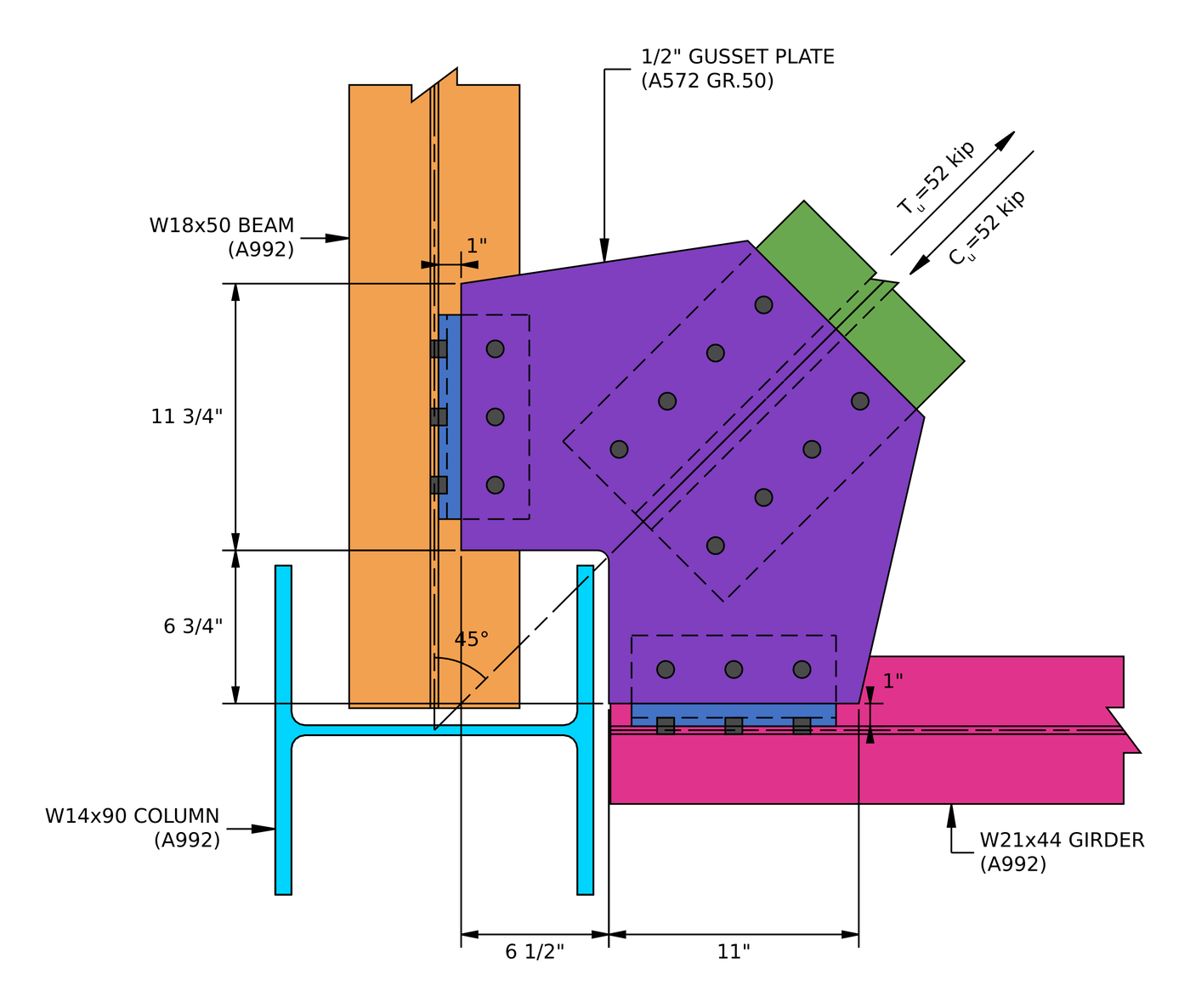
Plan view of the example connection. The gusset leg along the beam is 11 3/4 in long and the leg along the girder is 11 in long.
Horizontal brace connection design: los pasos de un vistazo
- Verifique los límites de detalle en los pernos de refuerzo..
- Check the slip resistance of the brace bolts.
- Check bolt bearing and tear-out on the gusset at the brace.
- Compruebe el cojinete del perno y el desgarro de la abrazadera..
- Check block shear of the gusset at the brace.
- Comprobar el corte del bloque de la riostra.
- Check the gusset in tension on its Whitmore section.
- Compruebe la rotura de la riostra en tensión con retraso de corte.
- Check the detailing limits at the gusset side of the girder angle.
- Check the gusset-side bolt group of the girder angle in shear.
- Check bolt bearing on the girder angle, gusset side.
- Check bolt bearing on the gusset at the girder angle.
- Check the effective strength of the gusset-side bolts.
- Check block shear of the girder angle, gusset side.
- Check block shear of the gusset at the girder angle.
- Check the girder angle in shear.
- Check the gusset in shear along the girder angle.
- Check the girder angle in flexure, gusset side.
- Check shear and moment interaction of the girder angle, gusset side.
- Check the detailing limits at the girder.
- Check the bolt group to the girder by the instantaneous center of rotation.
- Check bolt bearing on the girder angle at the girder.
- Comprobar el apoyo de los pernos en el alma de la viga.
- Check the effective strength of the bolts to the girder.
- Check block shear of the girder angle, girder side.
- Check the girder angle in shear, girder side.
- Check the girder angle in flexure, girder side.
- Check shear and moment interaction of the girder angle, girder side.
- Check the gusset in bending at the girder.
- Check the gusset in buckling at the girder.
- Repeat the bolt and angle checks at the beam.
- Check bolt bearing and block shear of the gusset at the beam angle.
- Check the gusset in shear along the beam angle.
- Check bolt bearing on the beam web.
- Check the gusset in bending at the beam.
- Check the gusset in buckling at the beam.
Entradas de diseño para este ejemplo
El código de diseño es AISC. 360-16 LRFD. Las propiedades de la sección son del Manual AISC..
| Artículo | Símbolo | Valor |
|---|---|---|
| Brace force, tensión o compresión | [mathin] T_{u,br},\ C_{u,br} [mathin] | 52 kip |
| Columna | W14x90, A992 | |
| Profundidad de la columna / espesor de la red | [mathin] d_{c},\ t_{w,c} [mathin] | 14 in / 0.44 in |
| Ancho del ala de la columna / grosor / zona | [mathin] b_{f,c},\ t_{f,c},\ A_{c} [mathin] | 14.5 in / 0.71 in / 26.5 pulgadas² |
| Viga | W21x44, A992 | |
| Profundidad de la viga / espesor de la red | [mathin] d_{g},\ t_{w,g} [mathin] | 20.7 in / 0.35 in |
| Ancho del ala de la viga / grosor / zona | [mathin] b_{f,g},\ t_{f,g},\ A_{g} [mathin] | 6.5 in / 0.45 in / 13 pulgadas² |
| Calculadora de | W18x50, A992 | |
| Profundidad del haz / espesor de la red | [mathin] d_{bm},\ t_{w,bm} [mathin] | 18 in / 0.355 in |
| Ancho del ala de la viga / grosor / zona | [mathin] b_{f,bm},\ t_{f,bm},\ A_{bm} [mathin] | 7.5 in / 0.57 in / 14.7 pulgadas² |
| Beam clearance | [mathin] clr [mathin] | 0 in |
| Columna, girder and beam yield / tensión de tracción | [mathin] F_{y},\ F_{u} [mathin] | 50 KSI / 65 KSI |
| Abrazadera | 2L5x3-1/2×1/2-SLBB, A36 | |
| zona de refuerzo (both angles) | [mathin] A_{br} [mathin] | 8 pulgadas² |
| Brace leg on the gusset / leg off the gusset / grosor | [mathin] L_{on},\ L_{off},\ t_{br} [mathin] | 5 in / 3.5 in / 0.5 in |
| Brace slope from the beam | [mathin] \theta_{br} [mathin] | 45° |
| Longitud sin arriostrar | [mathin] L_{b,br} [mathin] | 13 in |
| Rendimiento de refuerzo / tensión de tracción | [mathin] F_{y,br},\ F_{u,br} [mathin] | 36 KSI / 58 KSI |
| Módulo de elasticidad | [mathin] E [mathin] | 29000 KSI |
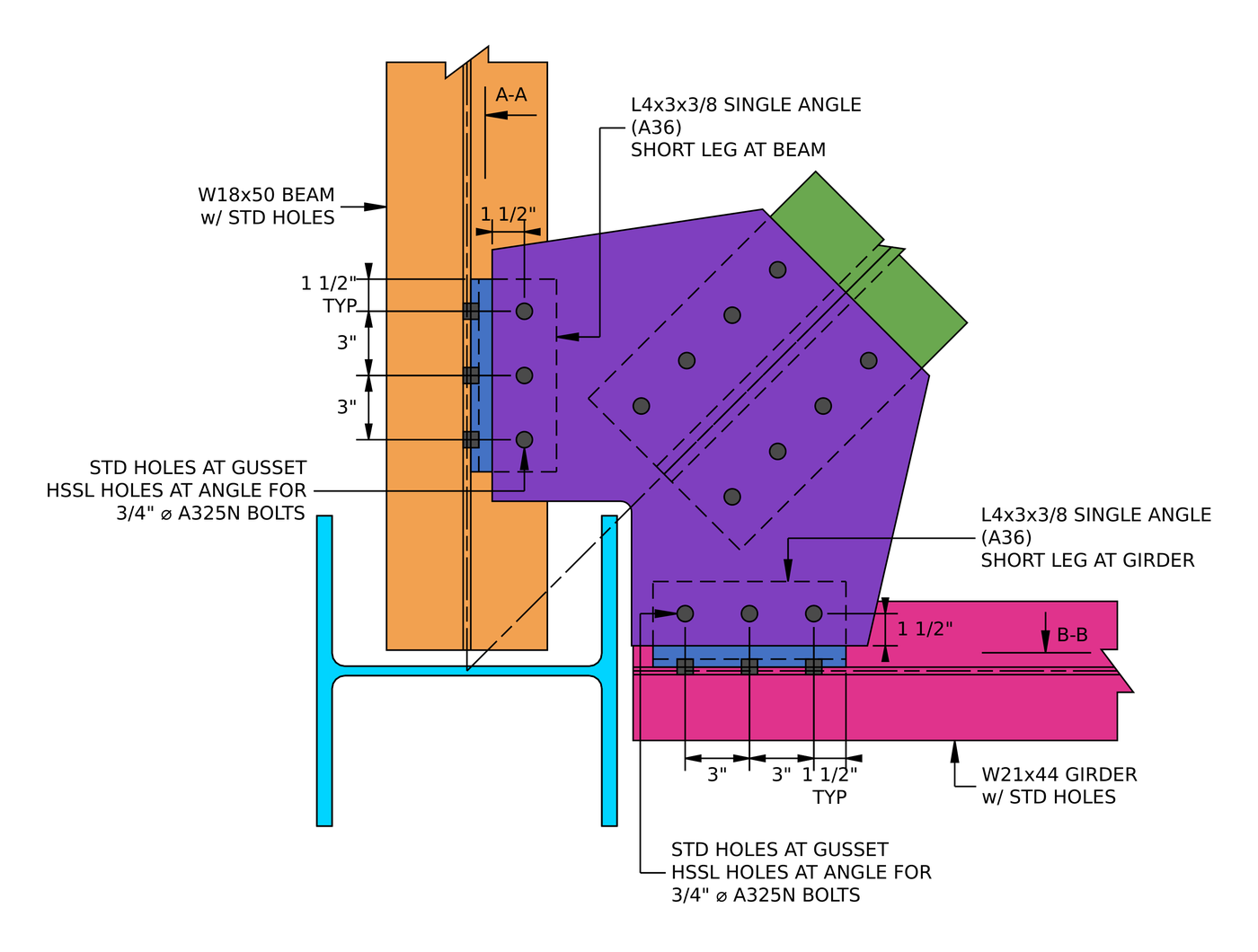
Single angle information. Each angle has its 4 in leg on the gusset and its 3 in leg on the member web, with three bolts at 3 in through each leg.
| Artículo | Símbolo | Valor |
|---|---|---|
| Cartela | 1/2 in, Grado A572 50 | |
| Espesor del refuerzo | [mathin] t_{gp} [mathin] | 0.5 in |
| Rendimiento de refuerzo / tensión de tracción | [mathin] F_{y,gp},\ F_{u,gp} [mathin] | 50 KSI / 65 KSI |
| Brace bolts | 3/4 in A325-SC, Class A surface | |
| Brace bolts: filas / espaciado | [mathin] n_{r},\ s_{r} [mathin] | 4 / 3 in |
| Brace bolts: columnas / gage between the bolt lines | [mathin] n_{c},\ g_{a} [mathin] | 2 / 6 in |
| Brace bolts: end distance at the brace | [mathin] L_{ev} [mathin] | 1.5 in |
| Agujeros en el aparato ortopédico / escudete | Estándar (ETS) / de gran tamaño (OVS) | |
| ángulos individuales (ambos) | L4x3x3/8, A36, 9 in long | |
| Angle leg on the gusset | [mathin] L_{on,g} [mathin] | 4 in |
| Gusset width / longitud / offset at the girder | [mathin] b_{1},\ h_{1},\ o_{1} [mathin] | 6.75 in / 11 in / 1 in |
| Gusset width / longitud / offset at the beam | [mathin] b_{2},\ h_{2},\ o_{2} [mathin] | 6.5 in / 11.75 in / 1 in |
| Angle bolts | 3/4 in A325N | |
| Angle bolts: filas / espaciado / columnas | [mathin] n_{r},\ s_{r},\ n_{c} [mathin] | 3 / 3 in / 1 |
| Gusset side: horizontal edge on the gusset / end distance on the angle | [mathin] L_{eh,gp},\ L_{ev} [mathin] | 1.5 in / 1.5 in |
| Gusset side: holes in the gusset / ángulo | ETS / horizontal short slots (HSSL) | |
| Member side: angle gage / end distance | [mathin] g_{a,to,sup},\ L_{ev} [mathin] | 1.75 in / 1.5 in |
| Member side: holes in the member web / ángulo | ETS / ETS |
The A36 grade on the brace angles and the single angles is normal for those parts. The gusset has oversized holes at the brace, so those bolts must be slip critical (AISC 360-16 J3.2). The single angles have short slots on the gusset leg, perpendicular to the load, which J3.2 allows in a bearing-type joint, so the angle bolts are A325N.
Paso 1: Detallando límites en los pernos de riostra (AISC 360-16 J3.3, J3.4, J3.5)
The bolt layout has to be buildable and has to match the assumptions behind the strength equations. Bolts that are too close tear out between the holes, and bolts too close to an edge tear out to the edge.
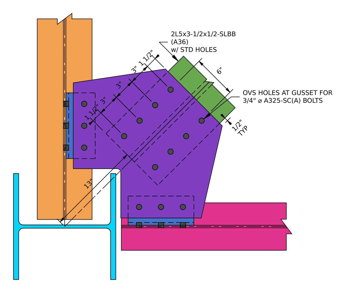
Detalle de conexión de tirantes. Two lines of four bolts at 3 in, one line through each angle, con un 6 in gage between them.
Para 3/4 en perno el espacio mínimo es [mathin] 2\tfrac{2}{3} d_{b} = 2\,in [mathin] (J3.3) y la distancia mínima al borde es 1 in (Tabla J3.4). El refuerzo tiene agujeros de gran tamaño., por lo que el incremento de la Tabla J3.5 de 1/16 in aumenta su distancia final mínima a 1.063 in.
| Límite de detalles | Límite (in) | Actual (in) | DCR | Resultado |
|---|---|---|---|---|
| Calibre mínimo de pernos | 3.375 | 6.000 | 0.563 | PASAR |
| Distancia mínima entre filas de tornillos | 2.000 | 3.000 | 0.667 | PASAR |
| Distancia máxima entre filas de tornillos | 6.000 | 3.000 | 0.500 | PASAR |
| Separación mínima entre columnas de pernos | 2.000 | 3.000 | 0.667 | PASAR |
| Separación máxima entre columnas de pernos | 6.000 | 3.000 | 0.500 | PASAR |
| Gusset minimum vertical edge distance (OVS) | 1.063 | 1.500 | 0.709 | PASAR |
| Distancia mínima al borde vertical del arriostramiento | 1.000 | 1.500 | 0.667 | PASAR |
| Distancia mínima al borde horizontal del arriostramiento | 1.000 | 2.000 | 0.500 | PASAR |
La fila gobernante es la distancia del extremo del refuerzo con su incremento de orificio sobredimensionado.:
[math] DCR = \frac{d}{c} = \frac{(1.063)}{(1.5)} = 0.70867 [math]
DCR = 0.709 < 1.0, OK
Paso 2: Slip resistance of the brace bolts (AISC 360-16 J3.8)
El refuerzo tiene agujeros de gran tamaño., cual AISC 360-16 J3.2 permite solo en juntas de deslizamiento crítico. The bolts are pretensioned, and friction between the brace angles and the gusset carries the brace force. La comprobación es que la junta no resbale bajo la carga mayorada..
Dónde [mathin] \phi = 0.85 [mathin] para agujeros de gran tamaño, [mathin] \mu = 0.3 [mathin] for a Class A surface, [mathin] D_{u} = 1.13 [mathin], [mathin] h_{f} = 1 [mathin] porque no hay rellenos, [mathin] T_{b} = 28\,kip [mathin] para 3/4 in A325 bolt (Tabla J3.1), [mathin] N_{s} = 1 [mathin], [mathin] n_{r} = 4 [mathin] y [mathin] n_{c} = 2 [mathin]:
[math] \phi R_{n} = \phi\, \mu\, D_{u}\, h_{f}\, T_{b}\, N_{s}\, n_{r}\, n_{c} [math]
[math] \phi R_{n} = (0.85) \times (0.3) \times (1.13) \times (1) \times (28\,kip) \times (1) \times (4) \times (2) [math]
[math] \phi R_{n} = 64.546\,kip [math]
DCR = 52 kip / 64.546 salto = 0.806 < 1.0, OK
There is one slip plane, not two, because both brace angles lie on the same face of the gusset. Each bolt clamps one angle leg to the gusset. That makes slip the governing check at the brace.
Paso 3: Bolt bearing and tear-out on the gusset at the brace (AISC 360-16 J3.10)
Aún es necesario comprobar el rodamiento de los pernos críticos para el deslizamiento., because if the joint does slip, the bolts bear on the sides of their holes. The bolt nearest the end of the gusset has the least material in front of it.
El orificio del refuerzo es de gran tamaño., [mathin] d_{h} = 0.9375\,in [mathin]. Clear distances for the end bolt and between bolts:
[math] l_{c1} = L_{ev} – \frac{d_{h}}{2} = (1.5\,in) – \frac{(0.9375\,in)}{2} = 1.0313\,in [math]
[math] l_{c2} = s_{r} – d_{h} = (3\,in) – (0.9375\,in) = 2.0625\,in [math]
Dónde [mathin] t_{gp} = 0.5\,in [mathin], [mathin] F_{u,gp} = 65\,ksi [mathin], [mathin] n_{r} = 4 [mathin], [mathin] n_{c} = 2 [mathin], [mathin] d_{b} = 0.75\,in [mathin] y [mathin] \phi = 0.75 [mathin]:
[math] \phi R_{n} = \phi \left[ \min\left(1.2\, l_{c1},\, 2.4\, d_{b}\right) t_{gp} F_{u,gp}\, n_{c} + \min\left(1.2\, l_{c2},\, 2.4\, d_{b}\right) t_{gp} F_{u,gp}\, n_{c} \left( n_{r} – 1 \right) \right] [math]
[math] \phi R_{n} = (0.75) \times \left[ \min\left(1.2 \times (1.0313\,in),\, 2.4 \times (0.75\,in)\right) \times (0.5\,in) \times (65\,ksi) \times (2) + \min\left(1.2 \times (2.0625\,in),\, 2.4 \times (0.75\,in)\right) \times (0.5\,in) \times (65\,ksi) \times (2) \times ((4) – 1) \right] [math]
[math] \phi R_{n} = 323.58\,kip [math]
DCR = 52 kip / 323.58 salto = 0.161 < 1.0, OK
Tear-out governs the end bolts. The inner bolts reach the bearing cap of 2.4 db.
Paso 4: Cojinete de perno y desgarro en la abrazadera. (AISC 360-16 J3.10)
The same check applies to the brace angles. Each bolt passes through one angle leg, so the bearing thickness is a single leg, [mathin] t_{br} = 0.5\,in [mathin].
The angles have standard holes, [mathin] d_{h} = 0.8125\,in [mathin]:
[math] l_{c1} = (1.5\,in) – \frac{(0.8125\,in)}{2} = 1.0938\,in \qquad l_{c2} = (3\,in) – (0.8125\,in) = 2.1875\,in [math]
Con [mathin] F_{u,br} = 58\,ksi [mathin]:
[math] \phi R_{n} = \phi \left[ \min\left(1.2\, l_{c1},\, 2.4\, d_{b}\right) t_{br} F_{u,br}\, n_{c} + \min\left(1.2\, l_{c2},\, 2.4\, d_{b}\right) t_{br} F_{u,br}\, n_{c} \left( n_{r} – 1 \right) \right] [math]
[math] \phi R_{n} = (0.75) \times \left[ \min\left(1.2 \times (1.0938\,in),\, 2.4 \times (0.75\,in)\right) \times (0.5\,in) \times (58\,ksi) \times (2) + \min\left(1.2 \times (2.1875\,in),\, 2.4 \times (0.75\,in)\right) \times (0.5\,in) \times (58\,ksi) \times (2) \times ((4) – 1) \right] [math]
[math] \phi R_{n} = 292\,kip [math]
DCR = 52 kip / 292 salto = 0.178 < 1.0, OK
Paso 5: Block shear of the gusset at the brace (AISC 360-16 J4.3)
Un bloque del refuerzo puede romperse alrededor de los pernos.: shear along the bolt lines plus tension across the end. The report checks two shapes. The L pattern tears along one bolt line and across to the gusset edge. The U pattern tears along both bolt lines and across between them.
El 1/16 in added to each hole is the B4.3 allowance for damage when the hole is punched. Con [mathin] d_{h} = 0.9375\,in [mathin], [mathin] s_{c} = 3\,in [mathin], [mathin] g_{a} = 6\,in [mathin], [mathin] L_{eh,gp} = 2\,in [mathin] y [mathin] L_{br,gp} = 12\,in [mathin], the brace length on the gusset. For the L pattern:
[math] A_{nt} = t_{gp} \left[ (n_{c} – 2)\, s_{c} + g_{a} + L_{eh,gp} – (n_{c} – 0.5)\left( d_{h} + 0.0625\,in \right) \right] = (0.5\,in) \times \left[ ((2) – 2) \times (3\,in) + (6\,in) + (2\,in) – ((2) – 0.5) \times ((0.9375\,in) + (0.0625\,in)) \right] = 3.25\,in^{2} [math]
[math] A_{gv} = t_{gp} \left[ L_{ev} + (n_{r} – 1)\, s_{r} \right] = (0.5\,in) \times \left[ (1.5\,in) + ((4) – 1) \times (3\,in) \right] = 5.25\,in^{2} [math]
[math] A_{nv} = t_{gp} \left[ L_{br,gp} – L_{ev} – (n_{r} – 0.5)\left( d_{h} + 0.0625\,in \right) \right] = (0.5\,in) \times \left[ (12\,in) – (1.5\,in) – ((4) – 0.5) \times ((0.9375\,in) + (0.0625\,in)) \right] = 3.5\,in^{2} [math]
[math] \phi R_{n} = \phi \left( 0.6\, F_{u,gp} A_{nv} + U_{bs} F_{u,gp} A_{nt} \right) \le \phi \left( 0.6\, F_{y,gp} A_{gv} + U_{bs} F_{u,gp} A_{nt} \right) [math]
[math] \phi R_{n} = (0.75) \times \left( 0.6 \times (65\,ksi) \times (3.5\,in^{2}) + (1) \times (65\,ksi) \times (3.25\,in^{2}) \le 0.6 \times (50\,ksi) \times (5.25\,in^{2}) + (1) \times (65\,ksi) \times (3.25\,in^{2}) \right) = 260.81\,kip [math]
For the U pattern:
[math] A_{nt} = t_{gp} \left[ (n_{c} – 2)\, s_{c} + g_{a} – (n_{c} – 1)\left( d_{h} + 0.0625\,in \right) \right] = (0.5\,in) \times \left[ ((2) – 2) \times (3\,in) + (6\,in) – ((2) – 1) \times ((0.9375\,in) + (0.0625\,in)) \right] = 2.5\,in^{2} [math]
[math] A_{gv} = 2\, t_{gp} \left[ L_{ev} + (n_{r} – 1)\, s_{r} \right] = 2 \times (0.5\,in) \times \left[ (1.5\,in) + ((4) – 1) \times (3\,in) \right] = 10.5\,in^{2} [math]
[math] A_{nv} = 2\, t_{gp} \left[ (n_{r} – 1)\, s_{r} + L_{ev} – (n_{r} – 0.5)\left( d_{h} + 0.0625\,in \right) \right] = 2 \times (0.5\,in) \times \left[ ((4) – 1) \times (3\,in) + (1.5\,in) – ((4) – 0.5) \times ((0.9375\,in) + (0.0625\,in)) \right] = 7\,in^{2} [math]
[math] \phi R_{n} = (0.75) \times \left( 0.6 \times (65\,ksi) \times (7\,in^{2}) + (1) \times (65\,ksi) \times (2.5\,in^{2}) \le 0.6 \times (50\,ksi) \times (10.5\,in^{2}) + (1) \times (65\,ksi) \times (2.5\,in^{2}) \right) = 326.63\,kip [math]
The governing pattern is the lower one:
[math] \phi R_{n} = \min\left( (260.81\,kip),\, (326.63\,kip) \right) = 260.81\,kip [math]
DCR = 52 kip / 260.81 salto = 0.199 < 1.0, OK
Paso 6: Corte en bloque de la riostra (AISC 360-16 J4.3)
Each brace angle can tear out its own block: shear along its bolt line and tension across to the toe of the leg. Each angle has one bolt line, which is why the equation uses half the bolt columns, [mathin] n_{c}/2 = 1 [mathin], and doubles the thickness to cover both angles.
Con [mathin] d_{h} = 0.8125\,in [mathin] y [mathin] L_{eh,br} = 2\,in [mathin]:
[math] A_{nt} = 2 t_{br} \left[ \left( \frac{n_{c}}{2} – 1 \right) s_{c} + L_{eh,br} – \left( \frac{n_{c}}{2} – 0.5 \right)\left( d_{h} + 0.0625\,in \right) \right] = (1\,in) \times \left[ ((1) – 1) \times (3\,in) + (2\,in) – ((1) – 0.5) \times ((0.8125\,in) + (0.0625\,in)) \right] = 1.5625\,in^{2} [math]
[math] A_{gv} = 2 t_{br} \left[ L_{ev} + (n_{r} – 1)\, s_{r} \right] = (1\,in) \times \left[ (1.5\,in) + ((4) – 1) \times (3\,in) \right] = 10.5\,in^{2} [math]
[math] A_{nv} = 2 t_{br} \left[ L_{br,gp} – L_{ev} – (n_{r} – 0.5)\left( d_{h} + 0.0625\,in \right) \right] = (1\,in) \times \left[ (12\,in) – (1.5\,in) – ((4) – 0.5) \times ((0.8125\,in) + (0.0625\,in)) \right] = 7.4375\,in^{2} [math]
[math] \phi R_{n} = (0.75) \times \left( 0.6 \times (58\,ksi) \times (7.4375\,in^{2}) + (1) \times (58\,ksi) \times (1.5625\,in^{2}) \le 0.6 \times (36\,ksi) \times (10.5\,in^{2}) + (1) \times (58\,ksi) \times (1.5625\,in^{2}) \right) = 238.07\,kip [math]
DCR = 52 kip / 238.07 salto = 0.218 < 1.0, OK
Paso 7: Gusset tension on the Whitmore section (AISC 360-16 J4.1, AISC Manual Fig. 9-1)
The brace force spreads out from the bolts into the gusset at about 30° on each side. The Whitmore section is the width that this spread reaches at the last bolt row, and the gusset must yield and rupture on that width before anything else.
The bolt group length is [mathin] L_{br} = (n_{r} – 1)\, s_{r} = 9\,in [mathin] and the width between the outer bolt lines is [mathin] W_{br} = 6\,in [mathin]:
[math] W = 2\, L_{br} \tan(\theta) + W_{br} = 2 \times (9\,in) \times \tan(30) + (6\,in) = 16.392\,in [math]
Cediendo la tensión, con [mathin] \phi = 0.9 [mathin]:
[math] \phi R_{n,ty} = \phi\, F_{y,gp}\, t_{gp}\, W = (0.9) \times (50\,ksi) \times (0.5\,in) \times (16.392\,in) = 368.83\,kip [math]
Tension rupture through the two holes in the last row, con [mathin] \phi = 0.75 [mathin]:
[math] \phi R_{n,tr} = \phi\, F_{u,gp}\, t_{gp} \left[ W – n_{c}\left( d_{h} + 0.0625\,in \right) \right] = (0.75) \times (65\,ksi) \times (0.5\,in) \times \left[ (16.392\,in) – (2) \times ((0.9375\,in) + (0.0625\,in)) \right] = 350.81\,kip [math]
[math] \phi R_{n} = \min\left( (368.83\,kip),\, (350.81\,kip) \right) = 350.81\,kip [math]
DCR = 52 kip / 350.81 salto = 0.148 < 1.0, OK
Paso 8: Brace tension rupture with shear lag (AISC 360-16 D3, J4.1)
Only one leg of each brace angle is bolted, so the stress has to flow from the outstanding leg into the connected leg. Shear lag reduces the effective net area by the factor U.
Con [mathin] \bar{y} = 1.65\,in [mathin], the brace centroid distance, and the connection length [mathin] (n_{r} – 1)\, s_{r} [mathin] (Cuadro D3.1 Caso 2):
[math] U = 1 – \frac{\bar{y}}{(n_{r} – 1)\, s_{r}} = 1 – \frac{(1.65\,in)}{((4) – 1) \times (3\,in)} = 0.81674 [math]
[math] \phi R_{n,tr} = \phi\, F_{u,br}\, U \left[ A_{br} – n_{c}\left( d_{h} + 0.0625\,in \right) t_{br} \right] = (0.75) \times (58\,ksi) \times (0.81674) \times \left[ (8\,in^{2}) – (2) \times ((0.8125\,in) + (0.0625\,in)) \times (0.5\,in) \right] = 253.14\,kip [math]
DCR = 52 kip / 253.14 salto = 0.205 < 1.0, OK
En el lado del aparato ortopédico, slip governs at 0.806 and every strength check is under 0.22.
Paso 9: Detailing limits at the gusset side of the girder angle (AISC 360-16 J3.3, J3.4, J3.5)
The report resolves the brace force into a component along the girder and a component along the beam. The gusset leg at the girder carries the component along the girder, which loads the single angle in shear along its length:
[math] V = P_{u,br} \sin(\theta_{br}) = (52\,kip) \times \sin((45)) = 36.77\,kip [math]
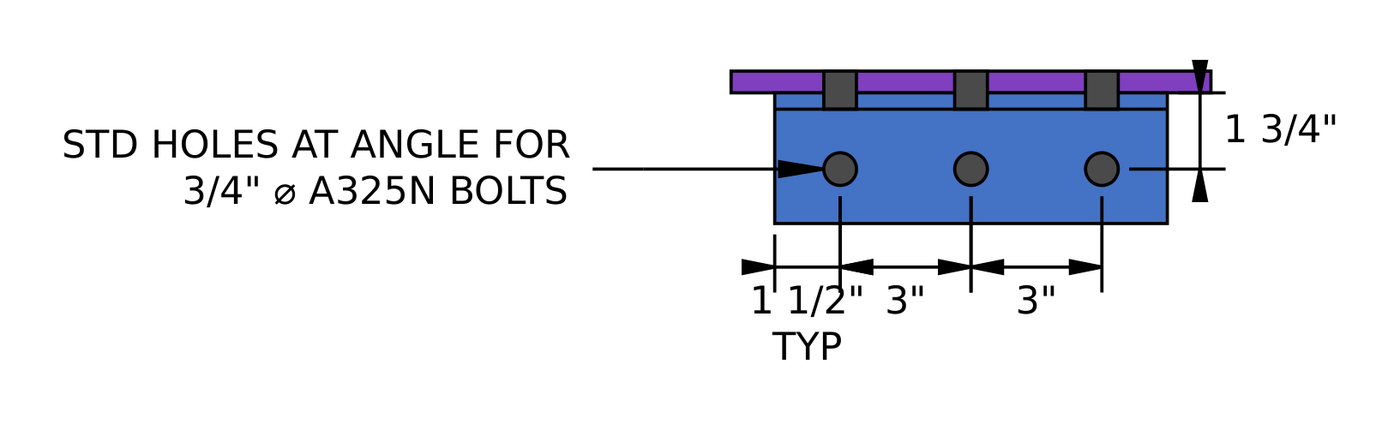
Section B-B at the girder. The angle’s 4 in leg is bolted to the gusset, and its 3 in leg is bolted to the girder web on a 1 3/4 en calibre.
| Límite de detalles | Límite (in) | Actual (in) | DCR | Resultado |
|---|---|---|---|---|
| Distancia mínima entre filas de tornillos | 2.000 | 3.000 | 0.667 | PASAR |
| Distancia máxima entre filas de tornillos | 6.000 | 3.000 | 0.500 | PASAR |
| Single angle minimum vertical edge distance | 1.000 | 1.500 | 0.667 | PASAR |
| Single angle minimum horizontal edge distance (HSSL) | 1.125 | 1.500 | 0.750 | PASAR |
| Gusset minimum vertical edge distance | 1.000 | 2.500 | 0.400 | PASAR |
| Gusset minimum horizontal edge distance | 1.000 | 1.500 | 0.667 | PASAR |
| Minimum single angle length | 5.500 | 9.000 | 0.611 | PASAR |
| Minimum bolt gage for the single angle | 1.500 | 2.500 | 0.600 | PASAR |
The horizontal edge distance on the angle gets the Table J3.5 increment of 1/8 in for a short slot, que da 1.125 in. The minimum angle length of 5.5 in is half the gusset length along the girder, [mathin] h_{1}/2 [mathin].
[math] DCR = \frac{d}{c} = \frac{(1.125)}{(1.5)} = 0.75 [math]
DCR = 0.750 < 1.0, OK
Paso 10: Gusset-side bolt group of the girder angle in shear (AISC 360-16 J3.6, AISC Manual p. 10-116)
The three bolts through the gusset leg of the angle carry V in single shear. For a single vertical row of bolts with an eccentricity of 3 in or less, the Manual lets you neglect the eccentricity, so the group coefficient is the bolt count, [mathin] C = 3 [mathin].
Dónde [mathin] F_{nv} = 54\,ksi [mathin] for an A325N bolt, [mathin] d_{b} = 0.75\,in [mathin], [mathin] N_{s} = 1 [mathin], [mathin] h_{f} = 1 [mathin] y [mathin] \phi = 0.75 [mathin]:
[math] \phi R_{n} = \phi\, F_{nv}\, \frac{\pi}{4} d_{b}^{2}\, N_{s}\, C\, h_{f} = (0.75) \times (54\,ksi) \times \frac{\pi}{4} \times ((0.75\,in))^{2} \times (1) \times (3) \times (1) = 53.677\,kip [math]
DCR = 36.77 kip / 53.677 salto = 0.685 < 1.0, OK
Paso 11: Bolt bearing on the girder angle, gusset side (AISC 360-16 J3.10)
Each bolt bears on its hole in the angle. The angle hole is a horizontal short slot, but the load runs along the angle, across the slot, so the hole dimension in the direction of the load is the slot width, [mathin] d_{h} = 0.8125\,in [mathin].
[math] l_{c1} = (1.5\,in) – \frac{(0.8125\,in)}{2} = 1.0938\,in \qquad l_{c2} = (3\,in) – (0.8125\,in) = 2.1875\,in [math]
Con [mathin] t_{L,gir} = 0.375\,in [mathin], [mathin] F_{u,L,gir} = 58\,ksi [mathin] and the group scaled by [mathin] C/n_{r} [mathin]:
[math] \phi R_{n} = \phi \left[ \min\left(1.2\, l_{c1},\, 2.4\, d_{b}\right) t_{L,gir} F_{u,L,gir} + \min\left(1.2\, l_{c2},\, 2.4\, d_{b}\right) t_{L,gir} F_{u,L,gir} \left( n_{r} – 1 \right) \right] \left( \frac{C}{n_{r}} \right) [math]
[math] \phi R_{n} = (0.75) \times \left[ \min\left(1.2 \times (1.0938\,in),\, 2.4 \times (0.75\,in)\right) \times (0.375\,in) \times (58\,ksi) + \min\left(1.2 \times (2.1875\,in),\, 2.4 \times (0.75\,in)\right) \times (0.375\,in) \times (58\,ksi) \times ((3) – 1) \right] \times \left( \frac{(3)}{(3)} \right) = 80.135\,kip [math]
DCR = 36.77 kip / 80.135 salto = 0.459 < 1.0, OK
Paso 12: Bolt bearing on the gusset at the girder angle (AISC 360-16 J3.10)
The same bolts bear on the gusset, que tiene agujeros estándar. The end bolt has 2.5 in of gusset in front of it, so its clear distance is much longer than on the angle.
[math] l_{c1} = L_{ev,gp} – \frac{d_{h}}{2} = (2.5\,in) – \frac{(0.8125\,in)}{2} = 2.0937\,in \qquad l_{c2} = (3\,in) – (0.8125\,in) = 2.1875\,in [math]
[math] \phi R_{n} = (0.75) \times \left[ \min\left(1.2 \times (2.0937\,in),\, 2.4 \times (0.75\,in)\right) \times (0.5\,in) \times (65\,ksi) + \min\left(1.2 \times (2.1875\,in),\, 2.4 \times (0.75\,in)\right) \times (0.5\,in) \times (65\,ksi) \times ((3) – 1) \right] \times \left( \frac{(3)}{(3)} \right) = 131.63\,kip [math]
DCR = 36.77 kip / 131.63 salto = 0.279 < 1.0, OK
Every bolt reaches the bearing cap of 2.4 db on the gusset, so tear-out does not control here.
Paso 13: Effective strength of the gusset-side bolts (AISC 360-16 J3.6 Comentario)
Corte, bearing and tear-out are not separate checks for each bolt. Each bolt delivers the least of its shear strength and its bearing strength in each ply, y la fuerza del grupo es la suma de esos valores por perno.
[math] \phi r_{v} = \phi\, F_{nv}\, \frac{\pi}{4} d_{b}^{2}\, N_{s}\, h_{f} = (0.75) \times (54\,ksi) \times \frac{\pi}{4} \times ((0.75\,in))^{2} \times (1) \times (1) = 17.892\,kip [math]
On the angle, the edge bolt gives [mathin] \phi r_{n1e} = (0.75) \times \min(1.2 \times 1.0938,\, 2.4 \times 0.75) \times 0.375 \times 58 = 21.41\,kip [mathin] and an inner bolt gives [mathin] \phi r_{n1i} = 29.363\,kip [mathin]. On the gusset, both edge and inner bolts give [mathin] \phi r_{n2} = 43.875\,kip [mathin].
| Tornillo | Cizalla de perno (kip) | Bearing on the angle (kip) | Bearing on the gusset (kip) | Fuerza efectiva (kip) |
|---|---|---|---|---|
| 1 | 17.89 | 29.36 | 43.88 | 17.89 |
| 2 | 17.89 | 29.36 | 43.88 | 17.89 |
| 3 | 17.89 | 21.41 | 43.88 | 17.89 |
[math] \phi R_{n,eff} = \left( \frac{C}{n_{r}} \right) \sum \phi r_{eff} = \left( \frac{(3)}{(3)} \right) \times \left[ (1) \times (17.892\,kip) + (1) \times (17.892\,kip) + (1) \times (17.892\,kip) \right] = 53.677\,kip [math]
DCR = 36.77 kip / 53.677 salto = 0.685 < 1.0, OK
Bolt shear governs every bolt, so the effective strength equals the bolt shear strength from Step 10.
Paso 14: Block shear of the girder angle, gusset side (AISC 360-16 J4.3)
The gusset leg of the angle can tear out an L-shaped block: shear along the bolt line and tension across to the edge of the leg. Al otro lado de la ranura, the hole dimension is the slot length, [mathin] d_{h} = 1\,in [mathin].
[math] A_{nt} = t_{L,gir} \left[ (n_{c} – 1)\, s_{c} + L_{eh} – (n_{c} – 0.5)\left( d_{h} + 0.0625\,in \right) \right] = (0.375\,in) \times \left[ ((1) – 1) \times (0\,in) + (1.5\,in) – ((1) – 0.5) \times ((1\,in) + (0.0625\,in)) \right] = 0.36328\,in^{2} [math]
[math] A_{gv} = t_{L,gir} \left[ L_{ev} + (n_{r} – 1)\, s_{r} \right] = (0.375\,in) \times \left[ (1.5\,in) + ((3) – 1) \times (3\,in) \right] = 2.8125\,in^{2} [math]
[math] A_{nv} = t_{L,gir} \left[ L_{L,gir} – L_{ev} – (n_{r} – 0.5)\left( d_{h} + 0.0625\,in \right) \right] = (0.375\,in) \times \left[ (9\,in) – (1.5\,in) – ((3) – 0.5) \times ((0.8125\,in) + (0.0625\,in)) \right] = 1.9922\,in^{2} [math]
[math] \phi R_{n} = (0.75) \times \left( 0.6 \times (58\,ksi) \times (1.9922\,in^{2}) + (1) \times (58\,ksi) \times (0.36328\,in^{2}) \le 0.6 \times (36\,ksi) \times (2.8125\,in^{2}) + (1) \times (58\,ksi) \times (0.36328\,in^{2}) \right) = 61.365\,kip [math]
DCR = 36.77 kip / 61.365 salto = 0.599 < 1.0, OK
Paso 15: Block shear of the gusset at the girder angle (AISC 360-16 J4.3)
The gusset can tear out the same kind of block around its three bolts. Its end distance is 2.5 in, and the shear plane runs to the end of the 11 in gusset leg.
[math] A_{nt} = t_{gp} \left[ (n_{c} – 1)\, s_{c} + L_{eh,gp} – (n_{c} – 0.5)\left( d_{h} + 0.0625\,in \right) \right] = (0.5\,in) \times \left[ ((1) – 1) \times (0\,in) + (1.5\,in) – ((1) – 0.5) \times ((0.8125\,in) + (0.0625\,in)) \right] = 0.53125\,in^{2} [math]
[math] A_{gv} = t_{gp} \left[ L_{ev,gp} + (n_{r} – 1)\, s_{r} \right] = (0.5\,in) \times \left[ (2.5\,in) + ((3) – 1) \times (3\,in) \right] = 4.25\,in^{2} [math]
[math] A_{nv} = t_{gp} \left[ h_{1} – L_{ev,gp} – (n_{r} – 0.5)\left( d_{h} + 0.0625\,in \right) \right] = (0.5\,in) \times \left[ (11\,in) – (2.5\,in) – ((3) – 0.5) \times ((0.8125\,in) + (0.0625\,in)) \right] = 3.1563\,in^{2} [math]
[math] \phi R_{n} = (0.75) \times \left( 0.6 \times (65\,ksi) \times (3.1563\,in^{2}) + (1) \times (65\,ksi) \times (0.53125\,in^{2}) \le 0.6 \times (50\,ksi) \times (4.25\,in^{2}) + (1) \times (65\,ksi) \times (0.53125\,in^{2}) \right) = 118.22\,kip [math]
DCR = 36.77 kip / 118.22 salto = 0.311 < 1.0, OK
Paso 16: Girder angle in shear (AISC 360-16 J4.2)
The angle leg has to carry V in shear across its full 9 de largo (flexible) y a través de la sección de la red a través de los agujeros (ruptura).
[math] \phi R_{n,sy} = \phi\, 0.6\, F_{y,L,gir}\, A_{gv} = (1) \times 0.6 \times (36\,ksi) \times \left( (9\,in) \times (0.375\,in) \right) = 72.9\,kip [math]
[math] A_{nv} = t_{L,gir} \left[ L_{L,gir} – n_{r}\left( d_{h} + 0.0625\,in \right) \right] = (0.375\,in) \times \left[ (9\,in) – (3) \times ((0.8125\,in) + (0.0625\,in)) \right] = 2.3906\,in^{2} [math]
[math] \phi R_{n,sr} = \phi\, 0.6\, F_{u,L,gir}\, A_{nv} = (0.75) \times 0.6 \times (58\,ksi) \times (2.3906\,in^{2}) = 62.395\,kip [math]
[math] \phi R_{n} = \min\left( (72.9\,kip),\, (62.395\,kip) \right) = 62.395\,kip [math]
DCR = 36.77 kip / 62.395 salto = 0.589 < 1.0, OK
Paso 17: Gusset in shear along the girder angle (AISC 360-16 J4.2)
The gusset leg carries the same force in shear along its 11 de largo.
[math] \phi R_{n,sy} = \phi\, 0.6\, F_{y,gp}\, h_{1}\, t_{gp} = (1) \times 0.6 \times (50\,ksi) \times \left( (11\,in) \times (0.5\,in) \right) = 165\,kip [math]
[math] A_{nv} = t_{gp} \left[ h_{1} – n_{r}\left( d_{h} + 0.0625\,in \right) \right] = (0.5\,in) \times \left[ (11\,in) – (3) \times ((0.8125\,in) + (0.0625\,in)) \right] = 4.1875\,in^{2} [math]
[math] \phi R_{n,sr} = (0.75) \times 0.6 \times (65\,ksi) \times (4.1875\,in^{2}) = 122.48\,kip [math]
DCR = 36.77 kip / 122.48 salto = 0.300 < 1.0, OK
Paso 18: Girder angle in flexure, gusset side (AISC 360-16 F11.2, Parte del manual AISC 9)
The force enters the angle at the gusset bolt line and leaves at the heel, 2.5 in away, so the leg is a short, deep cantilever in bending. Una profunda, thin leg can buckle laterally before it yields. The report checks it with the Manual’s double-coped beam procedure, which treats the leg like a beam web coped top and bottom.
Dónde [mathin] L_{b} = 2.5\,in [mathin], the gage on the gusset leg, [mathin] d = L_{L,gir} = 9\,in [mathin] y [mathin] t = 0.375\,in [mathin]:
[math] \frac{L_{b} d}{t^{2}} = \frac{(2.5\,in) \times (9\,in)}{((0.375\,in))^{2}} = 160, \qquad \frac{0.08 E}{F_{y}} = 64.444 \lt 160 \le \frac{1.9 E}{F_{y}} = 1530.6 [math]
[math] Z = \frac{t\, d^{2}}{4} = \frac{(0.375\,in) \times ((9\,in))^{2}}{4} = 7.5938\,in^{3} \qquad S = \frac{t\, d^{2}}{6} = 5.0625\,in^{3} [math]
[math] C_{b} = \left[ 3 + \ln\left( \frac{L_{b}}{d} \right) \right] \left( 1 – \frac{d_{ct}}{d} \right) \ge 1.84 = \left[ 3 + \ln\left( \frac{(2.5\,in)}{(9\,in)} \right) \right] \times \left( 1 – \frac{(0\,in)}{(9\,in)} \right) \ge 1.84 = 1.84 [math]
[math] \phi M_{n} = \phi \left[ C_{b} \left[ 1.52 – 0.274 \left( \frac{L_{b} d}{t^{2}} \right) \left( \frac{F_{y}}{E} \right) \right] F_{y} S \le F_{y} Z \right] [math]
[math] \phi M_{n} = (0.9) \times \left[ (1.84) \times \left[ 1.52 – 0.274 \times (160) \times \left( \frac{(36\,ksi)}{(29000\,ksi)} \right) \right] \times (36\,ksi) \times (5.0625\,in^{3}) \le (36\,ksi) \times (7.5938\,in^{3}) \right] = 20.503\,kip{\cdot}ft [math]
[math] \phi V_{n,y} = \frac{\phi M_{n}}{L_{b}} = \frac{(20.503\,kip{\cdot}ft)}{(2.5\,in)} = 98.415\,kip [math]
Flexural rupture on the net section through the holes (Parte manual 15 Tabla 15-3, Parte 9 Eq. 9-4):
[math] Z_{net} = \frac{t\, d^{2}}{4} – t\left( d_{h} + 0.0625\,in \right) s_{r} \left\lfloor \frac{n_{r}^{2}}{4} \right\rfloor – \left[ n_{r}\ \text{odd} \right] \frac{t\left( d_{h} + 0.0625\,in \right)^{2}}{4} = 5.5532\,in^{3} [math]
[math] \phi M_{n} = \phi\, F_{u}\, Z_{net} = (0.75) \times (58\,ksi) \times (5.5532\,in^{3}) = 20.13\,kip{\cdot}ft \qquad \phi V_{n,r} = \frac{(20.13\,kip{\cdot}ft)}{(2.5\,in)} = 96.626\,kip [math]
[math] \phi V_{n} = \min\left( (98.415\,kip),\, (96.626\,kip) \right) = 96.626\,kip [math]
DCR = 36.77 kip / 96.626 salto = 0.381 < 1.0, OK
The leg is stocky enough that the plastic moment caps the buckling equation, so yielding and rupture end up close together.
Paso 19: Shear and moment interaction of the girder angle, gusset side (Ecuación manual AISC. 10-5)
The angle section carries shear and moment at the same time, so the two ratios combine in a circular interaction.
[math] M_{r} = V_{r}\, L_{b} = (36.77\,kip) \times (2.5\,in) = 7.6603\,kip{\cdot}ft [math]
[math] I_{nt} = \left( \frac{V_{r}}{\phi V_{n}} \right)^{2} + \left( \frac{M_{r}}{\phi M_{n}} \right)^{2} = \left( \frac{(36.77\,kip)}{(72.9\,kip)} \right)^{2} + \left( \frac{(7.6603\,kip{\cdot}ft)}{(20.503\,kip{\cdot}ft)} \right)^{2} = 0.394 [math]
DCR = 0.394 / 1.0 = 0.394 < 1.0, OK
Paso 20: Detailing limits at the girder (AISC 360-16 J3.3, J3.4)
The angle’s 3 in leg is bolted to the girder web through standard holes in both plies. The same spacing and edge rules apply, plus a minimum gage on the leg so the bolts can be installed.
| Límite de detalles | Límite (in) | Actual (in) | DCR | Resultado |
|---|---|---|---|---|
| Distancia mínima entre filas de tornillos | 2.000 | 3.000 | 0.667 | PASAR |
| Distancia máxima entre filas de tornillos | 6.000 | 3.000 | 0.500 | PASAR |
| Single angle minimum vertical edge distance | 1.000 | 1.500 | 0.667 | PASAR |
| Single angle minimum horizontal edge distance | 1.000 | 1.500 | 0.667 | PASAR |
| Minimum bolt gage for the single angle | 1.500 | 1.750 | 0.857 | PASAR |
[math] DCR = \frac{d}{c} = \frac{(1.5)}{(1.75)} = 0.85714 [math]
DCR = 0.857 < 1.0, OK
Paso 21: Bolt group to the girder by the instantaneous center of rotation (AISC 360-16 J3.6, Parte del manual AISC 7)
The bolts through the girder web sit 1.75 in from the heel of the angle, so V reaches them with an eccentricity of [mathin] e_{x} = 1.75\,in [mathin]. The bolts carry a moment as well as the shear. El metodo instantaneo del centro de rotacion finds the point the group turns about and gives the coefficient C, el número de tornillos’ worth of strength the group actually delivers.
Tornillo 1 is at the origin, and bolts 2 y 3 are at y = 3 en y 6 in. The iteration converges with the instantaneous center at [mathin] x_{ic} = -3.0653\,in [mathin], [mathin] y_{ic} = 3\,in [mathin]. Using Manual Eq. 7-1, the bolt reactions are:
| Tornillo | R (kip) | Rx (kip) | Ry (kip) | Minnesota (pollo en) |
|---|---|---|---|---|
| 1 | 17.56 | 12.28 | 12.55 | 75.32 |
| 2 | 17.01 | 0.00 | 17.01 | 52.14 |
| 3 | 17.56 | -12.28 | 12.55 | 75.32 |
That gives [mathin] C = 2.35 [mathin], contra 3 for the bolts on the gusset leg:
[math] \phi R_{n} = \phi\, F_{nv}\, \frac{\pi}{4} d_{b}^{2}\, N_{s}\, C\, h_{f} = (0.75) \times (54\,ksi) \times \frac{\pi}{4} \times ((0.75\,in))^{2} \times (1) \times (2.35) \times (1) = 42.047\,kip [math]
DCR = 36.77 kip / 42.047 salto = 0.874 < 1.0, OK
El calculadora de pernos runs this same check for any eccentric bolt group on its own.
Paso 22: Bolt bearing on the girder angle at the girder (AISC 360-16 J3.10)
The bolts to the girder bear on the angle’s 3 in leg. Its holes are standard, so the clear distances match Step 11, and the group is scaled by the new C:
[math] \phi R_{n} = (0.75) \times \left[ \min\left(1.2 \times (1.0938\,in),\, 2.4 \times (0.75\,in)\right) \times (0.375\,in) \times (58\,ksi) + \min\left(1.2 \times (2.1875\,in),\, 2.4 \times (0.75\,in)\right) \times (0.375\,in) \times (58\,ksi) \times ((3) – 1) \right] \times \left( \frac{(2.35)}{(3)} \right) = 62.773\,kip [math]
DCR = 36.77 kip / 62.773 salto = 0.586 < 1.0, OK
Paso 23: Apoyo de pernos en el alma de la viga (AISC 360-16 J3.10)
The girder web has no edge near the bolts, so every bolt is an inner bolt, and the check uses [mathin] l_{c2} = 2.1875\,in [mathin] for all of them.
[math] \phi R_{n} = \phi\, \min\left(1.2\, l_{c2},\, 2.4\, d_{b}\right) t_{w,g}\, F_{u,g}\, C = (0.75) \times \min\left(1.2 \times (2.1875\,in),\, 2.4 \times (0.75\,in)\right) \times (0.35\,in) \times (65\,ksi) \times (2.35) = 72.174\,kip [math]
DCR = 36.77 kip / 72.174 salto = 0.509 < 1.0, OK
Paso 24: Effective strength of the bolts to the girder (AISC 360-16 J3.6 Comentario)
As in Step 13, each bolt delivers the least of its shear and its bearing in each ply. On the girder web each bolt gives [mathin] \phi r_{n2} = (0.75) \times \min(1.2 \times 2.1875,\, 2.4 \times 0.75) \times 0.35 \times 65 = 30.713\,kip [mathin].
| Tornillo | Cizalla de perno (kip) | Bearing on the angle (kip) | Bearing on the girder web (kip) | Fuerza efectiva (kip) |
|---|---|---|---|---|
| 1 | 17.89 | 29.36 | 30.71 | 17.89 |
| 2 | 17.89 | 29.36 | 30.71 | 17.89 |
| 3 | 17.89 | 21.41 | 30.71 | 17.89 |
[math] \phi R_{n,eff} = \left( \frac{C}{n_{r}} \right) \sum \phi r_{eff} = \left( \frac{(2.35)}{(3)} \right) \times (53.677\,kip) = 42.047\,kip [math]
DCR = 36.77 kip / 42.047 salto = 0.874 < 1.0, OK
Paso 25: Block shear of the girder angle, girder side (AISC 360-16 J4.3)
The girder leg of the angle can tear out a block the same way as the gusset leg in Step 14. Its holes are standard, so the tension plane uses [mathin] d_{h} = 0.8125\,in [mathin]:
[math] A_{nt} = (0.375\,in) \times \left[ ((1) – 1) \times (0\,in) + (1.5\,in) – ((1) – 0.5) \times ((0.8125\,in) + (0.0625\,in)) \right] = 0.39844\,in^{2} [math]
The shear areas are the same as Step 14, [mathin] A_{gv} = 2.8125\,in^{2} [mathin] y [mathin] A_{nv} = 1.9922\,in^{2} [mathin]:
[math] \phi R_{n} = (0.75) \times \left( 0.6 \times (58\,ksi) \times (1.9922\,in^{2}) + (1) \times (58\,ksi) \times (0.39844\,in^{2}) \le 0.6 \times (36\,ksi) \times (2.8125\,in^{2}) + (1) \times (58\,ksi) \times (0.39844\,in^{2}) \right) = 62.895\,kip [math]
DCR = 36.77 kip / 62.895 salto = 0.585 < 1.0, OK
Paso 26: Girder angle in shear, girder side (AISC 360-16 J4.2)
The girder leg is the same 9 en por 3/8 in section with the same three standard holes, so the numbers repeat Step 16: flexible 72.9 kip, ruptura 62.395 kip.
[math] \phi R_{n} = \min\left( (72.9\,kip),\, (62.395\,kip) \right) = 62.395\,kip [math]
DCR = 36.77 kip / 62.395 salto = 0.589 < 1.0, OK
Paso 27: Girder angle in flexure, girder side (AISC 360-16 F11.2, Parte del manual AISC 9)
On the girder leg the lever arm is the 1.75 en calibre, asi que [mathin] L_{b} = 1.75\,in [mathin] y [mathin] L_{b} d / t^{2} = 112 [mathin]. The plastic moment still caps the buckling equation, asi que [mathin] \phi M_{n} = 20.503\,kip{\cdot}ft [mathin] as in Step 18, and the shorter arm raises the equivalent shear:
[math] \phi V_{n,y} = \frac{(20.503\,kip{\cdot}ft)}{(1.75\,in)} = 140.59\,kip \qquad \phi V_{n,r} = \frac{(20.13\,kip{\cdot}ft)}{(1.75\,in)} = 138.04\,kip [math]
[math] \phi V_{n} = \min\left( (140.59\,kip),\, (138.04\,kip) \right) = 138.04\,kip [math]
DCR = 36.77 kip / 138.04 salto = 0.266 < 1.0, OK
Paso 28: Shear and moment interaction of the girder angle, girder side (Ecuación manual AISC. 10-5)
[math] M_{r} = V_{r}\, L_{b} = (36.77\,kip) \times (1.75\,in) = 5.3622\,kip{\cdot}ft [math]
[math] I_{nt} = \left( \frac{(36.77\,kip)}{(72.9\,kip)} \right)^{2} + \left( \frac{(5.3622\,kip{\cdot}ft)}{(20.503\,kip{\cdot}ft)} \right)^{2} = 0.3228 [math]
DCR = 0.3228 / 1.0 = 0.323 < 1.0, OK
Paso 29: Gusset in bending at the girder (AISC 360-16 F11.1)
The gusset is notched around the column, so it wraps around the corner between its two legs. The force V acts along the girder bolt line, but the gusset section that resists it is offset from that line, so the gusset leg along the girder bends in its own plane.
The lever arm is the gusset offset plus its width at the girder, [mathin] o_{1} + b_{1} [mathin]:
[math] M_{T} = V_{r} \left( o_{1} + b_{1} \right) = (36.77\,kip) \times \left( (1\,in) + (6.75\,in) \right) = 23.747\,kip{\cdot}ft [math]
The section is the 11 in gusset leg, at its plastic moment:
[math] \phi M_{n} = \frac{\phi\, F_{y,gp}\, t_{gp}\, h_{1}^{2}}{4} = \frac{(0.9) \times (50\,ksi) \times (0.5\,in) \times ((11\,in))^{2}}{4} = 56.719\,kip{\cdot}ft [math]
DCR = 23.747 kip-ft / 56.719 kip-ft = 0.419 < 1.0, OK
Paso 30: Gusset in buckling at the girder (AISC 360-16 F11.2)
The same in-plane moment puts one edge of the gusset in compression. A thin plate with a long unsupported edge can buckle sideways before it reaches its plastic moment, so the gusset is checked as a rectangular bar under lateral-torsional buckling.
The report takes the lever arm and the unbraced length out to the middle of the gusset’s other leg, at the beam, [mathin] o_{1} + b_{1} + h_{2}/2 [mathin]:
[math] M_{C} = V_{r} \left( o_{1} + b_{1} + \frac{h_{2}}{2} \right) = (36.77\,kip) \times \left( (1\,in) + (6.75\,in) + \frac{(11.75\,in)}{2} \right) = 41.749\,kip{\cdot}ft [math]
[math] L_{b} = o_{1} + b_{1} + \frac{h_{2}}{2} = (1\,in) + (6.75\,in) + \frac{(11.75\,in)}{2} = 13.625\,in [math]
Section properties of the 11 in leg:
[math] S_{x} = \frac{t_{gp}\, h_{1}^{2}}{6} = 10.083\,in^{3} \qquad Z_{x} = \frac{t_{gp}\, h_{1}^{2}}{4} = 15.125\,in^{3} [math]
[math] M_{y} = F_{y,gp}\, S_{x} = (50\,ksi) \times (10.083\,in^{3}) = 42.014\,kip{\cdot}ft \qquad M_{p} = F_{y,gp}\, Z_{x} = (50\,ksi) \times (15.125\,in^{3}) = 63.021\,kip{\cdot}ft [math]
The slenderness parameter falls between the two limits, so the inelastic equation applies:
[math] \frac{0.08 E}{F_{y}} = 46.4 \lt \frac{L_{b}\, h_{1}}{t_{gp}^{2}} = \frac{(13.625\,in) \times (11\,in)}{((0.5\,in))^{2}} = 599.5 \le \frac{1.9 E}{F_{y}} = 1102 [math]
The report also prints the elastic stress, [mathin] F_{cr} = 1.9 E C_{b} / (L_{b} h_{1} / t_{gp}^{2}) = 91.91\,ksi [mathin], which applies only above the upper limit. Con [mathin] C_{b} = 1 [mathin]:
[math] M_{cr} = \min\left[ C_{b} \left[ 1.52 – 0.274 \left( \frac{L_{b}\, h_{1}}{t_{gp}^{2}} \right) \frac{F_{y,gp}}{E} \right] M_{y},\ M_{p} \right] [math]
[math] M_{cr} = \min\left[ (1) \times \left[ 1.52 – \frac{0.274 \times \left( \frac{(13.625\,in) \times (11\,in)}{((0.5\,in))^{2}} \right) \times (50\,ksi)}{(29000\,ksi)} \right] \times (42.014\,kip{\cdot}ft),\ (63.021\,kip{\cdot}ft) \right] = 51.962\,kip{\cdot}ft [math]
[math] \phi M_{cr} = (0.9) \times (51.962\,kip{\cdot}ft) = 46.766\,kip{\cdot}ft [math]
DCR = 41.749 kip-ft / 46.766 kip-ft = 0.893 < 1.0, OK
This is the highest ratio in the connection. El 1/2 in gusset has a long free edge, so buckling sets its strength at 51.962 kip-ft, well below the plastic moment of 63.021 kip-ft.
Paso 31: Bolt and angle checks at the beam (repeat of Steps 9 a 28)
The gusset leg along the beam carries the other component of the brace force, which at 45° has the same size:
[math] V = P_{u,br} \cos(\theta_{br}) = (52\,kip) \times \cos((45)) = 36.77\,kip [math]
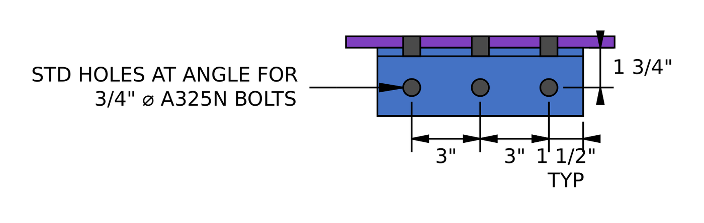
Section A-A at the beam. El ángulo, bolts and gage are the same as at the girder.
El ángulo, tornillos, holes and gages at the beam are the same as at the girder, so every check that depends only on them gives the same result:
| Check at the beam | Same as | Capacidad | DCR |
|---|---|---|---|
| Detallando, gusset side (angle horizontal edge governs) | Paso 9 | 1.5 in | 0.750 |
| Cizalla de perno, gusset side | Paso 10 | 53.677 kip | 0.685 |
| Bearing on the angle, gusset side | Paso 11 | 80.135 kip | 0.459 |
| Fuerza efectiva, gusset side | Paso 13 | 53.677 kip | 0.685 |
| Angle block shear, gusset side | Paso 14 | 61.365 kip | 0.599 |
| Angle shear, gusset side | Paso 16 | 62.395 kip | 0.589 |
| Angle flexure, gusset side | Paso 18 | 96.626 kip | 0.381 |
| Interacción, gusset side | Paso 19 | 1.0 | 0.394 |
| Detailing at the beam | Paso 20 | 1.75 in | 0.857 |
| Bolt group to the beam (ICOR, C = 2.35) | Paso 21 | 42.047 kip | 0.874 |
| Bearing on the angle at the beam | Paso 22 | 62.773 kip | 0.586 |
| Effective strength to the beam | Paso 24 | 42.047 kip | 0.874 |
| Angle block shear, lado de la viga | Paso 25 | 62.895 kip | 0.585 |
| Angle shear, lado de la viga | Paso 26 | 62.395 kip | 0.589 |
| Angle flexure, lado de la viga | Paso 27 | 138.04 kip | 0.266 |
| Interacción, lado de la viga | Paso 28 | 1.0 | 0.323 |
In the gusset-side detailing, two rows change: the gusset end distance is 2.875 in (DCR 0.348), and the minimum angle length becomes [mathin] h_{2}/2 = 5.875\,in [mathin] (DCR 0.653). Neither governs. The checks that involve the gusset dimensions or the beam web follow.
Paso 32: Bolt bearing and block shear of the gusset at the beam angle (AISC 360-16 J3.10, J4.3)
The gusset end distance at the beam is 2.875 in, so the end bolt has more material in front of it than at the girder.
[math] l_{c1} = (2.875\,in) – \frac{(0.8125\,in)}{2} = 2.4687\,in [math]
All three bolts still reach the 2.4 db tapa de cojinete, so the bearing strength is unchanged at 131.63 kip (DCR 0.279). The block shear areas change with the end distance and the 11.75 in leg length:
[math] A_{gv} = (0.5\,in) \times \left[ (2.875\,in) + ((3) – 1) \times (3\,in) \right] = 4.4375\,in^{2} [math]
[math] A_{nv} = t_{gp} \left[ h_{2} – L_{ev,gp} – (n_{r} – 0.5)\left( d_{h} + 0.0625\,in \right) \right] = (0.5\,in) \times \left[ (11.75\,in) – (2.875\,in) – ((3) – 0.5) \times ((0.8125\,in) + (0.0625\,in)) \right] = 3.3438\,in^{2} [math]
Con [mathin] A_{nt} = 0.53125\,in^{2} [mathin] as at the girder:
[math] \phi R_{n} = (0.75) \times \left( 0.6 \times (65\,ksi) \times (3.3438\,in^{2}) + (1) \times (65\,ksi) \times (0.53125\,in^{2}) \le 0.6 \times (50\,ksi) \times (4.4375\,in^{2}) + (1) \times (65\,ksi) \times (0.53125\,in^{2}) \right) = 123.7\,kip [math]
DCR = 36.77 kip / 123.7 salto = 0.297 < 1.0, OK
Paso 33: Gusset in shear along the beam angle (AISC 360-16 J4.2)
The gusset leg along the beam is 11.75 in long, so its shear areas grow with it.
[math] \phi R_{n,sy} = (1) \times 0.6 \times (50\,ksi) \times \left( (11.75\,in) \times (0.5\,in) \right) = 176.25\,kip [math]
[math] A_{nv} = (0.5\,in) \times \left[ (11.75\,in) – (3) \times ((0.8125\,in) + (0.0625\,in)) \right] = 4.5625\,in^{2} \qquad \phi R_{n,sr} = (0.75) \times 0.6 \times (65\,ksi) \times (4.5625\,in^{2}) = 133.45\,kip [math]
DCR = 36.77 kip / 133.45 salto = 0.276 < 1.0, OK
Paso 34: Apoyo de pernos en el alma de la viga (AISC 360-16 J3.10)
The beam web is slightly thicker than the girder web, 0.355 en contra 0.35 in. As in Step 23, every bolt is an inner bolt:
[math] \phi R_{n} = (0.75) \times \min\left(1.2 \times (2.1875\,in),\, 2.4 \times (0.75\,in)\right) \times (0.355\,in) \times (65\,ksi) \times (2.35) = 73.205\,kip [math]
DCR = 36.77 kip / 73.205 salto = 0.502 < 1.0, OK
Per bolt, the beam web gives 31.151 kip. That is still more than the 17.892 kip bolt shear, so the effective strength of the bolts to the beam stays at 42.047 kip (DCR 0.874).
Paso 35: Gusset in bending at the beam (AISC 360-16 F11.1)
This is the same check as Step 29, using the gusset width and leg length at the beam.
[math] M_{T} = V_{r} \left( o_{2} + b_{2} \right) = (36.77\,kip) \times \left( (1\,in) + (6.5\,in) \right) = 22.981\,kip{\cdot}ft [math]
[math] \phi M_{n} = \frac{\phi\, F_{y,gp}\, t_{gp}\, h_{2}^{2}}{4} = \frac{(0.9) \times (50\,ksi) \times (0.5\,in) \times ((11.75\,in))^{2}}{4} = 64.717\,kip{\cdot}ft [math]
DCR = 22.981 kip-ft / 64.717 kip-ft = 0.355 < 1.0, OK
Paso 36: Gusset in buckling at the beam (AISC 360-16 F11.2)
This is the same check as Step 30. The lever arm now runs out to the middle of the girder leg, [mathin] o_{2} + b_{2} + h_{1}/2 [mathin], and the section is the 11.75 in beam leg.
[math] M_{C} = V_{r} \left( o_{2} + b_{2} + \frac{h_{1}}{2} \right) = (36.77\,kip) \times \left( (1\,in) + (6.5\,in) + \frac{(11\,in)}{2} \right) = 39.834\,kip{\cdot}ft \qquad L_{b} = 13\,in [math]
[math] S_{x} = 11.505\,in^{3},\ Z_{x} = 17.258\,in^{3},\ M_{y} = 47.938\,kip{\cdot}ft,\ M_{p} = 71.908\,kip{\cdot}ft [math]
[math] \frac{L_{b}\, h_{2}}{t_{gp}^{2}} = \frac{(13\,in) \times (11.75\,in)}{((0.5\,in))^{2}} = 611 [math]
[math] M_{cr} = \min\left[ (1) \times \left[ 1.52 – \frac{0.274 \times (611) \times (50\,ksi)}{(29000\,ksi)} \right] \times (47.938\,kip{\cdot}ft),\ (71.908\,kip{\cdot}ft) \right] = 59.029\,kip{\cdot}ft [math]
[math] \phi M_{cr} = (0.9) \times (59.029\,kip{\cdot}ft) = 53.126\,kip{\cdot}ft [math]
DCR = 39.834 kip-ft / 53.126 kip-ft = 0.750 < 1.0, OK
The beam leg is longer and deeper than the girder leg, so it buckles at a higher moment, and its ratio is lower than the 0.893 at the girder.
Resumen de controles
| Verificación de diseño | Demanda | Capacidad | DCR | Resultado |
|---|---|---|---|---|
| Brace bolts: detallado | 1.063 in | 1.500 in | 0.709 | PASAR |
| Brace bolts: deslizar | 52 kip | 64.546 kip | 0.806 | PASAR |
| Gusset bearing at the brace | 52 kip | 323.58 kip | 0.161 | PASAR |
| Brace bearing | 52 kip | 291.99 kip | 0.178 | PASAR |
| Gusset block shear at the brace | 52 kip | 260.81 kip | 0.199 | PASAR |
| Brace block shear | 52 kip | 238.07 kip | 0.218 | PASAR |
| Gusset tension (Whitmore) | 52 kip | 350.81 kip | 0.148 | PASAR |
| Ruptura de la tensión del corsé | 52 kip | 253.14 kip | 0.205 | PASAR |
| Girder angle: detallado, gusset side | 1.125 in | 1.500 in | 0.750 | PASAR |
| Girder angle: cizalla de perno, gusset side | 36.77 kip | 53.677 kip | 0.685 | PASAR |
| Girder angle: bearing on the angle, gusset side | 36.77 kip | 80.135 kip | 0.459 | PASAR |
| Girder angle: bearing on the gusset | 36.77 kip | 131.63 kip | 0.279 | PASAR |
| Girder angle: effective strength, gusset side | 36.77 kip | 53.677 kip | 0.685 | PASAR |
| Girder angle: angle block shear, gusset side | 36.77 kip | 61.365 kip | 0.599 | PASAR |
| Girder angle: gusset block shear | 36.77 kip | 118.22 kip | 0.311 | PASAR |
| Girder angle: angle shear, gusset side | 36.77 kip | 62.395 kip | 0.589 | PASAR |
| Girder angle: gusset shear | 36.77 kip | 122.48 kip | 0.300 | PASAR |
| Girder angle: angle flexure, gusset side | 36.77 kip | 96.626 kip | 0.381 | PASAR |
| Girder angle: Interacción, gusset side | 0.394 | 1.000 | 0.394 | PASAR |
| Girder angle: detailing at the girder | 1.500 in | 1.750 in | 0.857 | PASAR |
| Girder angle: bolt group to the girder (ICOR) | 36.77 kip | 42.047 kip | 0.874 | PASAR |
| Girder angle: bearing on the angle at the girder | 36.77 kip | 62.773 kip | 0.586 | PASAR |
| Girder angle: bearing on the girder web | 36.77 kip | 72.174 kip | 0.509 | PASAR |
| Girder angle: effective strength to the girder | 36.77 kip | 42.047 kip | 0.874 | PASAR |
| Girder angle: angle block shear, girder side | 36.77 kip | 62.895 kip | 0.585 | PASAR |
| Girder angle: angle shear, girder side | 36.77 kip | 62.395 kip | 0.589 | PASAR |
| Girder angle: angle flexure, girder side | 36.77 kip | 138.04 kip | 0.266 | PASAR |
| Girder angle: Interacción, girder side | 0.323 | 1.000 | 0.323 | PASAR |
| Gusset bending at the girder | 23.747 kip-ft | 56.719 kip-ft | 0.419 | PASAR |
| Gusset buckling at the girder | 41.749 kip-ft | 46.766 kip-ft | 0.893 | PASAR |
| Beam angle: checks matching the girder angle | 36.77 kip | see Step 31 | 0.874 max | PASAR |
| Beam angle: detallado, gusset side | 1.125 in | 1.500 in | 0.750 | PASAR |
| Beam angle: bearing on the gusset | 36.77 kip | 131.63 kip | 0.279 | PASAR |
| Beam angle: gusset block shear | 36.77 kip | 123.7 kip | 0.297 | PASAR |
| Beam angle: gusset shear | 36.77 kip | 133.45 kip | 0.276 | PASAR |
| Beam angle: apoyo sobre el alma de la viga | 36.77 kip | 73.205 kip | 0.502 | PASAR |
| Gusset bending at the beam | 22.981 kip-ft | 64.717 kip-ft | 0.355 | PASAR |
| Gusset buckling at the beam | 39.834 kip-ft | 53.126 kip-ft | 0.750 | PASAR |
Every check in this horizontal brace connection design passes. Gusset buckling at the girder governs at 0.893: the girder leg of the gusset is the shorter of the two, so it has the smaller section and the longer lever arm to the middle of the other leg. The eccentric bolt groups to the girder and the beam come next at 0.874, followed by slip of the brace bolts at 0.806.
Qué cambiar si falla un cheque
- Gusset buckling or bending: use a thicker gusset, which raises the section and lowers the slenderness parameter at the same time. Lengthening the leg along the member also helps. Reducing the gusset width, and with it the lever arm, works where the brace geometry allows.
- Bolt group to the girder or beam: add a bolt row to the angle, o use un perno más grande. A smaller gage on the member leg reduces the eccentricity but has to stay above the minimum gage.
- Brace bolt slip: use a Class B surface (μ = 0.5 en lugar de 0.3), agregar una fila de tornillos, or use standard holes in the gusset where the erection tolerance allows, which raises φ to 1.00.
- Angle shear, block shear or flexure: use a longer or thicker angle. A longer angle also adds room for another bolt row.
- Bearing on a thin member web: add a bolt row so each bolt carries less, or use a larger bolt diameter.
- Whitmore section or block shear at the brace: lengthen the bolt group to widen the Whitmore section, o usar un refuerzo más grueso.
Preguntas frecuentes
How is the brace force shared between the girder and the beam?
The report resolves the 52 kip brace force into two components at the brace angle of 45 grados. The component along the girder goes to the girder angle, and the component along the beam goes to the beam angle, 36.77 kip each. Each single angle then carries its share as shear along its own bolt line. There is no Uniform Force Method distribution as there is in a vertical brace connection.
Why do the brace bolts have only one slip plane?
Both brace angles lie flat on the same face of the gusset, side by side with a 6 inch gage between their bolt lines. Each bolt passes through one angle leg and the gusset, so there is a single faying surface per bolt. When the gusset sits between two angles, as in many vertical braces, each bolt clamps two surfaces and the slip strength doubles.
Why are the brace bolts slip critical but the angle bolts are not?
The gusset has oversized holes at the brace to give the erector room to fit up the bay. AISC 360-16 J3.2 permite agujeros de gran tamaño sólo en juntas de deslizamiento crítico. The single angles use short slots on the gusset leg, oriented so the load runs across the slot, and J3.2 allows that in a bearing-type joint. Those bolts are A325N, checked for shear and bearing.
Why is the single angle checked like a coped beam?
The force enters the angle at one bolt line and leaves at the other leg, so the leg between them is a short, deep cantilever. A thin, deep plate in bending can buckle laterally. The AISC Manual’s double-coped beam procedure covers a rectangular section like this, so the report uses it, with the bolt gage as the unbraced length and the angle length as the depth.
Why does gusset buckling govern this connection?
The gusset is a half inch plate that wraps around the column, and the force on each leg acts at a long lever arm to the middle of the other leg. That gives a large in-plane moment on a section with a long free edge. Buckling caps the strength below the plastic moment, and the shorter girder leg ends up at a ratio of 0.893.
Why is the bolt group coefficient 3 on the gusset leg but 2.35 on the member leg?
On the gusset leg the bolts are a single row with a small eccentricity, and the AISC Manual lets you neglect an eccentricity of 3 pulgadas o menos, so the coefficient is the bolt count. On the member leg the report takes the 1.75 inch gage as the eccentricity and runs the instantaneous center of rotation method, que da 2.35.
¿Cómo cambiaría esto para AISC ASD en lugar de LRFD??
Los estados límite y las resistencias nominales son los mismos.. With AISC ASD you compare service-level forces against the nominal strength divided by a safety factor. un factor de resistencia de 0.75 se convierte en un factor de seguridad de 2.00, 0.90 se convierte 1.67, y el resbalón con agujeros de gran tamaño va desde 0.85 a 1.76. The split of the brace force between the girder and the beam is unchanged.
Design a horizontal brace connection for free
Cada número en esta página proviene de una solución.. Pick the horizontal bracing configuration, enter your members, abrazadera, escudete, anglos, bolts and forces, and the free calculator runs each of these checks in your browser without anything to install.
El módulo SkyCiv Connection Design es el software de diseño de conexiones detrás de este ejemplo.. Le brinda el informe de cálculo completo con cada ecuación y sus números en ella., como los pasos anteriores, más todas las capacidades y DCR, según AISC 360-16 (LRFD y TEA) y AS 4100:2020.
Referencias
- AISC 360-16, Especificación para edificios de acero estructural: B4.3, D3 (Cuadro D3.1 Caso 2), F11.1, F11.2 (Eq. F11-2), J3.2, J3.3, J3.4 (Tabla J3.4), J3.5 (Tabla J3.5), J3.6 (Eq. J3-1), J3.8 (Eq. J3-4, Tabla J3.1), J3.10 (Eq. J3-6a, J3-6c), J4.1 (Eq. J4-1, J4-2), J4.2 (Eq. J4-3, J4-4), J4.3 (Eq. J4-5).
- Manual de construcción en acero AISC, 15a edición: Parte 7 (centro de rotación instantáneo, Eq. 7-1), Parte 9 (Fig. 9-1 Sección Whitmore, Eq. 9-4, Eq. 9-15), Parte 10 (pag. 10-116 eccentricity of a single row, Eq. 10-5), Parte 15 (Tabla 15-3).
- Diseño de conexiones de acero utilizando AISC. 360-16
- Pernos en Diseño de conexión SkyCiv

Harold Munalem
Gerente de producto, Diseño de Conexión
10+ años en el diseño de conexiones de acero
LinkedIn

