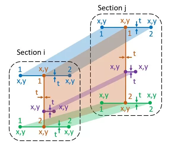
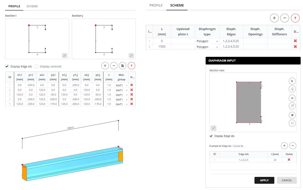
Cada miembro tiene una sección inicial i y una sección final j. Una sección consta de líneas definidas por dos nodos., x,y en el plano de la sección. Cada línea posee un espesor distinto t y pertenece a un grupo de materiales específico.. El punto de referencia para x,Las coordenadas y se pueden elegir arbitrariamente en el espacio para cada sección.. El número de líneas en cada sección debe ser consistente.. Los datos de la tabla se pueden ingresar manualmente o importar desde una hoja de Excel.. Adicionalmente, Las formas de las secciones se pueden importar desde un archivo DXF almacenado en la PC del usuario..
Actualizar t: El grosor común se puede cambiar para un grupo seleccionado de líneas.
Actualizar tapete.: El grupo de materiales común se puede cambiar para el grupo seleccionado de líneas.
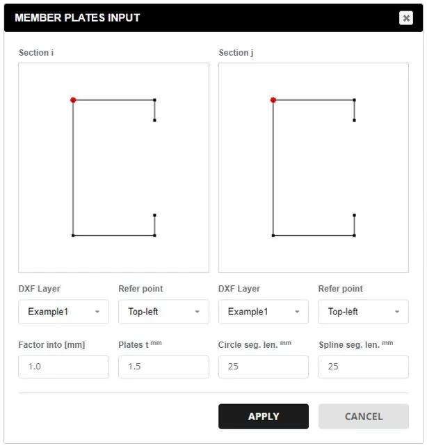
Datos de DXF.: Seleccione un archivo DXF desde su PC. Elija la capa deseada para los elementos de la sección. El punto de referencia determina el origen de la x,y coordenadas. Utilice el factor para escalar las coordenadas de la sección a milímetros. Se aplicará un grosor predeterminado a todas las líneas., que se puede modificar más tarde. Las entidades DXF admitidas incluyen: Líneas, Polilíneas, Arcos, y splines. Para arcos y splines, La división del segmento se especifica para que coincida con el tamaño de malla preferido..
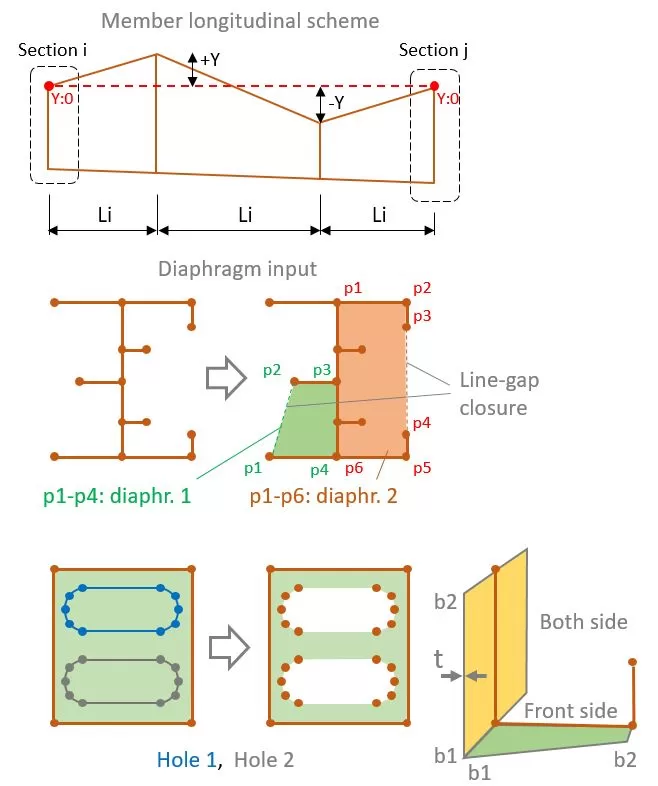
El miembro completo puede representarse mediante una sola longitud L o mediante una serie de segmentos Li.. Independientemente del número de segmentos, las líneas de sección inicial y final tendrán las mismas coordenadas definidas en la pestaña PERFIL. Cada sección también puede tener una posición Y diferente..
Para cada segmento donde L no es igual a 0, el espesor de un grupo de placas se puede actualizar en la "columna t de placa actualizada". Ingresar 0 para ocultar la placa y un valor mayor que 0 para modificar el espesor (t).
Para secciones de segmento, Se puede agregar un diafragma si el 'Polígono’ se elige el tipo. Para especificar uno o más diafragmas, seleccione las líneas que componen la forma. Sólo se permite un cierre de espacio de línea para formar la forma..
También se pueden incorporar agujeros dentro del diafragma.. Para hacer esto, definir las formas de los agujeros seleccionando las líneas correspondientes que abarcan los agujeros.
Si se especifica un diafragma, luego las alas o rigidizadores también se pueden definir seleccionando sus líneas asociadas. Cada ala o refuerzo tiene un ancho inicial y final. (b1,b2), grosor t, y grupo de materiales.
Ejemplo
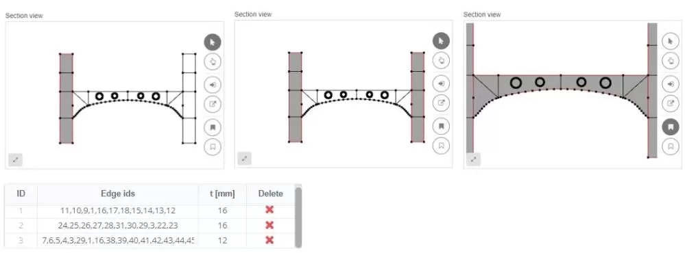
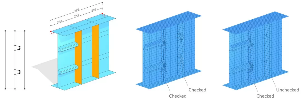
Al disponer los bordes dentro de un diafragma, se pueden incluir en el patrón de mallado. Por ejemplo, Puede surgir una situación en la que un refuerzo longitudinal esté conectado a uno vertical.. En tales escenarios, los 'bordes interiores’ La opción debe estar activada.. sin embargo, si el refuerzo vertical no está unido a nada, esta opción se puede desactivar.