基本板设计示例使用en 1993-1-8:2005, 在 1993-1-1:2005, 在 1992-1-1:2004, 和EN 1992-4:2018.
问题陈述
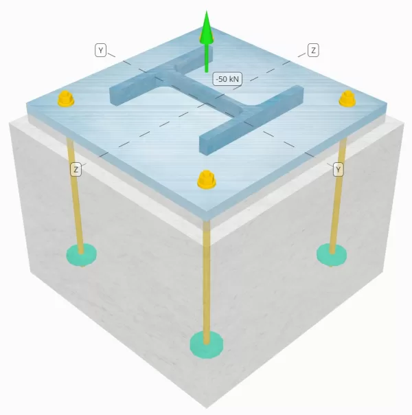
确定设计的列板连接是否足以满足50k的张力负载.
给定数据
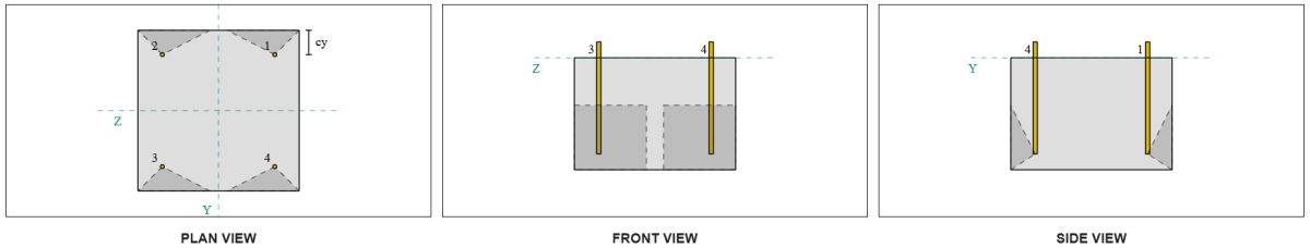
柱:
列部分: 他 240 乙
列区域: 10600 毫米2
列材料: S235
底盘:
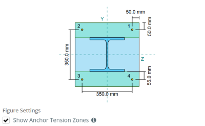
基板尺寸: 450 毫米× 450 毫米
基板厚度: 20 毫米
底板材料: S235
灌浆:
灌浆厚度: 20 毫米
具体:
混凝土尺寸: 500 毫米× 500 毫米
混凝土厚度: 350 毫米
混凝土材料: C25/30
破裂或无裂缝: 破裂
锚:
锚直径: 12 毫米
有效嵌入长度: 300.0 毫米
嵌入式板直径: 60 毫米
嵌入式板厚度: 10 毫米
锚材料: 8.8
其他信息:
- 非场合锚.
- 用切线的锚.
焊缝:
焊接类型: FPBW
填充金属分类: E35
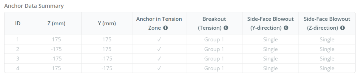
锚数据 (从 SkyCiv计算器):
SkyCiv 免费工具中的模型
立即使用我们的免费在线工具对上面的底板设计进行建模! 无需注册.
定义
锚张带:
在里面 SkyCiv 底板设计软件, 只有位于 锚张带 被认为有效抵抗提升. 该区域通常包括列法兰或网络附近的区域. 该区域以外的锚点不会导致抗拉力抵抗力,并且被排除在隆起计算之外.
该假设通过近似抬高力如何通过板来简化基板分析.
锚群:
的 SkyCiv 底板设计软件 包括一个直观的功能,该功能标识哪些锚定为评估的锚点组的一部分 混凝土突破 和 混凝土侧面井喷 失败.
一个 锚群 由具有相似有效嵌入深度和间距的多个锚组成, 并且足够近,以至于他们 预计电阻区重叠. 当锚分组时, 它们的能力合并以抵抗施加到该组的总张力.
不符合分组标准的锚被视为 单锚. 在这种情况下, 仅检查单个锚点上的张力力与其自身的有效阻力区域检查.
分步计算
检查一下 #1: 计算焊接容量
从给定的信息, 此设计示例中使用的焊缝是 完全穿透对接焊缝 (FPBW). 我们将计算柱和底板的碱金属能力,以确定焊接电阻. 去做这个, 我们首先需要计算 总焊接长度 在色谱柱上并获得焊接应力.
\(
F_{w,埃德} = frac{n_x}{2 B_F T_F + \剩下( d_{上校} – 2 T_F – 2 r_{上校} \对) t_w}
\)
\(
F_{w,埃德} = frac{50 \, \文本{千牛}}{2 \次 240 \, \文本{毫米} \次 17 \, \文本{毫米} + \剩下( 240 \, \文本{毫米} – 2 \次 17 \, \文本{毫米} – 2 \次 21 \, \文本{毫米} \对) \次 10 \, \文本{毫米}} = 5.102 \, \文本{兆帕}
\)
下一个, 我们确定 抗拉强度 色谱柱和底板之间的较弱的材料.
\(
f_y = min 左( F_{和,\文本{上校}}, F_{和,\文本{BP}} \对) = min left( 225 \, \文本{兆帕}, 225 \, \文本{兆帕} \对) = 225 \, \文本{兆帕}
\)
然后我们使用 在 1993-1-8:2005 条款 4.7.1 和 在 1993-1-1:2005 情商. 6.6 计算FPBW设计焊接阻力.
\(
F_{w,RD3} = frac{f_y}{\伽玛_{莫0}} = frac{225 \, \文本{兆帕}}{1} = 225 \, \文本{兆帕}
\)
以来 5.102 兆帕 < 225 兆帕, 焊接容量是 充足的.
检查一下 #2: 计算由于张力负载而导致的基本板弯曲屈服能力
计算 底板弯曲能力 反对张力负载, 我们将使用 产量线模式 例如圆形图案和非圆形图案. 然后, 我们确定能力, 假设没有撬动力, 通过比较板的屈服强度与锚螺栓的拉伸阻力.
开始, 我们计算所需的 方面 根据给定的螺栓布局. 参考 在 1992-1-8:2005 桌子 6.2 指导.
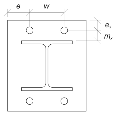
\(
m_x = frac{s_ – d_{上校}}{2} = frac{350 \, \文本{毫米} – 240 \, \文本{毫米}}{2} = 55 \, \文本{毫米}
\)
\(
w = s_z 左( n_{一个,\文本{边}} – 1 \对) = 350 \, \文本{毫米} \时代左( 2 – 1 \对) = 350 \, \文本{毫米}
\)
\(
e_x = frac{L_{BP} – s_}{2} = frac{450 \, \文本{毫米} – 350 \, \文本{毫米}}{2} = 50 \, \文本{毫米}
\)
\(
e = frac{b_{BP} – w}{2} = frac{450 \, \文本{毫米} – 350 \, \文本{毫米}}{2} = 50 \, \文本{毫米}
\)
\(
b_p = b_{BP} = 450 \, \文本{毫米}
\)
让我们还计算底板上的锚边缘距离, 受到的限制 \( m_x \) 尺寸
\(
n = min 左( 前任, 1.25 m_x 对) = min left( 50 \, \文本{毫米}, 1.25 \次 55 \, \文本{毫米} \对) = 50 \, \文本{毫米}
\)
然后, 我们计算以下的有效长度 圆形图案 (参考 科幻P398表 5.3).
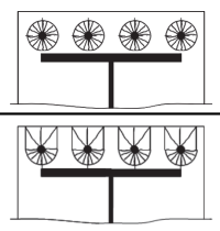
圆形图案 1:
\(
由使用公式计算的最小值控制{效果,CP1} = n_{一个,\文本{边}} \pi m_x = 2 \时代 pi times 55 \, \文本{毫米} = 345.58 \, \文本{毫米}
\)
圆形图案 2:
\(
由使用公式计算的最小值控制{效果,CP2} = 左( \压裂{n_{一个,\文本{边}}}{2} \对) (\pi m_x + 2 前任) = 左( \压裂{2}{2} \对) \次 (\pi times 55 \, \文本{毫米} + 2 \次 50 \, \文本{毫米}) = 272.79 \, \文本{毫米}
\)
管理圆形图案 有效长度:
\(
由使用公式计算的最小值控制{效果,cp} = min (由使用公式计算的最小值控制{效果,CP1}, 由使用公式计算的最小值控制{效果,CP2}) = min (345.58 \, \文本{毫米}, 272.79 \, \文本{毫米}) = 272.79 \, \文本{毫米}
\)
现在, 我们计算以下的有效长度 非圆形图案 (参考 科幻P398表 5.3)
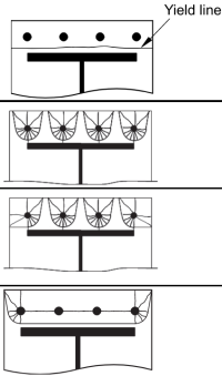
非圆形图案 1:
\(
由使用公式计算的最小值控制{效果,NC1} = frac{B_P}{2} = frac{450 \, \文本{毫米}}{2} = 225 \, \文本{毫米}
\)
非圆形图案 2:
\(
由使用公式计算的最小值控制{效果,NC2} = 左( \压裂{n_{一个,\文本{边}}}{2} \对) (4 m_x + 1.25 前任) = 左( \压裂{2}{2} \对) \次 (4 \次 55 \, \文本{毫米} + 1.25 \次 50 \, \文本{毫米}) = 282.5 \, \文本{毫米}
\)
非圆形图案 3:
\(
由使用公式计算的最小值控制{效果,NC3} = 2 m_x + 0.625 前任 + e = 2 \次 55 \, \文本{毫米} + 0.625 \次 50 \, \文本{毫米} + 50 \, \文本{毫米} = 191.25 \, \文本{毫米}
\)
非圆形图案 4:
\(
由使用公式计算的最小值控制{效果,NC4} = 2 m_x + 0.625 前任 + \压裂{(n_{一个,\文本{边}} – 1) S_Z}{2} = 2 \次 55 \, \文本{毫米} + 0.625 \次 50 \, \文本{毫米} + \压裂{(2 – 1) \次 350 \, \文本{毫米}}{2} = 316.25 \, \文本{毫米}
\)
管理非圆形图案 有效长度:
\(
由使用公式计算的最小值控制{效果,NC} = min (由使用公式计算的最小值控制{效果,NC1}, 由使用公式计算的最小值控制{效果,NC2}, 由使用公式计算的最小值控制{效果,NC3}, 由使用公式计算的最小值控制{效果,NC4}) = min (225 \, \文本{毫米}, 282.5 \, \文本{毫米}, 191.25 \, \文本{毫米}, 316.25 \, \文本{毫米}) = 191.25 \, \文本{毫米}
\)
然后, 我们确定圆形图案和非圆形图案的有效长度之间的值较小.
\(
由使用公式计算的最小值控制{效果,1} = min (由使用公式计算的最小值控制{效果,cp}, 由使用公式计算的最小值控制{效果,NC}) = min (272.79 \, \文本{毫米}, 191.25 \, \文本{毫米}) = 191.25 \, \文本{毫米}
\)
现在, 我们使用此计算的有效长度来计算其弯曲屈服阻力. 根据 在 1993-1-8:2005 桌子 6.2, 故障模式的板矩阻力 1 是:
\(
M_{PL,1,路} = frac{0.25 由使用公式计算的最小值控制{效果,1} (t_{BP})^2 f_{和 _bp}}{\伽玛_{莫0}} = frac{0.25 \次 191.25 \, \文本{毫米} \次 (20 \, \文本{毫米})^2 times 225 \, \文本{兆帕}}{1} = 4303.1 \, \文本{千牛} \CDOT text{毫米}
\)
假设 不撬, 我们使用en 1993-1-8:2005 桌子 6.2 确定 设计 底板的抗性 失败 模式 1 和 2.
\(
F_{Ť,1,路} = frac{2 M_{PL,1,路}}{m_x} = frac{2 \次 4303.1 \, \文本{千牛} \CDOT text{毫米}}{55 \, \文本{毫米}} = 156.48 \, \文本{千牛}
\)
然后, 我们使用 在 1992-4:2018 条款 7.2.1.3. 随后的锚检查将进一步详细说明.
\(
F_{Ť,路} = frac{c k_2 f_{u _anc} 作为}{\伽玛_{M2,锚}} = frac{0.85 \次 0.9 \次 800 \, \文本{兆帕} \次 113.1 \, \文本{毫米}^ 2}{1.25} = 55.372 \, \文本{千牛}
\)
然后,我们将使用每个锚杆的电阻来计算 底板的设计抵抗力 失败 模式 3, 这是总螺栓故障.
\(
F_{Ť,3,路} = n_{一个,边} F_{Ť,路} = 2 \次 55.372 \, \文本{千牛} = 110.74 \, \文本{千牛}
\)
最后, 我们确定故障模式之间的电阻值.
\(
F_{Ť,路} = min (F_{Ť,1,路}, F_{Ť,3,路}) = min (156.48 \, \文本{千牛}, 110.74 \, \文本{千牛}) = 110.74 \, \文本{千牛}
\)
计算 每个法兰的张力负载, 我们有:
\(
F_{Ť,埃德} = frac{n_x}{2} = frac{50 \, \文本{千牛}}{2} = 25 \, \文本{千牛}
\)
以来 25 千牛 < 110.74 千牛, 基板弯曲屈服能力为 充足的.
检查一下 #3: 计算锚杆拉伸能力
我们已经知道锚杆拉伸能力的价值, 但是,让我们更详细地解决.
第一, 让我们计算锚杆的拉伸应力区域.
\(
A_s = frac{\pi}{4} (d_{无})^2 = frac{\pi}{4} \次 (12 \, \文本{毫米})可以假设为 113.1 \, \文本{毫米}^ 2
\)
然后, 让我们使用 \( C \) 因素和 \( 钢底板设计欧洲规范{2} \) 因素. 这些值可以在SkyCiv底板设计软件的设置中进行修改. 在这里尝试免费版本.
- \( c = 0.85 \) 对于带有切线的锚
- \( 钢底板设计欧洲规范{2} = 0.9\) 用于非官能锚
现在, 让我们使用 在 1992-4:2018 条款 7.2.1.3 计算 锚杆的设计抵抗力 紧张中.
\(
N_{路,s} = frac{c k_2 f_{u _anc} 作为}{\伽玛_{M2,锚}} = frac{0.85 \次 0.9 \次 800 \, \文本{兆帕} \次 113.1 \, \文本{毫米}^ 2}{1.25} = 55.372 \, \文本{千牛}
\)
计算 每个锚的张力负载, 我们有:
\(
N_{埃德} = frac{n_x}{n_{一个,Ť}} = frac{50 \, \文本{千牛}}{4} = 12.5 \, \文本{千牛}
\)
以来 12.5 千牛 < 55.372 千牛, 锚杆拉伸能力为 充足的.
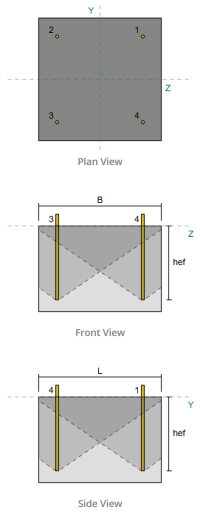
检查一下 #4: 计算张力的混凝土突破能力
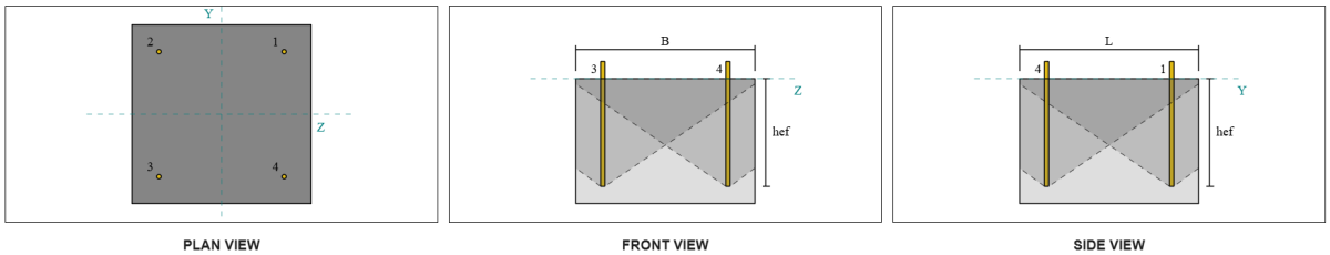
在计算突破能力之前, 我们必须首先确定成员是否有资格 狭窄的成员. 根据 在 1992-4:2008 条款 7.2.1.4(8), 该成员符合狭窄成员的标准. 因此, 一个 修改的 有效嵌入长度 必须用于分解能力计算. 这种调整也影响 特征间距 和 特征边缘距离, 必须相应修改.
根据狭窄的成员标准, 的 修改值 对于锚组如下:
- 修改的有效嵌入长度, \( h__{ef} = 100 毫米 \)
- 修改的特征间距, \( s{铬} = 300 毫米)
- 修改的特征边缘距离, \( c’_{铬} = 150 毫米)
使用 在 1992-4:2018 情商. 7.3, 我们计算 参考投影混凝土锥体区域 对于单个锚点.
\(
A0_{C,ñ} = s’_{铬,G1} s{铬,G1} = 350 \, \文本{毫米} \次 350 \, \文本{毫米} = 122500 \, \文本{毫米}^ 2
\)
相似地, 我们计算 实际投影混凝土锥体 锚群.
\(
一个_{数控} = l_{数控} b_{数控} = 500 \, \文本{毫米} \次 500 \, \文本{毫米} = 250000 \, \文本{毫米}^ 2
\)
在哪里,
\(
L_{数控} = min left( C_{剩下,G1}, c’_{铬,G1} \对)
+ \剩下( \最小左( s_{和,与,G1}, s{铬,G1} \剩下( n_{与,G1} – 1 \对) \对) \对)
+ \最小左( C_{对,G1}, c’_{铬,G1} \对)
\)
\(
L_{数控} = min left( 75 \, \文本{毫米}, 175 \, \文本{毫米} \对)
+ \剩下( \最小左( 350 \, \文本{毫米}, 350 \, \文本{毫米} \次 (2 – 1) \对) \对)
+ \最小左( 75 \, \文本{毫米}, 175 \, \文本{毫米} \对)
\)
\(
L_{数控} = 500 \, \文本{毫米}
\)
\(
b_{数控} = min left( C_{最佳,G1}, c’_{铬,G1} \对)
+ \剩下( \最小左( s_{和,和,G1}, s{铬,G1} \剩下( n_{和,G1} – 1 \对) \对) \对)
+ \最小左( C_{底部,G1}, c’_{铬,G1} \对)
\)
\(
b_{数控} = min left( 75 \, \文本{毫米}, 175 \, \文本{毫米} \对)
+ \剩下( \最小左( 350 \, \文本{毫米}, 350 \, \文本{毫米} \次 (2 – 1) \对) \对)
+ \最小左( 75 \, \文本{毫米}, 175 \, \文本{毫米} \对)
\)
\(
b_{数控} = 500 \, \文本{毫米}
\)
下一个, 我们评估 特征强度 使用一个锚 在 1992-4:2018 情商. 7.2
\(
n0_{检查锚容量,C} = k_1 开方{\压裂{F_{钢底板设计欧洲规范}}{\文本{兆帕}}} \剩下( \压裂{h__{ef,G1}}{\文本{毫米}} \对)^{1.5} ñ
\)
\(
n0_{检查锚容量,C} = 8.9 \次 sqrt{\压裂{25 \, \文本{兆帕}}{1 \, \文本{兆帕}}} \时代左( \压裂{116.67 \, \文本{毫米}}{1 \, \文本{毫米}} \对)^{1.5} \次 0.001 \, \文本{千牛} = 56.076 \, \文本{千牛}
\)
在哪里,
- \(钢底板设计欧洲规范{1} = 8.9\) 用于预制锚栓
现在, 我们通过计算必要的 参数 对于突破性阻力.
锚固组的最短边缘距离确定为:
\(
C_{分,ñ} = min left( C_{剩下,G1}, C_{对,G1}, C_{最佳,G1}, C_{底部,G1} \对)
= min left( 87.5 \, \文本{毫米}, 87.5 \, \文本{毫米}, 150 \, \文本{毫米}, 150 \, \文本{毫米} \对)
= 87.5 \, \文本{毫米}
\)
根据 在 1992-4:2018 情商. 7.4, 参数的值核算混凝土中应力分布的值为:
\(
\psi_{s,ñ} = min left( 0.7 + 0.3 \剩下( \压裂{C_{分,ñ}}{c’_{铬,G1}} \对), 1.0 \对)
= min left( 0.7 + 0.3 \时代左( \压裂{75 \, \文本{毫米}}{175 \, \文本{毫米}} \对), 1 \对)
= 0.82857
\)
的 壳剥落效果 用于使用 在 1992-4:2018 情商. 7.5, 给予:
\(
\psi_{检查锚容量,ñ} = min left( 0.5 + \压裂{h__{ef,G1}}{\文本{毫米} \, / \, 200}, 1.0 \对)
= min left( 0.5 + \压裂{116.67 \, \文本{毫米}}{1 \, \文本{毫米} \, / \, 200}, 1 \对)
= 1
\)
此外, 两者 偏心率因子 和 压缩影响因子 被视为:
\(
\psi_{欧共体,ñ} = 1
\)
\(
\psi_{m,ñ} = 1
\)
然后,我们结合了所有这些因素,并应用 作为 5216:2021 方程 6.2.3.1 评估 设计混凝土锥体突破性阻力 对于锚点:
\(
N_{路,C} = frac{n0_{检查锚容量,C} \剩下( \压裂{一个_{数控}}{A0_{C,ñ}} \对) \psi_{s,ñ} \psi_{检查锚容量,ñ} \psi_{欧共体,ñ} \psi_{m,ñ}}{\伽玛_{检查锚容量}}
\)
\(
N_{路,C} = frac{56.076 \, \文本{千牛} \时代左( \压裂{250000 \, \文本{毫米}^ 2}{122500 \, \文本{毫米}^ 2} \对) \次 0.82857 \次 1 \次 1 \次 1}{1.5} = 63.215 \, \文本{千牛}
\)
的 总施加负荷 在锚点上,通过将每个锚的张力负载乘以锚数来计算:
\(
N_{fa} = 左( \压裂{n_x}{n_{一个,Ť}} \对) n_{一个,G1} = 左( \压裂{50 \, \文本{千牛}}{4} \对) \次 4 = 50 \, \文本{千牛}
\)
以来 50 千牛 < 63.215 千牛 具体的突破能力是 充足的.
检查一下 #5: 计算锚推拉力
的 拔出能力 锚点的嵌入端受阻力支配. 开始, 我们计算 轴承区 嵌入式板的, 减去锚杆占用的区域后,这是净区域.
第一, 我们计算有效拉出电阻有效的最大锚头维, 按照 在 1992-4:2018 条款 7.2.1.5 注意.
\(
d_{H,\文本{最高}} = min left( b_{\文本{嵌入 _ plate}}, 6 \剩下( t_{\文本{嵌入 _ plate}} \对) + d_{\文本{无}} \对)
= min left( 60 \, \文本{毫米}, 6 \次 (10 \, \文本{毫米}) + 12 \, \文本{毫米} \对)
= 60 \, \文本{毫米}
\)
下一个, 我们使用:
\(
一个_{brg} = frac{\pi}{4} \剩下( \剩下( d_{H,\文本{最高}} \对)^ 2 – \剩下( d_{\文本{无}} \对)^2 对)
\)
\(
一个_{brg} = frac{\pi}{4} \时代左( \剩下( 60 \, \文本{毫米} \对)^ 2 – \剩下( 12 \, \文本{毫米} \对)^2 对) = 2714.3 \, \文本{毫米}^ 2
\)
然后我们计算 设计具体的拔出电阻 使用的施加锚在紧张中 在 1992-4:2018 条款 7.2.1.5:
\(
N_{路,s} = frac{k_2 a_{brg} F_{钢底板设计欧洲规范}}{\伽玛_{MP}}
= frac{7.5 \次 2714.3 \, \文本{毫米}^2 times 25 \, \文本{兆帕}}{1.5}
= 339.29 \, \文本{千牛}
\)
回想先前计算的 每个锚的张力负载:
\(
N_{埃德} = frac{n_x}{n_{一个,Ť}} = frac{50 \, \文本{千牛}}{4} = 12.5 \, \文本{千牛}
\)
以来 12.5 千牛 < 339.29 千牛, 锚推拔出能力是 充足的.
检查一下 #6: 计算Y方向的侧面井喷容量

让我们考虑锚固ID #3. 我们首先计算到边缘距离到达 故障边缘.
\(
C_{与,\文本{分}} = min left( C_{\文本{剩下,s3}}, C_{\文本{对,s3}} \对)
= min left( 75 \, \文本{毫米}, 425 \, \文本{毫米} \对)
= 75 \, \文本{毫米}
\)
下一个, 我们确定边缘距离到 正交边缘.
\(
C_{和,\文本{分}} = min left( C_{\文本{最佳,s3}}, C_{\文本{底部,s3}} \对)
= min left( 425 \, \文本{毫米}, 75 \, \文本{毫米} \对)
= 75 \, \文本{毫米}
\)
使用 在 1992-4:2018 情商. 7.27, 让我们计算 参考投影区域 一个紧固件.
\(
A0_{C,NB} = 左( 4 C_{与,\文本{分}} \对)^ 2
= 左( 4 \次 75 \, \文本{毫米} \对)^ 2
= 90000 \, \文本{毫米}^ 2
\)
由于我们正在检查锚群的容量, 让我们得到 实际投影区域 使用锚群使用 在 1992-4:2018 情商. 7.27.
\(
一个_{数控} = b_{C,NB} H_{C,NB} = 225 \, \文本{毫米} \次 200 \, \文本{毫米} = 45000 \, \文本{毫米}^ 2
\)
在哪里,
\(
b_{C,NB} = 2 C_{与,\文本{分}} + \最小左( 2 C_{与,\文本{分}}, C_{和,\文本{分}} \对)
= 2 \次 75 \, \文本{毫米} + \最小左( 2 \次 75 \, \文本{毫米}, 75 \, \文本{毫米} \对)
= 225 \, \文本{毫米}
\)
\(
H_{C,NB} = 2 C_{与,\文本{分}} + \剩下( \最小左( t_{\文本{浓}} – H_{\文本{ef}}, 2 C_{与,\文本{分}} \对) \对)
= 2 \次 75 \, \文本{毫米} + \剩下( \最小左( 350 \, \文本{毫米} – 300 \, \文本{毫米}, 2 \次 75 \, \文本{毫米} \对) \对)
= 200 \, \文本{毫米}
\)
在计算 特征具体的爆破强度 个体锚的, 我们将使用 在 1992-4:2018 情商. 7.26.
\(
n0_{检查锚容量,CB} = k_5 左( \压裂{C_{与,\文本{分}}}{\文本{毫米}} \对)
\剩下( \sqrt{\压裂{一个_{\文本{brg}}}{\文本{毫米}^ 2}} \对)
\剩下( \sqrt{\压裂{F_{钢底板设计欧洲规范}}{\文本{兆帕}}} \对) ñ
\)
\(
n0_{检查锚容量,CB} = 8.7 \时代左( \压裂{75 \, \文本{毫米}}{1 \, \文本{毫米}} \对)
\时代左( \sqrt{\压裂{2714.3 \, \文本{毫米}^ 2}{1 \, \文本{毫米}^ 2}} \对)
\时代左( \sqrt{\压裂{25 \, \文本{兆帕}}{1 \, \文本{兆帕}}} \对)
\次 0.001 \, \文本{千牛}
\)
\(
n0_{检查锚容量,CB} = 169.97 \, \文本{千牛}
\)
然后, 我们会得到 侧面井喷参数.
可以根据混凝土中应力分布的干扰的参数可以根据 在 1992-4:2018 情商. 7.28.
\(
\psi_{s,NB} = min left( 0.7 + 0.3 \剩下( \压裂{C_{和,\文本{分}}}{2 C_{与,\文本{分}}} \对), 1.0 \对)
= min left( 0.7 + 0.3 \时代左( \压裂{75 \, \文本{毫米}}{2 \次 75 \, \文本{毫米}} \对), 1 \对)
= 0.85
\)
此外, 群体效应的因素和因素的影响偏心率的影响如下:
\(
\psi_{G,NB} = 1
\)
\(
\psi_{欧共体,ñ} = 1
\)
最后, 参考 作为 5216:2021 情商. 6.2.7 用于头锚杆, 的 设计具体的爆破抵抗 是:
\(
N_{检查锚容量,CB} = frac{n0_{检查锚容量,CB} \剩下( \压裂{一个_{数控}}{A0_{C,NB}} \对) \剩下( \psi_{s,NB} \对) \剩下( \psi_{G,NB} \对) \剩下( \psi_{欧共体,ñ} \对)}{\伽玛_{检查锚容量}}
\)
\(
N_{检查锚容量,CB} = frac{169.97 \, \文本{千牛} \时代左( \压裂{45000 \, \文本{毫米}^ 2}{90000 \, \文本{毫米}^ 2} \对) \时代左( 0.85 \对) \时代左( 1 \对) \时代左( 1 \对)}{1.5} = 48.159 \, \文本{千牛}
\)
记起 每个锚的张力负载:
\(
N_{埃德} = frac{n_x}{n_{一个,Ť}} = frac{50 \, \文本{千牛}}{4} = 12.5 \, \文本{千牛}
\)
以来 12.5 千牛 < 48.159 千牛, 沿y方向的混凝土侧面井喷为 充足的.
任何其他锚ID号也可以使用,并产生相同的结果, 由于设计是对称的.
检查一下 #7: 计算Z方向的侧面井喷容量
在计算z方向的侧面井喷的能力时,使用了相同的过程. 让我们考虑锚固ID #2 这次. 再次, 我们首先计算到边缘距离到达 故障边缘.
\(
C_{和,\文本{分}} = min left( C_{\文本{最佳},s2}, C_{\文本{底部},s2} \对)
= min left( 75 \, \文本{毫米}, 425 \, \文本{毫米} \对)
= 75 \, \文本{毫米}
\)
下一个, 我们确定边缘距离到 正交边缘.
\(
C_{与,\文本{分}} = min left( C_{\文本{剩下},s2}, C_{\文本{对},s2} \对)
= min left( 75 \, \文本{毫米}, 425 \, \文本{毫米} \对)
= 75 \, \文本{毫米}
\)
使用 在 1992-4:2018 情商. 7.27, 让我们计算 参考投影区域 一个紧固件.
\(
A0_{C,NB} = 左( 4 C_{和,\文本{分}} \对)^ 2
= 左( 4 \次 75 \, \文本{毫米} \对)^ 2
= 90000 \, \文本{毫米}^ 2
\)
由于我们正在检查锚群的容量, 让我们得到 实际投影区域 使用锚群使用 在 1992-4:2018 情商. 7.27.
\(
一个_{数控} = b_{C,NB} H_{C,NB}
= 225 \, \文本{毫米} \次 200 \, \文本{毫米}
= 45000 \, \文本{毫米}^ 2
\)
在哪里,
\(
b_{C,NB} = 2 C_{和,\文本{分}} + \最小左( 2 C_{和,\文本{分}}, C_{与,\文本{分}} \对)
= 2 \次 75 \, \文本{毫米} + \最小左( 2 \次 75 \, \文本{毫米}, 75 \, \文本{毫米} \对)
= 225 \, \文本{毫米}
\)
\(
H_{C,NB} = 2 C_{和,\文本{分}} + \剩下( \最小左( t_{\文本{浓}} – H_{\文本{ef}}, 2 C_{和,\文本{分}} \对) \对)
= 2 \次 75 \, \文本{毫米} + \剩下( \最小左( 350 \, \文本{毫米} – 300 \, \文本{毫米}, 2 \次 75 \, \文本{毫米} \对) \对)
= 200 \, \文本{毫米}
\)
在计算 特征具体的爆破强度 个体锚的, 我们将使用 在 1992-4:2018 情商. 7.26.
\(
n0_{检查锚容量,CB} = k_5 左( \压裂{C_{和,\文本{分}}}{\文本{毫米}} \对)
\sqrt{\剩下( \压裂{一个_{brg}}{\文本{毫米}^ 2} \对)}
\sqrt{\剩下( \压裂{F_{钢底板设计欧洲规范}}{\文本{兆帕}} \对)} \, \文本{ñ}
\)
\(
n0_{检查锚容量,CB} = 8.7 \剩下( \压裂{75 \, \文本{毫米}}{1 \, \文本{毫米}} \对)
\sqrt{\剩下( \压裂{2714.3 \, \文本{毫米}^ 2}{1 \, \文本{毫米}^ 2} \对)}
\sqrt{\剩下( \压裂{25 \, \文本{兆帕}}{1 \, \文本{兆帕}} \对)}
\点 0.001 \, \文本{千牛}
\)
\(
n0_{检查锚容量,CB} = 169.97 \, \文本{千牛}
\)
然后, 我们会得到 侧面井喷参数.
可以根据混凝土中应力分布的干扰的参数可以根据 在 1992-4:2018 情商. 7.28.
\(
\psi_{s,NB} = min left( 0.7 + 0.3 \剩下( \压裂{C_{与,\文本{分}}}{2 C_{和,\文本{分}}} \对), 1.0 \对)
= min left( 0.7 + 0.3 \时代左( \压裂{75 \, \文本{毫米}}{2 \次 75 \, \文本{毫米}} \对), 1 \对)
= 0.85
\)
此外, 群体效应的因素和因素的影响偏心率的影响如下:
\(
\psi_{G,NB} = 1
\)
\(
\psi_{欧共体,ñ} = 1
\)
最后, 参考 作为 5216:2021 情商. 6.2.7 用于头锚杆, 的 设计具体的爆破抵抗 是:
记起 每个锚的张力负载:
\(
N_{埃德} = frac{n_x}{n_{一个,Ť}} = frac{50 \, \文本{千牛}}{4} = 12.5 \, \文本{千牛}
\)
以来 12.5 千牛 < 48.159 千牛, 沿z方向的混凝土侧面井喷为 充足的.
任何其他锚ID号也可以使用,并产生相同的结果, 由于设计是对称的.
设计概要
的 SkyCiv底板设计软件 可以自动为此设计示例生成逐步计算报告. 它还提供了执行的检查及其结果比率的摘要, 一目了然地使信息易于理解. 以下是示例摘要表, 报告中包括.
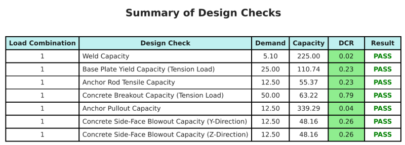
SkyCiv样本报告
查看 SkyCiv 底板设计报告的详细程度和清晰度. 该报告包括所有关键的设计检查, 方程式, 并以清晰易读的格式呈现结果. 完全符合设计标准. 单击下面查看使用 SkyCiv 底板计算器生成的示例报告.
购买基板软件
单独购买基本板设计模块的完整版本,而没有任何其他SkyCiv模块. 这为您提供了底板设计的完整结果, 包括详细报告和更多功能.