使用CSA S16的底板设计示例:19 和CSA A23.3:19
问题陈述
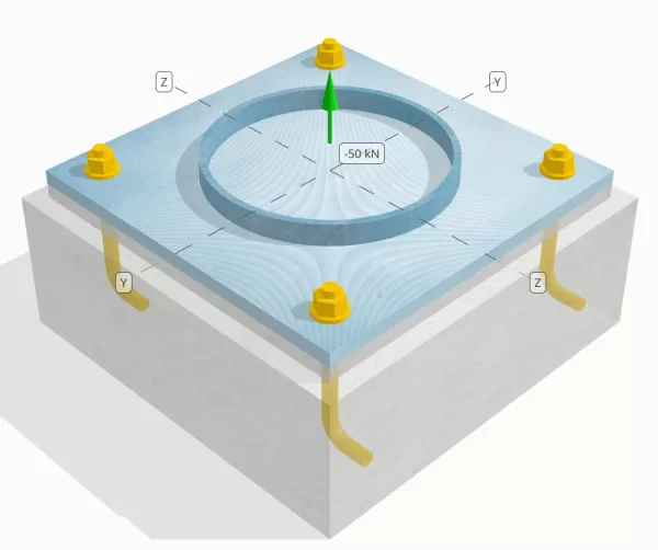
确定设计的列板连接是否足以满足50k的张力负载.
给定数据
柱:
列部分: HS324x9.5
列区域: 9410 毫米2
列材料: 230G
底盘:
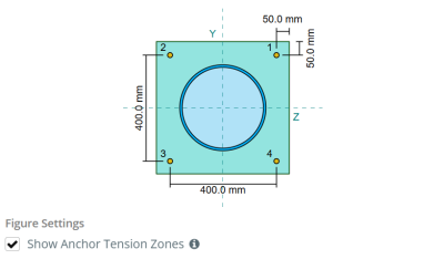
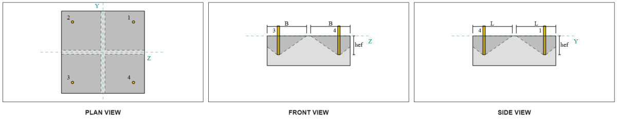
基板尺寸: 500 毫米× 500 毫米
基板厚度: 20 毫米
底板材料: 230G
灌浆:
灌浆厚度: 20 毫米
具体:
混凝土尺寸: 550 毫米× 550 毫米
混凝土厚度: 200 毫米
混凝土材料: 20.68 兆帕
破裂或无裂缝: 破裂
锚:
锚直径: 19.1 毫米
有效嵌入长度: 130.0 毫米
钩长: 60毫米
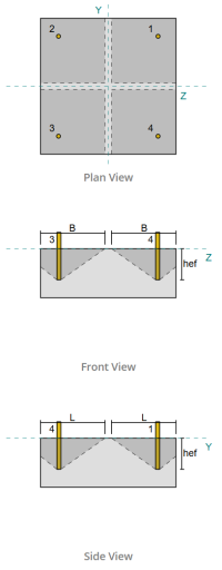
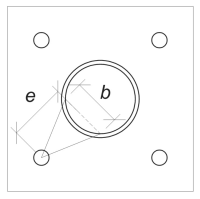
锚偏移距离列的距离: 120.84 毫米
焊缝:
焊接类型: CJP
填充金属分类: E43xx
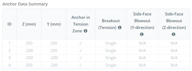
锚数据 (从 SkyCiv计算器):
SkyCiv 免费工具中的模型
立即使用我们的免费在线工具对上面的底板设计进行建模! 无需注册.
定义
负载路径:
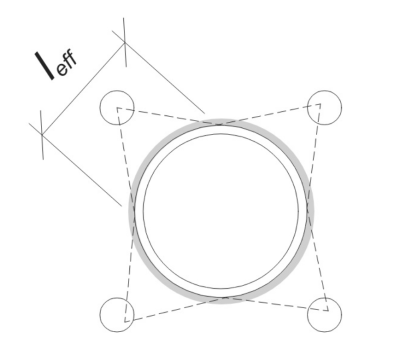
当底板受到抬高时 (拉伸) 军队, 这些力被转移到锚杆上, 这反过. 弯曲动作可以看到为 悬臂弯曲 发生在列的法兰或网络周围, 取决于锚定位的位置.
在里面 SkyCiv 底板设计软件, 只有位于 锚张带 被认为有效抵抗提升. 该区域通常包括列法兰或网络附近的区域. 如果是 圆柱, 锚点张力区包括圆柱外部的整个区域. 该区域以外的锚点不会导致抗拉力抵抗力,并且被排除在隆起计算之外.
确定基本板的有效区域,以抵抗弯曲, 一个 45-学位分散 从每个锚杆的中心线朝向圆柱面假设. 这个分散定义了 有效的焊接长度 并帮助建立 有效的弯曲宽度 盘子的.
该假设通过近似抬高力如何通过板来简化基板分析.
锚群:
的 SkyCiv 底板设计软件 包括一个直观的功能,该功能标识哪些锚定为评估的锚点组的一部分 混凝土突破 和 混凝土侧面井喷 失败.
一个 锚群 由具有相似有效嵌入深度和间距的多个锚组成, 并且足够近,以至于他们 预计电阻区重叠. 当锚分组时, 它们的能力合并以抵抗施加到该组的总张力.
不符合分组标准的锚被视为 单锚. 在这种情况下, 仅检查单个锚点上的张力力与其自身的有效阻力区域检查.
分步计算
检查一下 #1: 计算焊接容量
开始, 我们需要计算每个锚的负载并确定每个锚的有效焊接长度. 的 有效的焊接长度 是基于 45°分散线 从锚的中心到柱面. 如果此45°线不相交, 的 切线 改用. 另外, 如果锚距离紧密, 有效的焊接长度降低以避免重叠. 最后, 所有有效的焊接长度的总和不得超过沿圆柱周长可用的实际可焊接长度.
让我们将其应用于我们的榜样. 基于给定的几何形状, 来自锚的45°线不会与色谱柱相交. 结果是, 而是使用切线之间的弧长. 该电弧长度还必须考虑到任何相邻的锚, 减去任何重叠部分以避免双重计数. 计算出的电弧长度为:
\(
由使用公式计算的最小值控制{\文本{弧}} = 254.47 \, \文本{毫米}
\)
此电弧长度计算在SkyCiv基板设计软件中完全自动化, 但也可以使用三角法手动执行. 您可以尝试此链接的免费工具.
考虑沿圆柱的可用焊接长度, 决赛 有效的焊接长度 是:
\(
由使用公式计算的最小值控制{\文本{效果}} = min left( 由使用公式计算的最小值控制{\文本{弧}}, \压裂{\pi d_{\文本{上校}}}{n_{一个,Ť}} \对) = min left( 254.47 \, \文本{毫米}, \压裂{\pi times 324 \, \文本{毫米}}{4} \对) = 254.47 \, \文本{毫米}
\)
下一个, 让我们计算 每个锚负载. 给定的四组 (4) 锚点, 每个锚的负载是:
\(
T_{ü,\文本{锚}} = frac{n_x}{n_{一个,Ť}} = frac{50 \, \文本{千牛}}{4} = 12.5 \, \文本{千牛}
\)
使用计算的有效焊接长度, 我们现在可以计算 每单位长度所需的力 在焊接上作用.
\(
v_f = frac{T_{ü,\文本{锚}}}{由使用公式计算的最小值控制{\文本{效果}}} = frac{12.5 \, \文本{千牛}}{254.47 \, \文本{毫米}} = 0.049122 \, \文本{千牛/毫米}
\)
现在, 我们指的是 CSA S16:19 条款 13.13.3.1 计算 分考虑了完全关节穿透的抵抗力 (CJP) 焊接. 这需要碱金属电阻, 按单位长度表示, 对于色谱柱和底板材料.
\(
v_{[R,\文本{BM}} = phi 左( \最小左( F_{和,\文本{上校}} t_{\文本{上校}}, F_{和,\文本{BP}} t_{\文本{BP}} \对) \对)
\)
\(
v_{[R,\文本{BM}} = 0.9 \时代左( \最小左( 230 \, \文本{兆帕} \次 9.53 \, \文本{毫米}, 230 \, \文本{兆帕} \次 20 \, \文本{毫米} \对) \对) = 1.9727 \, \文本{千牛/毫米}
\)
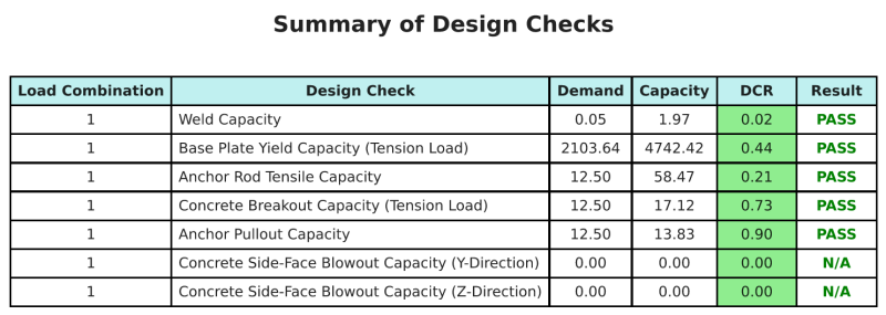
以来 0.049122 千牛/毫米 < 1.9727 千牛/毫米, 焊接容量是 充足的.
检查一下 #2: 计算由于张力负载而导致的基本板弯曲屈服能力
使用每个锚和 偏移距离 从锚的中心到柱面, 应用于基板的力矩可以使用 悬臂 假设. 对于圆柱, 负载偏心率是通过考虑焊接弧的射手来确定的, 可以计算如下:
\(
e_{\文本{管道}} = D_O + r_{\文本{上校}} \剩下( 1 – \因为左( \压裂{由使用公式计算的最小值控制{\文本{效果}}}{2 r_{\文本{上校}}} \对) \对)
\)
\(
e_{\文本{管道}} = 120.84 \, \文本{毫米} + 162 \, \文本{毫米} \时代左( 1 – \因为左( \压裂{254.47 \, \文本{毫米}}{2 \次 162 \, \文本{毫米}} \对) \对) = 168.29 \, \文本{毫米}
\)
诱导力矩计算为:
\(
m_f = t_{ü,\文本{锚}} e_{\文本{管道}} = 12.5 \, \文本{千牛} \次 168.29 \, \文本{毫米} = 2103.6 \, \文本{千牛} \CDOT text{毫米}
\)
下一个, 我们将确定底板的弯曲宽度. 为了这, 我们使用 和弦长度 对应于有效焊接弧.
\(
\theta_{\文本{工作}} = frac{由使用公式计算的最小值控制{\文本{效果}}}{0.5 d_{\文本{上校}}} = frac{254.47 \, \文本{毫米}}{0.5 \次 324 \, \文本{毫米}} = 1.5708
\)
\(
b = d_{\文本{上校}} \剩下( \罪左( \压裂{\theta_{\文本{工作}}}{2} \对) \对) = 324 \, \文本{毫米} \时代左( \罪左( \压裂{1.5708}{2} \对) \对) = 229.1 \, \文本{毫米}
\)
最后, 我们可以计算 归纳 弯曲阻力 使用底板的 CSA S16:19 条款 13.5.
\(
m_r = phi f_{和,\文本{BP}} z_{\文本{效果}} = 0.9 \次 230 \, \文本{兆帕} \次 22910 \, \文本{毫米}^3 = 4742.4 \, \文本{千牛} \CDOT text{毫米}
\)
在哪里,
\(
z_{\文本{效果}} = frac{b (t_{\文本{BP}})^ 2}{4} = frac{229.1 \, \文本{毫米} \次 (20 \, \文本{毫米})^ 2}{4} = 22910 \, \文本{毫米}^ 3
\)
以来 2103.6 kn-mm < 4742.4 kn-mm, 基板弯曲屈服能力为 充足的.
检查一下 #3: 计算锚杆拉伸能力
评估锚杆的拉伸能力, 我们指的是CSA A23.3:19 第D.6.1.2和CSA S16条款:19 条款 25.3.2.1.
第一, 我们确定 指定的拉伸强度 锚钢. 这是允许的最低值 CSA A23.3:19 第D.6.1.2条款.
\(
F_{\文本{乌塔}} = min left( F_{ü,\文本{无}}, 1.9 F_{和,\文本{无}}, 860 \对) = min left( 400 \, \文本{兆帕}, 1.9 \次 248.2 \, \文本{兆帕}, 860.00 \, \文本{兆帕} \对) = 400 \, \文本{兆帕}
\)
下一个, 我们确定 有效的横截面区域 使用锚杆的紧张 CAC混凝土设计手册, 3RD版, 桌子 12.3.
\(
一个_{我知道,ñ} = 215 \, \文本{毫米}^ 2
\)
这些值, 我们申请 CSA A23.3:19 情商. D.2 计算 考虑了拉伸阻力 锚杆.
\(
N_{\文本{sar}} = A_{我知道,ñ} \phi_s f_{\文本{乌塔}} R = 215 \, \文本{毫米}^2 times 0.85 \次 400 \, \文本{兆帕} \次 0.8 = 58.465 \, \文本{千牛}
\)
另外, 我们评估 考虑了拉伸阻力 根据 CSA S16:19 条款 25.3.2.1.
\(
t_r = phi_{ar} 0.85 一个_{ar} F_{ü,\文本{无}} = 0.67 \次 0.85 \次 285.02 \, \文本{毫米}^2 times 400 \, \文本{兆帕} = 64.912 \, \文本{千牛}
\)
比较两者之后, 我们确定使用CSA A23.3计算的分解电阻:19 在这种情况下管理.
回想先前计算的 每个锚的张力负载:
\(
N_{fa} = frac{n_x}{n_{一个,Ť}} = frac{50 \, \文本{千牛}}{4} = 12.5 \, \文本{千牛}
\)
以来 12.5 千牛 < 58.465 千牛, 锚杆拉伸能力为 充足的.
检查一下 #4: 计算张力的混凝土突破能力
在计算突破能力之前, 我们必须首先确定成员是否有资格 狭窄的成员. 根据 CSA A23.3:19 第D.6.2.3条款, 该成员不符合狭窄成员的标准. 因此, 给定 有效嵌入长度 将用于计算.
使用 CSA A23.3:19 情商. D.5, 我们计算 最大投影混凝土锥体区域 对于单个锚点, 基于有效嵌入长度.
\(
一个_{记住} = 9 (H_{ef,s1})可以假设为 9 \次 (130 \, \文本{毫米})可以假设为 152100 \, \文本{毫米}^ 2
\)
相似地, 我们使用有效的嵌入长度来计算 实际投影混凝土锥体 单锚.
\(
一个_{数控} = l_{数控} b_{数控} = 270 \, \文本{毫米} \次 270 \, \文本{毫米} = 72900 \, \文本{毫米}^ 2
\)
在哪里,
\(
L_{数控} = 左( \最小左( C_{\文本{剩下},s1}, 1.5 H_{ef,s1} \对) \对) + \剩下( \最小左( C_{\文本{对},s1}, 1.5 H_{ef,s1} \对) \对)
\)
\(
L_{数控} = 左( \最小左( 475 \, \文本{毫米}, 1.5 \次 130 \, \文本{毫米} \对) \对) + \剩下( \最小左( 75 \, \文本{毫米}, 1.5 \次 130 \, \文本{毫米} \对) \对)
\)
\(
L_{数控} = 270 \, \文本{毫米}
\)
\(
b_{数控} = 左( \最小左( C_{\文本{最佳},s1}, 1.5 H_{ef,s1} \对) \对) + \剩下( \最小左( C_{\文本{底部},s1}, 1.5 H_{ef,s1} \对) \对)
\)
\(
b_{数控} = 左( \最小左( 75 \, \文本{毫米}, 1.5 \次 130 \, \文本{毫米} \对) \对) + \剩下( \最小左( 475 \, \文本{毫米}, 1.5 \次 130 \, \文本{毫米} \对) \对)
\)
\(
b_{数控} = 270 \, \文本{毫米}
\)
下一个, 我们评估 归纳 基本的混凝土突破性抵抗力 使用一个锚 CSA A23.3:19 情商. D.6
\(
N_{br} = k_c phi lambda_a sqrt{\压裂{f'_c}{\文本{兆帕}}} \剩下( \压裂{H_{ef,s1}}{\文本{毫米}} \对)^{1.5} r n
\)
\(
N_{br} = 10 \次 0.65 \次 1 \次 sqrt{\压裂{20.68 \, \文本{兆帕}}{1 \, \文本{兆帕}}} \时代左( \压裂{130 \, \文本{毫米}}{1 \, \文本{毫米}} \对)^{1.5} \次 1 \次 0.001 \, \文本{千牛} = 43.813 \, \文本{千牛}
\)
在哪里,
- \(钢底板设计欧洲规范{C} = 10\) 用于预制锚栓
- \(\lambda = 1.0 \) 适用于正常的混凝土
现在, 我们通过计算 边缘效应因子.
锚固组的最短边缘距离确定为:
\(
C_{一个,\文本{分}} = min left( C_{\文本{剩下},s1}, C_{\文本{对},s1}, C_{\文本{最佳},s1}, C_{\文本{底部},s1} \对) = min left( 475 \, \文本{毫米}, 75 \, \文本{毫米}, 75 \, \文本{毫米}, 475 \, \文本{毫米} \对) = 75 \, \文本{毫米}
\)
根据 CSA A23.3:19 情商. D.10和D.11, 突破 边缘效应因子 是:
\(
\psi_{编辑,ñ} = min left( 1.0, 0.7 + 0.3 \剩下( \压裂{C_{一个,\文本{分}}}{1.5 H_{ef,s1}} \对) \对) = min left( 1, 0.7 + 0.3 \时代左( \压裂{75 \, \文本{毫米}}{1.5 \次 130 \, \文本{毫米}} \对) \对) = 0.81538
\)
此外, 两者 开裂因子 和 分裂因子 被视为:
\(
\psi_{C,ñ} = 1
\)
\(
\psi_{cp,ñ} = 1
\)
然后, 我们结合了所有这些因素并使用 ACI 318-19 情商. 17.6.2.1b 评估 归纳 混凝土突破性阻力 单锚:
\(
N_{CBR} = 左( \压裂{一个_{数控}}{一个_{记住}} \对) \psi_{编辑,ñ} \psi_{C,ñ} \psi_{cp,ñ} N_{br} = 左( \压裂{72900 \, \文本{毫米}^ 2}{152100 \, \文本{毫米}^ 2} \对) \次 0.81538 \次 1 \次 1 \次 43.813 \, \文本{千牛} = 17.122 \, \文本{千牛}
\)
回想先前计算的 每个锚的张力负载:
\(
N_{fa} = frac{n_x}{n_{一个,s}} = frac{50 \, \文本{千牛}}{4} = 12.5 \, \文本{千牛}
\)
以来 12.5 千牛 < 17.122 千牛 具体的突破能力是 充足的.
此具体突破计算基于锚点ID #1. 由于对称设计,相同的容量将适用于其他锚.
检查一下 #5: 计算锚推拉力
锚的拔出能力由嵌入端的电阻支配. 用于钩锚, 它取决于其钩长.
我们计算 考虑了基本的锚定拉力阻力 每 CSA A23.3:19 情商. D.17.
\(
N_{PR} = psi_{C,p} 0.9 \φ (f'_c) e_h d_a r = 1 \次 0.9 \次 0.65 \次 (20.68 \, \文本{兆帕}) \次 60 \, \文本{毫米} \次 19.05 \, \文本{毫米} \次 1 = 13.828 \, \文本{千牛}
\)
回想先前计算的 每个锚的张力负载:
\(
N_{fa} = frac{n_x}{n_{一个,Ť}} = frac{50 \, \文本{千牛}}{4} = 12.5 \, \文本{千牛}
\)
以来 12.5 千牛 < 13.828 千牛, 锚推拔出能力是 充足的.
检查一下 #6: 计算Y方向的侧面井喷容量
此计算不适用于挂钩.
检查一下 #7: 计算Z方向的侧面井喷容量
此计算不适用于挂钩.
设计概要
的 SkyCiv底板设计软件 可以自动为此设计示例生成逐步计算报告. 它还提供了执行的检查及其结果比率的摘要, 一目了然地使信息易于理解. 以下是示例摘要表, 报告中包括.
SkyCiv样本报告
查看 SkyCiv 底板设计报告的详细程度和清晰度. 该报告包括所有关键的设计检查, 方程式, 并以清晰易读的格式呈现结果. 完全符合设计标准. 单击下面查看使用 SkyCiv 底板计算器生成的示例报告.
购买基板软件
在没有任何其他SkyCiv模块的情况下购买基本板设计模块的完整版本. 这为您提供了底板设计的完整结果, 包括详细报告和更多功能.