基本板设计示例使用 4100:2020, 作为 3600:2018, 作为 5216:2021
问题陈述
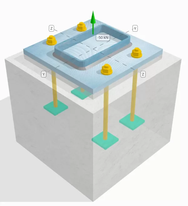
确定设计的列板连接是否足以满足50k的张力负载.
给定数据
柱:
列部分: 250x150x8 rhs
列区域: 5920 毫米2
列材料: AS / NZS 1163 gr. C350
底盘:
基板尺寸: 350 毫米× 350 毫米
基板厚度: 20 毫米
底板材料: AS / NZS 1163 gr. C250
灌浆:
灌浆厚度: 20 毫米
具体:
混凝土尺寸: 450 毫米× 450 毫米
混凝土厚度: 400 毫米
混凝土材料: N28
破裂或无裂缝: 破裂
锚:
锚直径: 16 毫米
有效嵌入长度: 250.0 毫米
嵌入式板宽: 70 毫米
嵌入式板厚度: 10 毫米
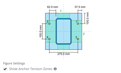
锚偏移距离列的距离: 62.5 毫米
焊缝:
焊接类型: 鱼片
焊接类别: SP
填充金属分类: E43xx
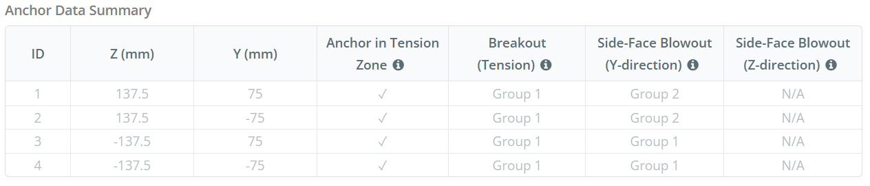
锚数据 (从 SkyCiv计算器):
SkyCiv 免费工具中的模型
立即使用我们的免费在线工具对上面的底板设计进行建模! 无需注册.
定义
负载路径:
当底板受到抬高时 (拉伸) 军队, 这些力被转移到锚杆上, 这反过. 弯曲动作可以看到为 悬臂弯曲 发生在列的法兰或网络周围, 取决于锚定位的位置.
在里面 SkyCiv 底板设计软件, 只有位于 锚张带 被认为有效抵抗提升. 该区域通常包括列法兰或网络附近的区域. 用于矩形柱, 锚点张力区是指与柱墙相邻的区域. 该区域以外的锚点不会导致抗拉力抵抗力,并且被排除在隆起计算之外.
确定基本板的有效区域,以抵抗弯曲, 一个 45-学位分散 从每个锚杆的中心线朝向圆柱面假设. 这个分散定义了 有效的焊接长度 并帮助建立 有效的弯曲宽度 盘子的.
该假设通过近似抬高力如何通过板来简化基板分析.
锚群:
的 SkyCiv 底板设计软件 包括一个直观的功能,该功能标识哪些锚定为评估的锚点组的一部分 混凝土突破 和 混凝土侧面井喷 失败.
一个 锚群 由具有相似有效嵌入深度和间距的多个锚组成, 并且足够近,以至于他们 预计电阻区重叠. 当锚分组时, 它们的能力合并以抵抗施加到该组的总张力.
不符合分组标准的锚被视为 单锚. 在这种情况下, 仅检查单个锚点上的张力力与其自身的有效阻力区域检查.
撬增加因子:
的 SkyCiv 底板设计软件 包括一个应用的选项 撬增加因子 考虑到锚撬动的锚点上的额外拉伸力. 该因素增加了锚检查期间锚的负载需求, 在适用的情况下提供更保守和现实的评估. 默认, 撬动增加因子设置为 1.0, 这意味着除非用户指定,否.
分步计算:
检查一下 #1: 计算焊接容量
开始, 我们需要计算每个锚的负载和每个锚的有效焊接长度. 有效焊接长度由45°分散的最短长度确定, 受实际焊接长度和锚固间距的约束.
为此计算, 锚被归类为 结束锚 要么 中间锚. 最终锚位于行的末端或锚列的末端, 中间锚位于它们之间. 每种计算方法都不同,并取决于列的几何形状. 在这个例子中, 网上有两个锚, 两者都被归类为最终锚.
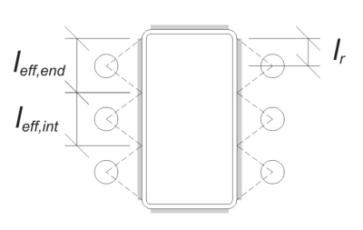
最终锚, 有效的焊接长度受锚式中心线到柱角半径的可用距离的限制. 45°色散不得延伸到这个边界之外.
\(
l_r = frac{d_{上校} – 2t_{上校} – 2r_{上校} – s_ (n_{一个,\文本{边}} – 1)}{2} = frac{250 \, \文本{毫米} – 2 \次 8 \, \文本{毫米} – 2 \次 12 \, \文本{毫米} – 150 \, \文本{毫米} \次 (2 – 1)}{2} = 30 \, \文本{毫米}
\)
内侧, 有效长度受锚间距的一半限制. 端锚的总有效焊接长度是外部和内部长度的总和.
\(
由使用公式计算的最小值控制{效果,结束} = min left( 做, 0.5 s_y 右) + \最小左( 做, l_r 右)
\)
\(
由使用公式计算的最小值控制{效果,结束} = min left( 62.5 \, \文本{毫米}, 0.5 \次 150 \, \文本{毫米} \对) + \最小左( 62.5 \, \文本{毫米}, 30 \, \文本{毫米} \对) = 92.5 \, \文本{毫米}
\)
对于这个例子, 网络锚的最终有效焊接长度被视为端锚的有效长度.
\(
由使用公式计算的最小值控制{效果} = l_{效果,结束} = 92.5 \, \文本{毫米}
\)
下一个, 让我们计算每个锚的负载. 给定的四组 (4) 锚点, 每个锚的负载是:
\(
T_{ü,锚} = frac{n_x}{n_{一个,Ť}} = frac{50 \, \文本{千牛}}{4} = 12.5 \, \文本{千牛}
\)
使用计算的有效焊接长度, 现在,我们可以计算作用在焊接上的每单位长度所需的力.
\(
v^*_ w = frac{T_{ü,锚}}{由使用公式计算的最小值控制{效果}} = frac{12.5 \, \文本{千牛}}{92.5 \, \文本{毫米}} = 0.13514 \, \文本{千牛/毫米}
\)
现在, 我们将使用 作为 4100:2020 条款 9.6.3.10 计算圆角焊缝的设计强度.
\(
\phi v_w = phi 0.6 F_{你的} e_w k_r = 0.8 \次 0.6 \次 430 \, \文本{兆帕} \次 5.657 \, \文本{毫米} \次 1 = 1.1676 \, \文本{千牛/毫米}
\)
除了检查焊接, 我们还需要验证 碱金属的抗性 反对施加的张力,以确保其不控制故障模式.
\(
\phi v_{WBM} = phi 左( \最小左( F_{和 _COL} t_{上校}, F_{和 _bp} t_{BP} \对) \对)
\)
\(
\phi v_{WBM} = 0.9 \时代左( \最小左( 350 \, \文本{兆帕} \次 8 \, \文本{毫米}, 250 \, \文本{兆帕} \次 20 \, \文本{毫米} \对) \对) = 2.52 \, \文本{千牛/毫米}
\)
在这种情况下, 焊接阻力控制在碱金属电阻上.
以来 0.13514 千牛/毫米 < 1.1676 千牛/毫米, 焊接容量是 充足的.
检查一下 #2: 计算由于张力负载而导致的基本板弯曲屈服能力
使用 每个锚负载 以及从锚的中心到柱面的偏移距离 (充当负载偏心), 应用于基板的力矩可以使用 悬臂 假设.
\(
m^* = t_{ü,锚} e = 12.5 \, \文本{千牛} \次 62.5 \, \文本{毫米} = 781.25 \, \文本{千牛} \CDOT text{毫米}
\)
下一个, 使用计算 有效的焊接长度 从上一张检查作为弯曲宽度, 我们可以计算 是一个设计模块,用于根据上部结构载荷设计扩展基础 使用底板的 AISC 360-22, 方程 2-1:
\(
\phi M_s = phi Z_{效果} F_{和 _bp} = 0.9 \次 9250 \, \文本{毫米}^3 次 250 \, \文本{兆帕} = 2081.2 \, \文本{千牛} \CDOT text{毫米}
\)
在哪里,
\(
z_{效果} = frac{由使用公式计算的最小值控制{效果} (t_{BP})^ 2}{4} = frac{92.5 \, \文本{毫米} \次 (20 \, \文本{毫米})^ 2}{4} = 9250 \, \文本{毫米}^ 3
\)
以来 781.25 kn-mm < 2081.2 kn-mm, 基板弯曲屈服能力为 充足的.
检查一下 #3: 计算锚杆拉伸能力
评估 锚杆的拉伸能力, 我们指的是 作为 5216:2021 条款 6.2.2 和 作为 4100:2020 条款 9.2.2.2.
第一, 我们确定 检查锚容量 杆的螺纹部分, 下列的 作为 4100:2020 条款 7.2 和 AS 1275–1985条款 1.7.
\(
A_n = frac{\pi}{4} \剩下( \压裂{D_A}{\文本{毫米}} – 0.9382 P 右)^ 2 \, \文本{毫米}^2 = frac{\pi}{4} \时代左( \压裂{16 \, \文本{毫米}}{1 \, \文本{毫米}} – 0.9382 \次 2 \对)^2 times 1 \, \文本{毫米}可以假设为 156.67 \, \文本{毫米}^ 2
\)
使用 作为 4100:2020 条款 9.2.2, 我们计算 标称张力能力 基于拉伸应力区域和材料强度的螺栓.
\(
N_{tf} = a_n f_{u _anc} = 156.67 \, \文本{毫米}^2 times 800 \, \文本{兆帕} = 125.33 \, \文本{千牛}
\)
然后,我们应用适当的电阻因子来获得 张力的设计锚点.
\(
\φN_{检查锚容量,s} = phi N_{tf} = 0.8 \次 125.33 \, \文本{千牛} = 100.27 \, \文本{千牛}
\)
回想先前计算的 每个锚的张力负载, 并应用 撬增加因子 如果指定.
\(
N^* = p 左( \压裂{n_x}{n_{一个,Ť}} \对) = 1 \时代左( \压裂{50 \, \文本{千牛}}{4} \对) = 12.5 \, \文本{千牛}
\)
以来 12.5 千牛 < 100.27 千牛, 的 锚杆拉伸能力足够.
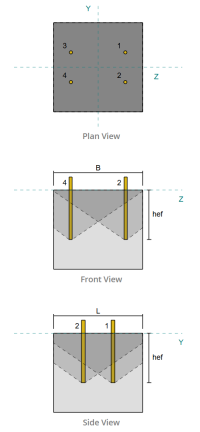
检查一下 #4: 计算张力的混凝土突破能力
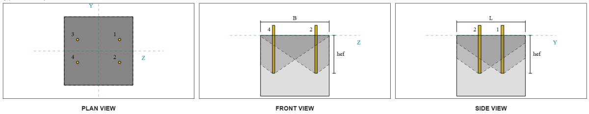
在计算突破能力之前, 我们必须首先确定成员是否有资格 狭窄的成员. 根据 作为 5216:2021 条款 6.2.3.8, 该成员符合狭窄成员的标准. 因此, 一个 修改的 有效嵌入长度 必须用于分解能力计算. 这种调整也影响 特征间距 和 特征边缘距离, 必须相应修改.
根据狭窄的成员标准, 的 修改值 对于锚组如下:
- 修改的有效嵌入长度, \(h__{ef} = 100 \, \文本{毫米}\)
- 修改的特征间距, \(s{铬} = 300 \, \文本{毫米}\)
- 修改的特征边缘距离, \(c’_{铬} = 150 \, \文本{毫米}\)
使用 作为 5216: 2021 条款 6.2.3.3, 我们计算 参考投影混凝土锥体区域 对于单个锚点.
\(
A0_{C,ñ} = 左( s{铬,G1} \对)^2 = 左( 300 \, \文本{毫米} \对)可以假设为 90000 \, \文本{毫米}^ 2
\)
相似地, 我们计算 实际投影混凝土锥体 锚群.
\(
一个_{数控} = l_{数控} b_{数控} = 450 \, \文本{毫米} \次 450 \, \文本{毫米} = 202500 \, \文本{毫米}^ 2
\)
在哪里,
\(
L_{数控} = min left( C_{剩下,G1}, c’_{铬,G1} + r_{嵌入 _ plate} \对) + \最小左( s_{和,与,G1}, s{铬,G1} \cdot 左( n_{与,G1} – 1 \对) \对) + \最小左( C_{对,G1}, c’_{铬,G1} + r_{嵌入 _ plate} \对)
\)
\(
L_{数控} = min left( 87.5 \, \文本{毫米}, 150 \, \文本{毫米} + 18 \, \文本{毫米} \对) + \最小左( 275 \, \文本{毫米}, 300 \, \文本{毫米} \点 (2 – 1) \对) + \最小左( 87.5 \, \文本{毫米}, 150 \, \文本{毫米} + 18 \, \文本{毫米} \对)
\)
\(
L_{数控} = 450 \, \文本{毫米}
\)
\(
b_{数控} = min left( C_{最佳,G1}, c’_{铬,G1} + r_{嵌入 _ plate} \对) + \最小左( s_{和,和,G1}, s{铬,G1} \cdot 左( n_{和,G1} – 1 \对) \对) + \最小左( C_{底部,G1}, c’_{铬,G1} + r_{嵌入 _ plate} \对)
\)
\(
b_{数控} =分钟左( 150 \, \文本{毫米}, 150 \, \文本{毫米} + 18 \, \文本{毫米} \对) + \最小左( 150 \, \文本{毫米}, 300 \, \文本{毫米} \点 (2 – 1) \对) + \最小左( 150 \, \文本{毫米}, 150 \, \文本{毫米} + 18 \, \文本{毫米} \对)
\)
\(
b_{数控} = 450 \, \文本{毫米}
\)
的 嵌入式板有效半径 用于为混凝土突破提供额外的能力. 确定这一点, 将嵌入板的厚度加到锚直径的一半.
下一个, 我们评估 特征强度 使用一个锚 作为 5216:2021 情商. 6.2.3.2
\(
n0_{检查锚容量,C} = k_1 开方{\压裂{f'_c}{\文本{兆帕}}} \剩下( \压裂{h__{ef,G1}}{\文本{毫米}} \对)^{1.5} \, \文本{ñ}
\)
\(
n0_{检查锚容量,C} = 8.9 \次 sqrt{\压裂{28 \, \文本{兆帕}}{1 \, \文本{兆帕}}} \时代左( \压裂{100 \, \文本{毫米}}{1 \, \文本{毫米}} \对)^{1.5} \次 0.001 \, \文本{千牛} = 47.094 \, \文本{千牛}
\)
在哪里,
- \(钢底板设计欧洲规范{1} = 8.9\) 用于预制锚栓
现在, 我们通过计算必要的 参数 对于突破性阻力.
锚固组的最短边缘距离确定为:
\(
C_{分,ñ} = min left( C_{剩下,G1}, C_{对,G1}, C_{最佳,G1}, C_{底部,G1} \对) = min left( 87.5 \, \文本{毫米}, 87.5 \, \文本{毫米}, 150 \, \文本{毫米}, 150 \, \文本{毫米} \对) = 87.5 \, \文本{毫米}
\)
根据 作为 5216:2021 情商. 6.2.3.4, 参数的值核算混凝土中应力分布的值为:
\(
\psi_{s,ñ} = min left( 0.7 + 0.3 \剩下( \压裂{C_{分,ñ}}{c’_{铬,G1}} \对), 1.0 \对) = min left( 0.7 + 0.3 \时代左( \压裂{87.5 \, \文本{毫米}}{150 \, \文本{毫米}} \对), 1 \对) = 0.875
\)
的 壳剥落效果 用于使用 作为 5216:2021 方程 6.2.3.5, 给予:
\(
\psi_{检查锚容量,ñ} = min left( 0.5 + \压裂{h__{ef,G1}}{\文本{毫米} \点 200}, 1.0 \对) = min left( 0.5 + \压裂{100 \, \文本{毫米}}{1 \, \文本{毫米} \点 200}, 1 \对) = 1
\)
此外, 两者 偏心率因子 和 压缩影响因子 被视为:
\(
\psi_{欧共体,ñ} = 1
\)
\(
\psi_{m,ñ} = 1
\)
然后,我们结合了所有这些因素,并应用 作为 5216:2021 方程 6.2.3.1 评估 设计混凝土锥体突破性阻力 对于锚点:
\(
\φN_{检查锚容量,C} [object Window]{检查锚容量} n0_{检查锚容量,C} \剩下( \压裂{一个_{数控}}{A0_{C,ñ}} \对) \psi_{s,ñ} \psi_{检查锚容量,ñ} \psi_{欧共体,ñ} \psi_{m,ñ}
\)
\(
\φN_{检查锚容量,C} = 0.6667 \次 47.094 \, \文本{千牛} \时代左( \压裂{202500 \, \文本{毫米}^ 2}{90000 \, \文本{毫米}^ 2} \对) \次 0.875 \次 1 \次 1 \次 1 = 61.814 \, \文本{千牛}
\)
的 总施加负荷 在锚点上,通过将每个锚的张力负载乘以锚数来计算, 随着撬动的增加因子而根据需要:
\(
N^* = p 左( \压裂{n_x}{n_{一个,Ť}} \对) n_{一个,G1} = 1 \时代左( \压裂{50 \, \文本{千牛}}{4} \对) \次 4 = 50 \, \文本{千牛}
\)
以来 50 千牛 < 61.814 千牛 具体的突破能力是 充足的.
检查一下 #5: 计算锚推拉力
的 拔出能力 锚点的嵌入端受阻力支配. 第一, 我们计算有效拉出电阻有效的最大锚头维, 按照 作为 5216:2021 条款 6.3.4.
\(
d_{H,\文本{最高}} = min left( b_{嵌入 _ plate}, 6 \剩下( t_{嵌入 _ plate} \对) + d_a 对) = min left( 70 \, \文本{毫米}, 6 \次 (10 \, \文本{毫米}) + 16 \, \文本{毫米} \对) = 70 \, \文本{毫米}
\)
下一个, 我们使用矩形嵌入板的净轴承面积:
\(
A_h = 左( d_{H,\文本{最高}}^2 对) – 一个_{杆} = 左( (70 \, \文本{毫米})^2 对) – 201.06 \, \文本{毫米}可以假设为 4698.9 \, \文本{毫米}^ 2
\)
在哪里,
\(
一个_{杆} = frac{\pi}{4} (D_A)^2 = frac{\pi}{4} \次 (16 \, \文本{毫米})可以假设为 201.06 \, \文本{毫米}^ 2
\)
然后我们计算 设计基本的锚拔出强度 使用 作为 5216:2021 条款 6.3.4:
\(
N_{检查锚容量,p} [object Window]{检查锚容量} k_2 A_h 左( f’_c 对) = 0.6667 \次 7.5 \次 4698.9 \, \文本{毫米}^2 times (28 \, \文本{兆帕}) = 657.88 \, \文本{千牛}
\)
回想先前计算的 每个锚的张力负载:
\(
N^* = p 左( \压裂{n_x}{n_{一个,Ť}} \对) = 1 \时代左( \压裂{50 \, \文本{千牛}}{4} \对) = 12.5 \, \文本{千牛}
\)
以来 12.5 千牛 < 657.88 千牛, 锚推拔出能力是 充足的.
检查一下 #6: 计算Y方向的侧面井喷容量
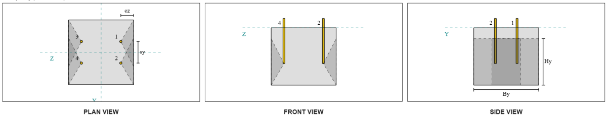
让我们考虑一下侧面井喷锚群 1 对于容量计算. 指锚数据摘要, 锚点ID 3 和 4 是SFY组的一部分 1.
我们首先计算到边缘距离到达 故障边缘.
\(
C_{与,\文本{分}} = min left( C_{\文本{剩下},G1}, C_{\文本{对},G1} \对) = min left( 87.5 \, \文本{毫米}, 362.5 \, \文本{毫米} \对) = 87.5 \, \文本{毫米}
\)
下一个, 我们确定边缘距离到 正交边缘.
\(
C_{和,\文本{分}} = min left( C_{\文本{最佳},G1}, C_{\文本{底部},G1} \对) = min left( 150 \, \文本{毫米}, 150 \, \文本{毫米} \对) = 150 \, \文本{毫米}
\)
使用 作为 5216:2021 条款 6.2.7.3, 让我们计算 参考投影区域 一个紧固件.
\(
A0_{C,NB} = 左( 4 C_{与,\文本{分}} \对)^2 = 左( 4 \次 87.5 \, \文本{毫米} \对)可以假设为 122500 \, \文本{毫米}^ 2
\)
由于我们正在检查锚群的容量, 让我们得到 实际投影区域 使用锚群使用 作为 5216:2021 条款 6.2.7.2.
\(
一个_{数控} = b_{C,NB} H_{C,NB} = 450 \, \文本{毫米} \次 325 \, \文本{毫米} = 146250 \, \文本{毫米}^ 2
\)
在哪里,
\(
b_{C,NB} = min left( 2 C_{与,\文本{分}}, C_{\文本{最佳},G1} \对) + s_{\文本{和},和,G1} + \最小左( 2 C_{与,\文本{分}}, C_{\文本{底部},G1} \对)
\)
\(
b_{C,NB} = min left( 2 \次 87.5 \, \文本{毫米}, 150 \, \文本{毫米} \对) + 150 \, \文本{毫米} + \最小左( 2 \次 87.5 \, \文本{毫米}, 150 \, \文本{毫米} \对) = 450 \, \文本{毫米}
\)
\(
H_{C,NB} = 2 C_{与,\文本{分}} + \剩下( \最小左( t_{\文本{浓}} – H_{\文本{ef}}, 2 C_{与,\文本{分}} \对) \对)
\)
\(
H_{C,NB} = 2 \次 87.5 \, \文本{毫米} + \剩下( \最小左( 400 \, \文本{毫米} – 250 \, \文本{毫米}, 2 \次 87.5 \, \文本{毫米} \对) \对) = 325 \, \文本{毫米}
\)
在计算 特征具体的爆破强度 个体锚的, 我们将使用 作为 5216:2021 条款 6.2.7.2.
\(
n0_{检查锚容量,CB} = k_5 左( \压裂{C_{与,\文本{分}}}{\文本{毫米}} \对) \sqrt{\压裂{啊}{\文本{毫米}^ 2}} \sqrt{\压裂{f'_c}{\文本{兆帕}}} \, ñ
\)
\(
n0_{检查锚容量,CB} = 8.7 \时代左( \压裂{87.5 \, \文本{毫米}}{1 \, \文本{毫米}} \对) \次 sqrt{\压裂{4698.9 \, \文本{毫米}^ 2}{1 \, \文本{毫米}^ 2}} \次 sqrt{\压裂{28 \, \文本{兆帕}}{1 \, \文本{兆帕}}} \次 0.001 \, \文本{千牛}
\)
\(
n0_{检查锚容量,CB} = 276.13 \, \文本{千牛}
\)
在哪里,
- \(钢底板设计欧洲规范{5} = 8.7\) 用于开裂混凝土
- \(钢底板设计欧洲规范{5} = 12.2\) 用于无裂缝的混凝土
然后, 我们会得到 侧面井喷参数.
可以根据混凝土中应力分布的干扰的参数可以根据 作为 5216:2021 条款 6.2.7.4.
\(
\psi_{s,NB} = min left( 0.7 + 0.3 \剩下( \压裂{C_{和,\文本{分}}}{2 C_{与,\文本{分}}} \对), 1.0 \对)
\)
\(
\psi_{s,NB} = min left( 0.7 + 0.3 \时代左( \压裂{150 \, \文本{毫米}}{2 \次 87.5 \, \文本{毫米}} \对), 1 \对) = 0.95714
\)
来自 作为 5216:2021 条款 6.2.7.5 然后使用来获取参数会计 小组效应.
\(
\psi_{G,NB} = max left( \sqrt{n_{和,G1}} + \剩下( 1 – \sqrt{n_{和,G1}} \对) \剩下( \压裂{\最小左( s_{和,G1}, 4 C_{与,\文本{分}} \对)}{4 C_{与,\文本{分}}} \对), 1.0 \对)
\)
\(
\psi_{G,NB} = max left( \sqrt{2} + \剩下( 1 – \sqrt{2} \对) \时代左( \压裂{\最小左( 150 \, \文本{毫米}, 4 \次 87.5 \, \文本{毫米} \对)}{4 \次 87.5 \, \文本{毫米}} \对), 1 \对)
\)
\(
\psi_{G,NB} = 1.2367
\)
最后, 参考 作为 5216:2021 情商. 6.2.7 用于头锚杆, 的 设计具体的爆破抵抗 是:
\(
\φN_{检查锚容量,CB} = phi_m n0_{检查锚容量,CB} \剩下( \压裂{一个_{数控}}{A0_{C,NB}} \对) \psi_{s,NB} \psi_{G,NB} \psi_{欧共体,ñ}
\)
\(
\φN_{检查锚容量,CB} = 0.6667 \次 276.13 \, \文本{千牛} \时代左( \压裂{146250 \, \文本{毫米}^ 2}{122500 \, \文本{毫米}^ 2} \对) \次 0.95714 \次 1.2367 \次 1 = 260.16 \, \文本{千牛}
\)
对于这个锚点, 只有两个 (2) 锚属于组. 因此, 的 设计张力力 对于锚点是:
\(
N^* = p 左( \压裂{n_x}{n_{一个,Ť}} \对) n_{和,G1}
\)
\(
n^* = 1 \时代左( \压裂{50 \, \文本{千牛}}{4} \对) \次 2 = 25 \, \文本{千牛}
\)
以来 25 千牛 < 260.16 千牛, 沿y方向的混凝土侧面井喷为 充足的.
侧面井喷锚群 2 也可以使用并产生相同的结果, 由于设计是对称的.
检查一下 #7: 计算Z方向的侧面井喷容量
该计算不适用于沿z方向的故障, 随着边缘到侧的距离超过有效嵌入长度的一半.
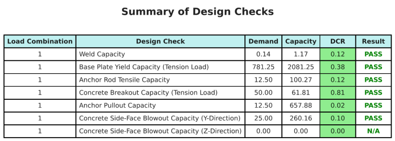
设计概要
的 SkyCiv底板设计软件 可以自动为此设计示例生成逐步计算报告. 它还提供了执行的检查及其结果比率的摘要, 一目了然地使信息易于理解. 以下是示例摘要表, 报告中包括.
SkyCiv样本报告
查看 SkyCiv 底板设计报告的详细程度和清晰度. 该报告包括所有关键的设计检查, 方程式, 并以清晰易读的格式呈现结果. 完全符合设计标准. 单击下面查看使用 SkyCiv 底板计算器生成的示例报告.
购买基板软件
单独购买基本板设计模块的完整版本,而没有任何其他SkyCiv模块. 这为您提供了底板设计的完整结果, 包括详细报告和更多功能.