Qu'est-ce qu'une charge excentrique?
Une charge excentrique est toute charge qui est non appliqué au centre de gravité du membre. En analyse par éléments finis, charges ponctuelles, charges réparties, et d'autres forces sont généralement appliquées au centre de gravité de la section (e.g. le centre géométrique de la section). Par contre, dans certains scénarios, vous souhaiterez peut-être appliquer une force décentrée – par exemple, appliquer une charge à la semelle d'une poutre en I, plutôt que le web. En supposant qu'il s'agisse d'une charge latérale, cela créera une force de torsion et un comportement de chargement globalement différent dans l'élément.
Comment appliquer des charges excentriques à un modèle
Ici, nous allons vous présenter un exemple de la façon dont vous pouvez utiliser Liens rigides appliquer une telle charge excentrique. En utilisant des liens rigides, nous pouvons transférer la charge du centre de gravité de la barre vers un emplacement différent. Liens rigides sont extrêmement utiles pour ce genre de travail, car il calcule automatiquement le moment résultant et les autres forces d'un endroit à un autre.
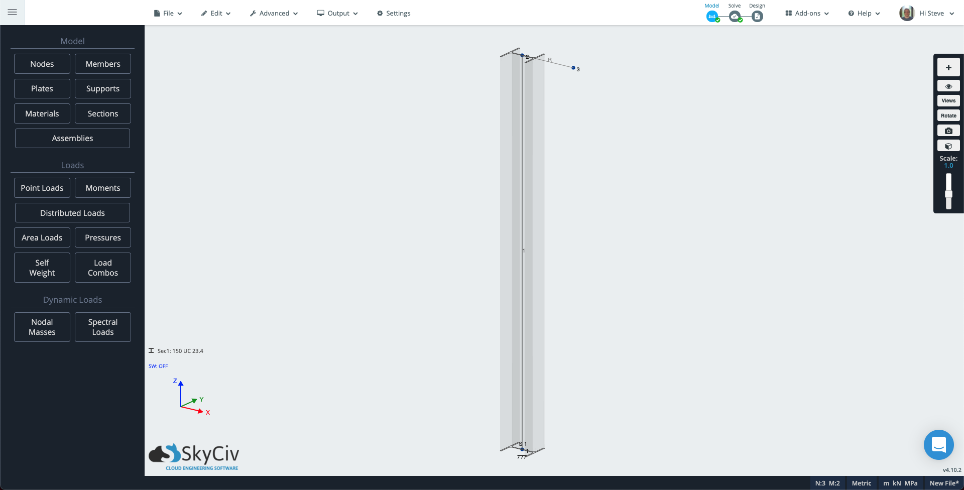
Rendez-vous sur S3D et créer un nouveau modèle. Prochain, sélectionnez l'outil Plume dans le panneau de droite ou en appuyant sur V. Cliquez une fois pour placer le premier nœud à l'origine, puis tirez vers le haut d'environ 2 m (6.5pi) créer une colonne.
Dans le coin près du système de coordonnées, Cliquez sur Sec1: Non défini, puis dans le panneau de gauche, Cliquez sur Constructeur pour ouvrir le générateur de sections. Choisissez une section de colonne, pour cette note technique j'ai sélectionné un 150UC23.4 australien, c'est environ un 6×6 I section pour nos amis impériaux. Dans le panneau de gauche, cliquez sur les supports et ajoutez un support fixe sur Node 1.
Nous allons maintenant ajouter un autre élément afin de pouvoir créer une charge excentrique qui induit une torsion et une autre qui crée un effet de flambage sur notre poteau..
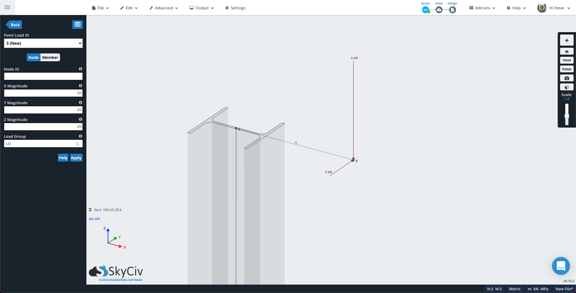
Pour voir l'orientation de votre colonne, cliquez sur l'icône de visibilité dans le panneau de droite et sélectionnez 3Membres D. Utilisez l'outil Plume pour dessiner un 300 mm (1pi) barre dans la direction X à partir du haut de la colonne. Si “3Membre D” est allumé, vous verrez que ce membre utilise la section colonne. Cliquez sur le nouveau membre, puis dans le panneau de gauche, changez l'attribut type en Rigide et cliquez Appliquer.
Votre modèle devrait ressembler à celui ci-dessous:
Cliquez sur Charges ponctuelles dans le panneau de gauche. Remplissez les attributs avec les valeurs suivantes:
- ID de nœud: 3
- De l'ampleur: -5 (centre de torsion, ajoutez plutôt cette valeur à la magnitude Y).
- Groupe de charge: Charge de flambage
Cliquez sur Appliquer et la charge ponctuelle sera ajoutée au modèle. L'ID de charge ponctuelle augmentera jusqu'à 2 (Nouveau) alors ajoutez une autre charge pour créer une torsion dans la colonne:
- ID de nœud: 3
- Et l'ampleur: 2 (centre de torsion, ajoutez plutôt cette valeur à la magnitude Z).
- Groupe de charge: Charge de torsion
Nœud 3 centre de torsion.
centre de torsion, puis ouvrez le mode de rendu – centre de torsion. Remplacez la liste déroulante dans le panneau de gauche par Charge de flambage, l'échelle de déviation à Auto, et le menu déroulant Résultats des membres pour Affichage des résultats de l'analyse de vos plaques. Vous pouvez maintenant voir comment la première charge excentrique provoque un effet de flambement.
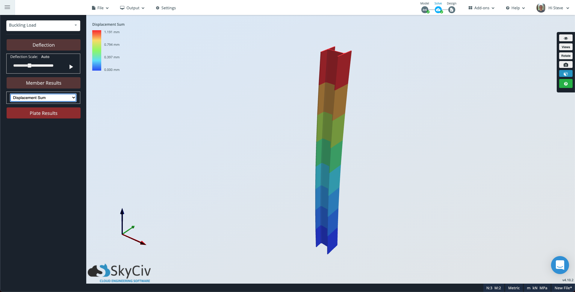
Notez que si vous souhaitez voir une subdivision plus fine du membre, vous pouvez accéder à Paramètres Faire glisser de gauche à droite sélectionnera tout ce que la zone de sélection touche Solveur, changer la Points d'évaluation par membre à un nombre approprié et exécutez à nouveau la résolution.
Maintenant, changez la liste déroulante de Charge de flambage à Charge de torsion et la Résultats des membres à Contrainte de torsion. Dans le cas présent, le membre apparaîtra en gris car la charge de torsion est constante dans tout le membre.
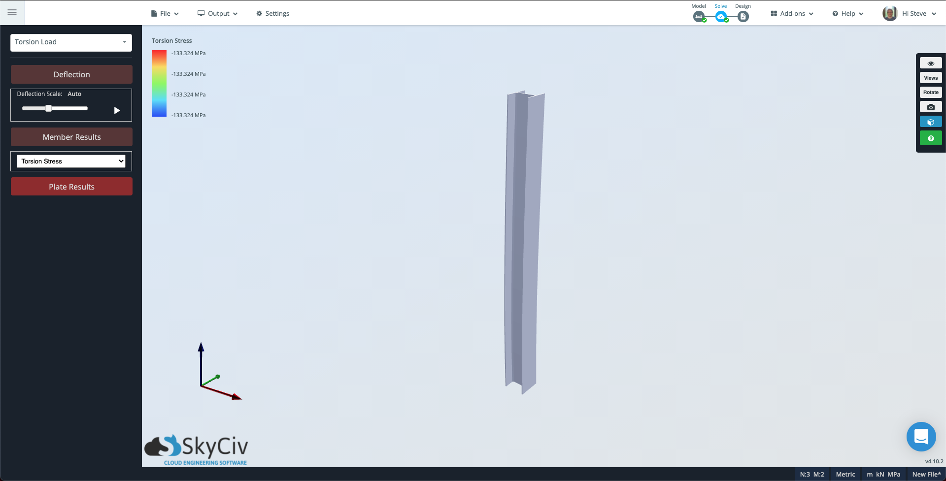
Notez que l'échelle de contour en haut à gauche indique toujours l'ampleur de la torsion que subit le poteau..