
Qu'est-ce qu'une connexion de cisaillement?
Une connexion de cisaillement est un joint qui transfère la force de cisaillement entre deux éléments sans transférer de moment significatif.. Si une poutre porte des les efforts tranchants, cette force passe à travers la connexion dans la colonne de support comme force axiale. Les connexions de cisaillement se comportent comme une goupille (FFFFFR dans SkyCiv Structurel 3D), contrairement à connexions moment, qui maintiennent la rotation finale.
Dans l'AISC 360-16 termes, c'est un Facile lien (B3.4): il est supposé tourner librement et supporter un moment négligeable. AS 4100:2020 appelle l'arrangement équivalent construction simple. Un joint semi-rigide est un troisième cas, avec rigidité en rotation réelle mais partielle, et il doit être modélisé de cette façon plutôt que traité comme simple.
Une plaque ou un angle transporte la force entre les deux éléments. Dans l'exemple ci-dessus, toute charge vers le bas sur la poutre passe dans l'élément de support à travers l'angle. Parce que rien ne retient les ailes des poutres, l'articulation peut tourner, c'est ce qui en fait une connexion par cisaillement plutôt qu'une connexion par moment.
Connexions de cisaillement sont les connexions les plus courantes dans les charpentes en acier. Où un cadre est contreventé, le contreventement assure la stabilité latérale, donc les connexions momentanées ne sont nécessaires que lorsque le cadre repose sur l'action du cadre. C'est pourquoi la plupart des concepteurs optent pour une connexion par cisaillement partout où l'analyse le permet.: ils sont plus simples à fabriquer et moins chers à monter.
Shear connection design comes down to following the beam reaction from the beam web, through the bolts, plate or angle and welds, into the support, and checking every part it passes through. This page sets out that procedure with the AISC 360-16 équations, and links to five fully worked AISC calc sheet examples that apply it to real connections.
SkyCiv Connection Design vérifie les connexions de cisaillement à AISC 360-16 dans les TSA et les LRFD, et à AS 4100:2020.
Types de connexions de cisaillement
Les connexions de cisaillement portent le nom du composant qui supporte la charge et de l'endroit où il se trouve.. Les options disponibles dépendent du code de conception et de la composition des poutres., donc les listes ci-dessous sont divisées de cette façon.
Poutre vers poteau en I, ou poutre à poutre (AISC 360-16)
Six configurations, chaque charpente disponible à la semelle du poteau, à la colonne web, ou poutre à poutre à travers la bande:
- Angle unique. Un support en forme de L entre l'âme de la poutre et le support. L'option la plus légère, et le plus flexible, donc il convient aux charges légères. The reaction sits off the support-side bolt line, so those bolts carry an eccentricity (worked example).
- Angle double. Angles sur les deux faces de l'âme de la poutre. The extra angle puts the beam-side bolts in double shear and makes the connection more forgiving during erection, c'est pourquoi c'est la bête de somme pour les poutres plus lourdes (worked example).
- Plaque simple. La languette de cisaillement. Une assiette, soudé en atelier au support et boulonné à l'âme de la poutre. Généralement le moins cher du groupe, car il y a une ligne de soudure et un groupe de boulons (worked example). When the plate has to reach past the column flanges into a column web, it becomes an extended single plate, which is designed differently (worked example).
- Plaque double. Plaques sur les deux faces de la bande, utilisé là où une seule plaque ne peut pas supporter la cisaille ou s'adapter au groupe de boulons requis.
- Plaque d'extrémité. Une plaque soudée en extrémité de poutre et boulonnée au support. Il faut que la poutre soit coupée à longueur avec précision, puisque la plaque ne laisse aucun réglage (worked example).
- Web directement soudé. L'âme de la poutre soudée directement au support, sans plaque intermédiaire ni angle. Il n'y a pas de boulons à vérifier, mais il nécessite un soudage sur site et abandonne la tolérance de montage fournie par un détail boulonné..
Poutre vers colonne HSS (AISC 360-16)
Le cadrage dans une section creuse change ce qui convient, car il n'y a pas de bride sur laquelle boulonner et pas d'accès au côté éloigné pour une clé. Cinq configurations sont disponibles:
- Angle unique et Angle double
- Plaque simple
- Seul WT. Un té découpé dans une large bride, sa tige soudée ou boulonnée à l'âme de la poutre et sa semelle à la face du poteau.
- Angle d'assise. Une cornière sous la semelle inférieure portant la poutre en appui, normalement avec un clip supérieur pour la stabilité. Contrairement aux types connectés au Web, celui-ci fonctionne sur la bride.
AS 4100:2020
Le code australien couvre les charpentes poutre-colonne en I et poutre-poutre., avec quatre configurations:
- Plaque latérale Web, l'AS 4100 nom de la languette de cisaillement.
- Plaque d'extrémité flexible
- Angle unique et Angle double
AS 4100 la couverture est uniquement en cisaillement, et ne s'étend pas aux colonnes HSS, les profilés en "C", contreventement ou épissures. Ce sont des AISC 360-16.
How to design a shear connection to AISC 360-16
Every shear connection is designed the same way: take the factored beam end reaction, [mathin] R_{u} [mathin] (ou [mathin] R_{a} [mathin] for ASD), and check each part of the load path against it. The reaction leaves the beam web, passes through the beam-side bolts or welds into the plate or angles, and then through the support-side bolts or welds into the column or girder. A failure anywhere along that path is a failure of the connection.
The equations below are the LRFD forms from AISC 360-16 et le manuel AISC 15e édition. Pour les TSA, replace [mathin] \phi R_{n} [mathin] avec [mathin] R_{n} / \Omega [mathin], en utilisant le [mathin] \Omega [mathin] given in the same clause ([mathin] \Omega = 2.00 [mathin] où [mathin] \phi = 0.75 [mathin], et [mathin] \Omega = 1.50 [mathin] où [mathin] \phi = 1.00 [mathin]).
1. Detailing limits (J3.3, J3.4)
Avant tout contrôle de solidité, the geometry has to be buildable and match the assumptions behind the strength equations. Bolts need a minimum spacing and edge distance, a wrench needs room to turn, and the plate or angle should be at least half the beam’s T dimension deep so the beam end stays stable. L'espacement minimum des boulons est:
[math] s_{min} = 2\tfrac{2}{3}\, d_{b} \qquad (3\, d_{b}\ \text{preferred}) [math]
Minimum edge distances come from Table J3.4, with an increment from Table J3.5 when the edge is measured across a slotted hole. In the worked examples a detailing limit is often the highest ratio in the whole connection. That is normal: designers lay the bolts out at the limits to keep the plate small.
2. Bolt shear and eccentricity (J3.6, Manual Part 7)
The strength of one bolt in shear is:
[math] \phi r_{v} = \phi\, F_{nv}\, A_{b}\, N_{s} = \phi\, F_{nv}\, \frac{\pi}{4} d_{b}^{2}\, N_{s}, \qquad \phi = 0.75 [math]
où [mathin] F_{nv} [mathin] comes from Table J3.2 (54 ksi for A325-N and 68 ksi for A490-N, grades within ASTM F3125) et [mathin] N_{s} [mathin] is the number of shear planes. The bolts in a double angle beam-side group are in double shear, [mathin] N_{s} = 2 [mathin].
The reaction rarely acts on the bolt line. When it sits a distance e away, the bolts carry a moment [mathin] R_{u}\, e [mathin] as well as the shear, and the group delivers fewer than n bolts’ worth of strength. Le centre de rotation instantané (ICOR) method finds that reduced count, the coefficient C, from the load-deformation curve of each bolt (Manual Eq. 7-1):
[math] R = R_{ult} \left( 1 – e^{-10\Delta} \right)^{0.55} [math]
[math] \phi R_{n} = C\, \phi r_{v} [math]
How much eccentricity to design for depends on the connection type, and this is where the five worked examples differ most:
| Lien | Excentricité de conception | Effect in the worked example |
|---|---|---|
| Plaque unique (conventional) | [mathin] e = a/2 [mathin] from Manual Table 10-9 | 2 in to the bolt line becomes e = 1 in; three bolts give C = 2.71 |
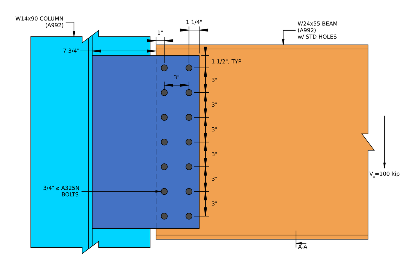
| Extended single plate | Full distance from the weld to the bolt group | e = 10.25 in cuts 14 bolts to 6.29 effective bolts |
| Angle unique, support side | [mathin] e = g + t_{w}/2 [mathin], from the support bolt line to the middle of the beam web | e = 1.85 in cuts 2 bolts to 1.24 boulons’ worth |
| Double angle, beam side | Neglected (Manual Part 10) | The bolt group is treated as concentric |
For the iteration itself, voir calcul du groupe de boulons à l'aide d'ICOR, or run a bolt group in the calculateur de boulons.
3. Roulement de boulon et arrachement (J3.10)
Each bolt pushes on the edge of its hole. The ply either crushes locally around the hole (palier) or tears a strip out to the next hole or the edge (arrachement). With deformation at service load a design consideration:
[math] \phi r_{n} = \phi\, \min\left( 1.2\, l_{c}\, t\, F_{u},\ 2.4\, d_{b}\, t\, F_{u} \right), \qquad \phi = 0.75 [math]
[math] l_{c1} = L_{e} – \frac{d_{h}}{2} \qquad l_{c2} = s – d_{h} [math]
The edge bolt has the short clear distance [mathin] l_{c1} [mathin], so tear-out usually limits it, while the inner bolts reach the 2.4 d t Fu bearing cap. Check every ply: the plate or angles, and the beam web. A thin beam web is often the weak ply, because the angles or plate are sized independently. In the double angle example the two 1/4 in angles give 0.5 in of steel against the bolts, Voiture de course de côte similaire à celle conçue par John 1/4 in beam web has only one ply, and bearing on the web is the highest strength ratio, à 0.760.
Each bolt then delivers the least of its shear, bearing and tear-out strengths, and the group strength is the sum (J3.6 Commentaire):
[math] \phi R_{n,eff} = \frac{C}{n} \sum_{i=1}^{n} \min\left( \phi r_{v},\ \phi r_{n,plate,i},\ \phi r_{n,web,i} \right) [math]
4. Cisaillement de bloc (J4.3)
A block of the plate, angle or coped beam web can tear out around the bolt group: shear along the line of holes plus tension across to the free edge, usually an L-shaped block.
[math] \phi R_{n} = \phi \left( 0.6\, F_{u} A_{nv} + U_{bs} F_{u} A_{nt} \right) \le \phi \left( 0.6\, F_{y} A_{gv} + U_{bs} F_{u} A_{nt} \right), \qquad \phi = 0.75 [math]
[mathin] U_{bs} = 1 [mathin] when the tension stress is uniform, which is the case for a single line of bolts. The net areas deduct each hole at [mathin] d_{h} + 1/16\,in [mathin] for damage during punching (B4.3). In the shear end plate example, block shear of the plate is the second highest ratio, à 0.920.
5. Shear yielding and shear rupture (J4.2)
The plate or angles carry the whole reaction in shear, across the gross section (qui donne) and across the net section through the holes (rupture):
[math] \phi R_{n} = \phi\, 0.6\, F_{y}\, A_{gv}, \qquad \phi = 1.00 [math]
[math] \phi R_{n} = \phi\, 0.6\, F_{u}\, A_{nv}, \qquad \phi = 0.75 [math]
In the single plate example, shear rupture of the 1/2 in plate is the highest load check, à 0.629.
6. Plate flexure and the shear-flexure interaction
The reaction acts at a distance from the support, so a single plate is a short cantilever. SkyCiv checks it with the Manual’s double-coped beam procedure, which treats the plate like a beam web coped top and bottom, and checks flexural rupture on the net section through the holes. Because the same section carries shear and moment, the two combine:
[math] \left( \frac{V_{u}}{\phi V_{n}} \right)^{2} + \left( \frac{V_{u}}{\phi R_{n}} \right)^{2} \le 1.0 [math]
This check grows with the eccentricity. In the conventional shear tab it is minor, but in the extended single plate example the rupture interaction governs the connection at 0.938.
7. Ductilité: the maximum plate thickness (Manual Part 10)
A shear connection is assumed to rotate. Si la plaque est plus résistante en flexion que les boulons ne le sont en cisaillement, the bolts break before the plate yields, which is a brittle failure and contradicts the simple connection assumption. The Manual caps the plate thickness so the plate yields first:
[math] M_{max} = \frac{F_{nv}}{0.90}\, \frac{\pi}{4} d_{b}^{2}\, C’ [math]
[math] t_{max} = \frac{6\, M_{max}}{F_{y}\, d_{p}^{2}} [math]
C’ is the bolt group coefficient for moment alone. This is the one check that a thicker plate makes worse. In the single plate example a 1/2 in plate sits at 0.966 of its limit.
8. Weld strength and the base metal limit (J2.4, Manual Part 9)
The fillet welds that join the plate or angles to the support (or the end plate to the beam web) carry the reaction along their length:
[math] \phi R_{n} = \phi\, 0.6\, F_{EXX}\, \frac{\sqrt{2}}{2}\, w\, L_{w} \left( 1 + 0.5\, \sin^{1.5}\theta \right), \qquad \phi = 0.75 [math]
For a vertical reaction on vertical welds, [mathin] \theta = 0 [mathin] and the directional factor is 1.0. The steel either side of the weld also limits how much of the weld size counts. For welds on both faces of a plate of thickness t, the usable size in sixteenths is:
[math] D_{max} = \frac{ \frac{t}{2}\, F_{u} }{3.09\,kip/in} [math]
So a bigger weld does not always help. In the shear end plate example the 0.355 in beam web limits the usable weld to about 0.233 in, and the weld governs the connection at 0.995. For a single plate, the Manual also asks for fillets of [mathin] \frac{5}{8}\, t_{p} [mathin] on both sides, so that the weld can develop the plate if it yields. Try sizes in the calculateur de soudure.
9. The supporting and supported members
The connection is only as good as the steel it attaches to. A coped beam has a reduced section at the cope, which needs its own block shear, shear and flexure checks; the single angle example works these through for a W12x14 coped at the top flange. Where the beam frames into a girder web or a thin column web, check bearing and tear-out on that web too.
Shear connection design examples (AISC 360-16 LRFD)
Each example below is a full AISC calc sheet from SkyCiv Connection Design, written out step by step with every equation, substituted value and DCR. They show how the governing check moves from one connection type to the next.
| Exemple | Members and load | Lien | Governing load check |
|---|---|---|---|
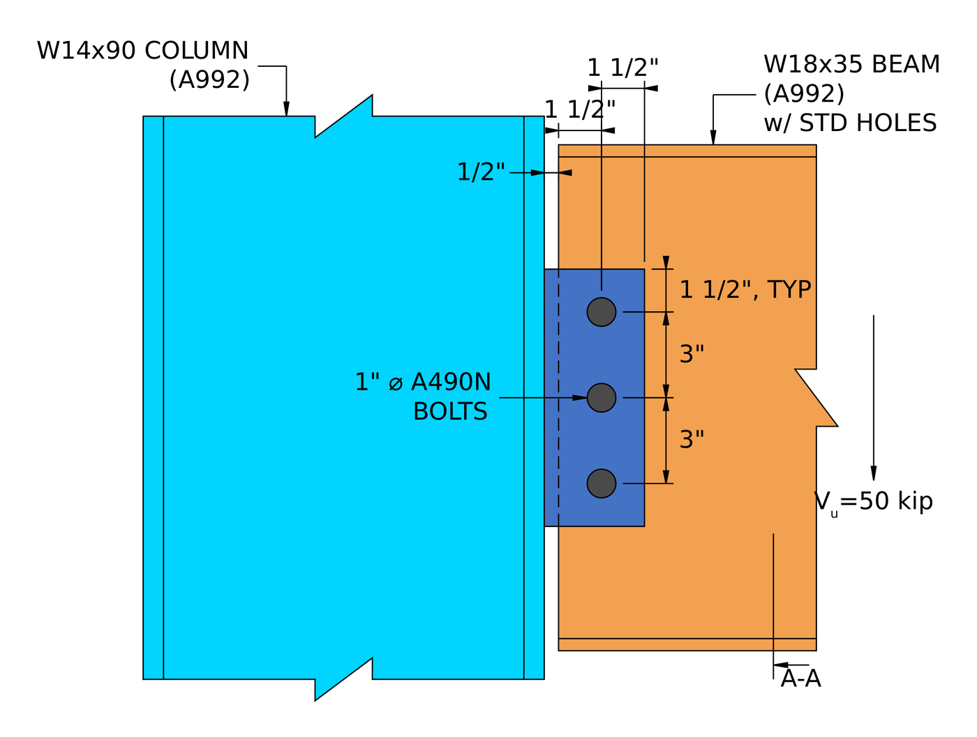
| Plaque unique (languette de cisaillement) | W18x35 beam to W14x90 column flange, 50 kip | 1/2 en assiette, trois 1 in A490-N bolts | Plate shear rupture, 0.629 |
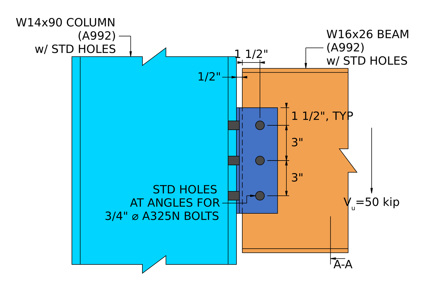
| Double angle | W16x26 beam to W14x90 column flange, 50 kip | 2L4x3-1/2×1/4, three rows of 3/4 in A325-N each side | Bolt bearing on the beam web, 0.760 |
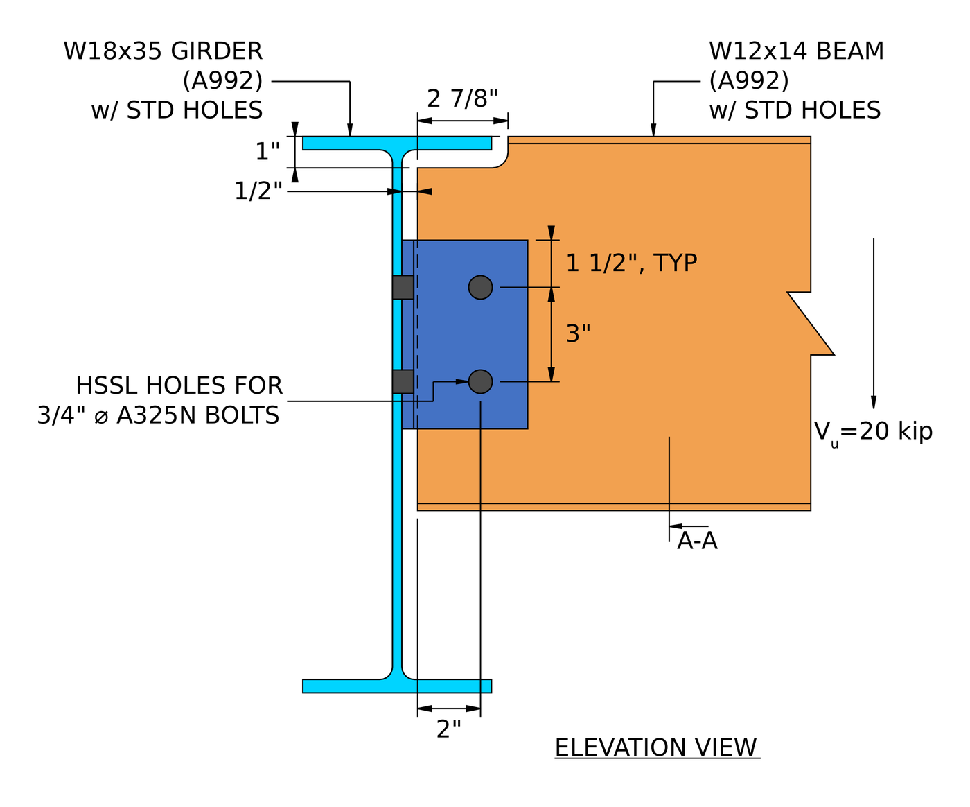
| Angle unique | Coped W12x14 beam to W18x35 girder web, 20 kip | L4x3x3/8, two rows of 3/4 in A325-N each leg | Bolt shear at the girder, 0.901 |
| Extended single plate | W24x55 beam to W14x90 column web, 100 kip | 3/8 X 13 X 21 in A36 plate, fourteen 3/4 in A325-N | Interaction de cisaillement et de flexion (rupture), 0.938 |
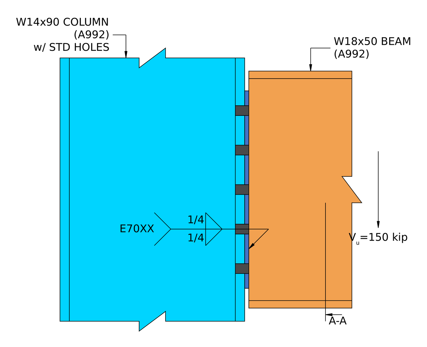
| Shear end plate | W18x50 beam to W14x90 column flange, 150 kip | 5/16 X 8 1/2 X 15 in A36 plate, ten 3/4 in A325-N, 1/4 in fillets | Weld at the beam web, 0.995 |
The pattern is worth knowing. A short, conventional shear tab is rarely close to its limit. Once the reaction moves away from the bolts, as in the single angle and the extended plate, the eccentricity drives the design. And in a welded connection like the end plate, the thinnest piece of base metal decides the weld.
For the theory behind all five, voir design of steel connections using AISC 360-16.
Which shear connection should you use?
| Lien | Best for | Watch for |
|---|---|---|
| Plaque unique (languette de cisaillement) | Most beam-to-column and beam-to-girder framing. One shop weld, one field bolt group | Ductilité des plaques (tmax), and the Table 10-9 limits on the conventional configuration |
| Extended single plate | Framing into a column web between the flanges, without coping the beam | Full eccentricity, plate flexure and the shear-flexure interaction |
| Double angle | Heavier reactions, and erection where the beam needs to be dropped in between supports | Bearing on a thin beam web, and two bolt groups to detail |
| Angle unique | Light reactions, and access from one side only | Eccentricity at the support bolts, which cuts the group strength |
| Shear end plate | Shop-welded beams with fast, all-bolted field erection | Accurate beam length, and the weld limited by the beam web thickness |
Que vérifie le logiciel?
Pour une connexion par cisaillement, la conception exécute à la fois une passe de détail et une passe de résistance.
Les détails s'exécutent en premier et capturent la géométrie: distances entre les bords des boulons, espacement des boulons (pas et jauge), jeux d'outils, et dimensions minimales et maximales de la plaque, plus détection de collision entre les plaques, boulons et soudures. Une connexion qui échoue ici n'atteint jamais la solution. C'est généralement ce que tu veux, parce que les chiffres n'ont pas d'importance si le détail ne peut pas être construit.
The strength checks then cover every limit state in the procedure above: bolt shear by ICOR, roulement de boulon et arrachement, rupture par cisaillement du bloc, shear yielding and rupture, plate flexure and its interaction with shear, ductilité, and weld strength with the base metal limit, plus the checks on coped beams and the supporting member. The calculation report shows every formula, vérification de la conception et référence du code dans son intégralité, avec les numéros de clause de l'AISC 360-16 ou COMME 4100:2020, pour que vous puissiez suivre le calcul plutôt que de vous y fier. The worked examples above are written from those reports.
Pour le côté fixation de celui-ci, voir la documentation sur boulons et soudures.
Quelle est la différence entre une connexion Shear et Moment?
Une connexion en cisaillement transfère uniquement le cisaillement. Une connexion de moment transfère également la flexion. Considérez-le comme un charnière: une connexion par cisaillement permet à l'extrémité de la poutre de tourner, un instant, la connexion le retient.
La distinction est une décision concernant le modèle d'analyse, pas seulement sur les détails. Une languette de cisaillement conçue aussi simplement doit être suffisamment flexible pour pouvoir réellement tourner., which is what the ductility check enforces, et une connexion par moment doit être suffisamment rigide pour justifier la fixité supposée par le modèle de cadre.
| Connexion rotulé | Connexion rigide | |
|---|---|---|
| Forces transférées | Cisaillement seulement | Cisaillement et moment |
| Noms alternatifs | Épinglé, Charnière, Facile | Rigide, Fixé, Résistant aux moments |
| AISC 360-16 terme | Connexion simple | Connexion instantanée FR ou PR |
| Rotation | Permet la rotation | Limite la rotation |
| Code de fixité du logiciel | FFFFFR | FFFFFF |
Questions fréquentes
How do you calculate the capacity of a shear connection?
Work out the strength of every limit state along the load path (bolt shear with the eccentricity, bearing and tear-out on each ply, cisaillement de bloc, shear yielding and rupture, flexion de la plaque, ductility and the welds) and take the lowest. That lowest value is the connection capacity, and the check that gives it is the governing limit state.
Is a shear connection the same as a pinned connection?
Oui, for analysis. A shear connection is modelled as a pin, free to rotate and carrying no moment. In practice it does carry a small moment, c'est pourquoi l'AISC 360-16 B3.4 asks that a simple connection have enough rotation capacity to accommodate the beam end rotation. The ductility limit on plate thickness is one way the design makes sure of that.
What is the eccentricity in a shear tab, and why is it a/2?
Tableau manuel AISC 10-9 définit l'excentricité de conception pour un assemblage à plaque unique conventionnel. For many bolt counts and hole types it is half the distance from the weld line to the bolt line, a/2, because the point of zero moment sits between the weld and the bolts. Outside the conventional limits, such as a plate extended into a column web, the full distance is used and the bolt group loses much more strength.
Which check usually governs a shear connection?
It depends on the type. In the five worked examples the governing load check was plate shear rupture (plaque unique), bearing on the beam web (double angle), bolt shear with eccentricity (angle unique), the shear-flexure interaction (extended single plate) and the weld (shear end plate). Thin beam webs and eccentricity are the two things to look at first.
Should the bolts be bearing type or slip-critical?
Most shear connections use snug-tight bearing-type bolts (A325-N, A490-N), which is what all five worked examples use. Slip-critical bolts are needed where slip would be a problem, such as oversized or slotted holes parallel to the load, or joints subject to fatigue or load reversal.
Can I design a shear connection with ASD instead of LRFD?
Oui. The limit states are identical. Remplacer [mathin] \phi R_{n} [mathin] avec [mathin] R_{n} / \Omega [mathin] and compare against the ASD reaction. SkyCiv Connection Design runs both, and switching between them is one setting.
Do the examples follow the AISC 15th or 16th edition Manual?
They follow AISC 360-16 et le manuel AISC 15e édition, qui est écrit autour de cette spécification. The 16th Edition Manual pairs with AISC 360-22. The shear connection limit states are much the same, but clause and table references move, alors vérifiez-les par rapport à l'édition utilisée par votre projet.
Logiciel de conception de connexion SkyCiv
Les modèles et chèques ci-dessus proviennent de Conception de connexion SkyCiv. Il couvre 80+ types de connexion préconfigurés, conceptions selon AISC 360-16 (LRFD & ASD) et AS 4100:2020, et montre chaque formule, vérification de la conception et référence du code dans son intégralité.
Vous pouvez modéliser la connexion en 3D, échanger les boulons, soudures ou plaques sans perdre vos données de charge, produire des feuilles de dessin de détail 2D dans CloudCAD, et exporter la géométrie 3D vers IFC pour coordination dans Revit, Tekla ou Navisworks.
Il fonctionne entièrement dans le navigateur, sans téléchargement, mises à jour ou configuration informatique.
The full module adds the step-by-step calculation report, like the worked examples above, with every capacity and DCR.
Références
- AISC 360-16, Spécification pour les bâtiments en acier de construction: B3.4, B4.3, J2.4 (Eq. J2-4), J3.2 (Tableau J3.2), J3.3, J3.4 (Tableau J3.4), J3.5 (Tableau J3.5), J3.6 (Eq. J3-1) et commentaire, J3.10 (Eq. J3-6a, J3-6c), J4.2 (Eq. J4-3, J4-4), J4.3 (Eq. J4-5).
- Manuel de construction en acier AISC, 15e édition: Partie 7 (Eq. 7-1, instantaneous center of rotation); Partie 9 (base metal limit on weld size, coped beam flexure); Partie 10 (simple shear connections, Le tableau 10-9, Eq. 10-3 et 10-4).
- AS 4100:2020, Des structures en acier.

Harold Munalem
Chef de produit, Conception de connexion
10+ années dans la conception d'assemblages en acier
LinkedIn
