Logiciel de conception d'éléments en acier pour l'Eurocode 3 (EN 1993-1-1:2005)
Among the many design standards SkyCiv offers is Eurocode 3 (EN 1993-1-1:2005), Conception de structures en acier. The module checks hot-rolled and welded steel members to the Ultimate Limit State, with a deflection check for the Serviceability Limit State. It runs in SkyCiv Structural 3D, where it reads the members, les sections, les matériaux, forces and load combinations of your model.
Avec ce module, vous pouvez:
- Design I-shapes, Formes en T, angles, channels and hollow sections (HSS, SHS and CHS)
- Classify the cross-section (Classe 1, 2, 3 ou 4) for each load combination and limit state, with effective properties for Class 4 les sections
- Check the resistance of cross-sections to tension, compression, bending about both axes and shear, including the reduction of the yield strength for high shear
- Check the combined resistance of cross-sections (bending and axial force)
- Check the buckling resistance of members: flexion, torsional and torsional-flexural buckling in compression, lateral-torsional buckling in bending, and combined bending and axial compression with the interaction factors of Annex A or Annex B
- Split each member into lateral-torsional buckling segments, with C1 calculated from the bending moment diagram or entered by you
- Optionally check torsion (basic stress check) for I-shapes and rectangular hollow sections
- Check the slenderness ratio (KL/r) against limits for compression and tension, optionally shown in the detailed report
- Check deflections against a span/deflection limit
- View the design ratios on the 3D model
- Export detailed step-by-step reports and a summary report, as HTML or PDF (Logo personnalisé sur Entreprise)
- Exécutez le concepteur SkyCiv (Exécuter le concepteur) pour trouver la section la plus efficace
- Entièrement vérifié avec des résultats tiers
Prise en charge de la version actuelle
Sections
- Poutre en I (I-shapes and H-shapes, hot-rolled or welded)
- Poutre en T
- Angle
- le profilé en C
- Rectangulaire creux (RHS and SHS)
- Circulaire creuse (CHS)
The material must be steel. A Class 4 circular hollow section is outside the scope of the module and stops the check with an error message.
Unités
The module only works in Métrique unités. Dans le modèle, ouvert Paramètres (barre supérieure) > Unités et réglez le système d'unités sur Métrique.
Design in SkyCiv Structural 3D
Ce module est entièrement intégré à notre puissant logiciel d'analyse structurelle qui permet aux ingénieurs de modéliser, analyser et concevoir avec un seul modèle. D'un simple clic, the software pulls your entire model and checks each member against the criteria of the Standard to determine whether or not it passes the requirements of these European Standards. Charges, members and design parameters are imported automatically, including the load combinations from EN 1990.
Cliquez ici pour plus d'informations générales sur notre Logiciel de conception structurelle
Ouverture du module
- Résoudre le modèle.
- Cliquez sur Conception dans la barre supérieure.
- Dans Sélectionnez un module de conception, choisir Conception de la plaque de base en acier Eurocode.
- Dans Quel code de conception souhaitez-vous démarrer?, prendre Eurocode 3 (EN 1993-1-1:2005), puis cliquez Commencer.
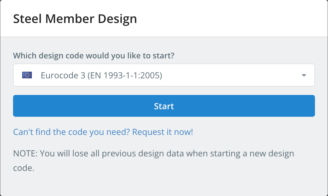
Starting a design code deletes the design data of the previous one. To switch codes later, utilisation Commencer un nouveau code dans le Conception menu.
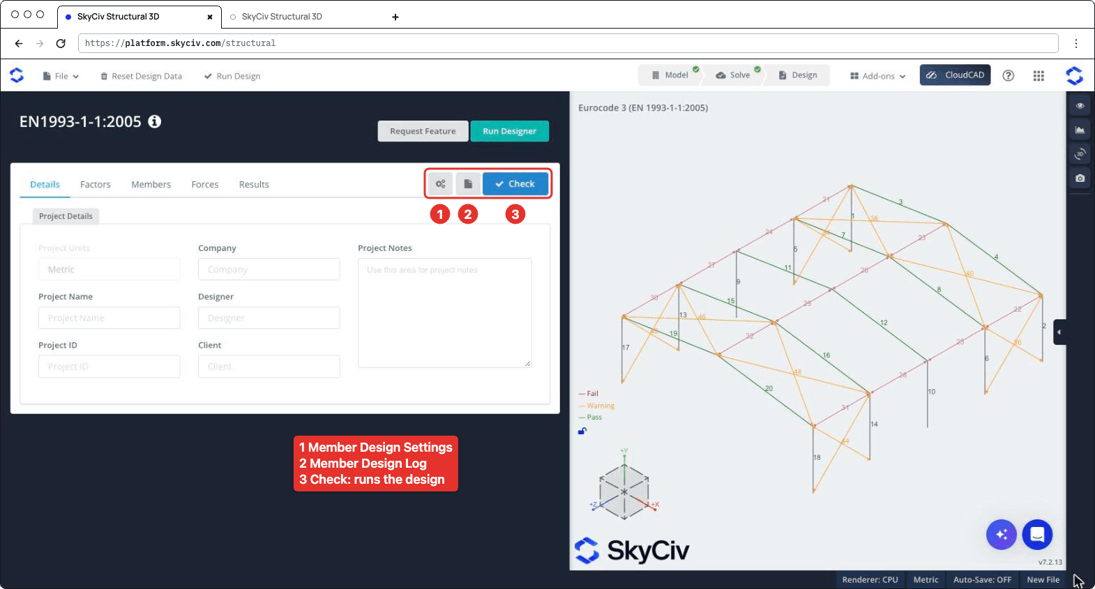
Le panneau de conception s'ouvre sur la gauche, avec le modèle 3D à droite. L'en-tête montre le code, plus Fonctionnalité de demande et Exécuter le concepteur. À droite de la barre d'onglets se trouvent trois boutons: les paramètres (engrenage) bouton, qui ouvre Paramètres de conception des membres, le bouton de journalisation, qui ouvre le Journal de conception des membres, et Vérifier, qui exécute le contrôle de conception. Les onglets sont Détails, Les facteurs, Membrures, Les forces et Résultats.
Paramètres de conception des membres
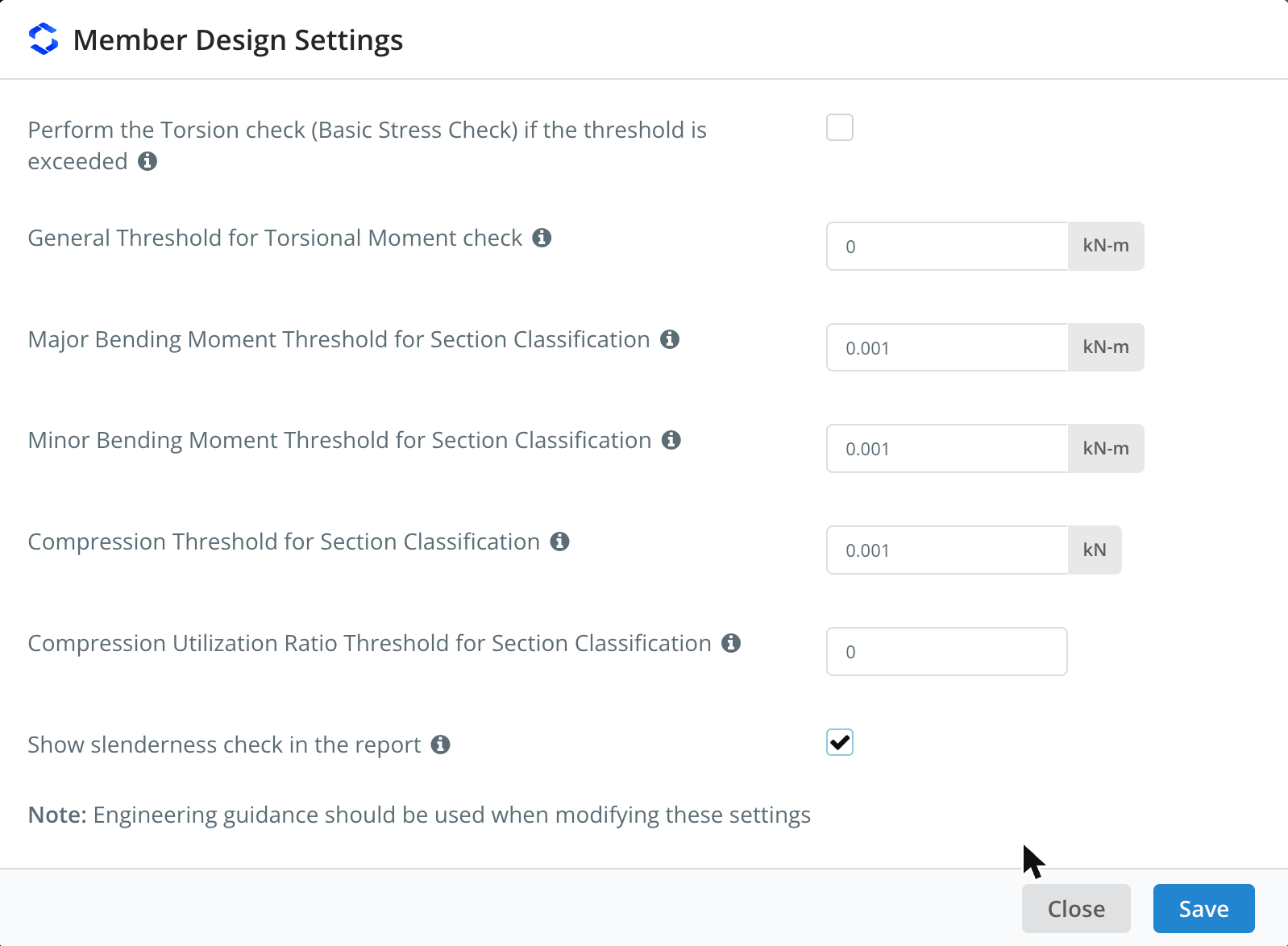
Cliquez sur le bouton d'engrenage pour ouvrir Paramètres de conception des membres. Passez la souris sur l'icône ℹ à côté d'un paramètre pour voir sa description.
| Paramètre | Défaut | La description |
|---|---|---|
| Perform the Torsion check (Vérification du stress de base) if the threshold is exceeded | Décoché | Runs the torsion check of I-shapes and rectangular hollow sections when the torsional moment exceeds the threshold. Lorsque décoché, the torsion check is skipped whatever the threshold |
| General Threshold for Torsional Moment check | 0 kN-m | The torsional moment (in absolute value) above which the torsion check is performed, for all members whose Tlimite est auto dans le Membrures languette |
| Major Bending Moment Threshold for Section Classification | 0.001 kN-m | Bending about the major axis is included in the overall section classification of a limit state only when the moment exceeds this value |
| Minor Bending Moment Threshold for Section Classification | 0.001 kN-m | Le même, for bending about the minor axis |
| Compression Threshold for Section Classification | 0.001 kN | Compression is included in the overall section classification of a limit state only when the compression force exceeds this value |
| Compression Utilization Ratio Threshold for Section Classification | 0 | Compression is included in the overall section classification only when its utilization ratio exceeds this value. It applies to all the limit states other than compression |
| Show slenderness check in the report | Décoché | Adds the slenderness check to the detailed report of each member, voir Slenderness Ratio Check ci-dessous |
The classification thresholds keep very small forces from governing the class of a section: par exemple, a beam with a negligible axial force is not classified as if it were in pure compression. Comme le note la boîte de dialogue, des conseils techniques doivent être utilisés lorsque vous modifiez ces paramètres. Cliquez sur sauver postuler.
Détails
Sur le Détails onglet vous pouvez saisir les détails du projet (Compagnie, nom du projet, Designer, ID de projet, Client et Notes de projet). Vous n'êtes pas obligé de les remplir, but anything you enter is shown in your reports. Unités de projet montre Métrique et ne peut pas être modifié ici.
Les facteurs
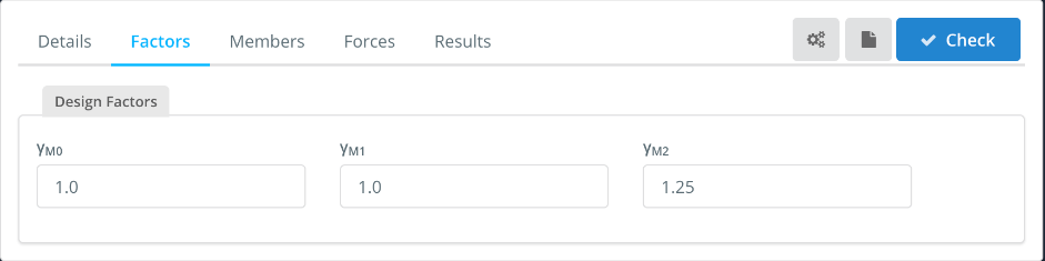
Ce logiciel Les facteurs tab shows the partial factors for resistance, which you can change:
| Facteur | Used for | Défaut |
|---|---|---|
| cM0 | Resistance of cross-sections | 1.0 |
| cM1 | Resistance of members to instability (le flambage) | 1.0 |
| cafin que les ingénieurs puissent revoir exactement comment ces calculs sont effectués | Resistance of cross-sections in tension to fracture (net section) | 1.25 |
Membrures
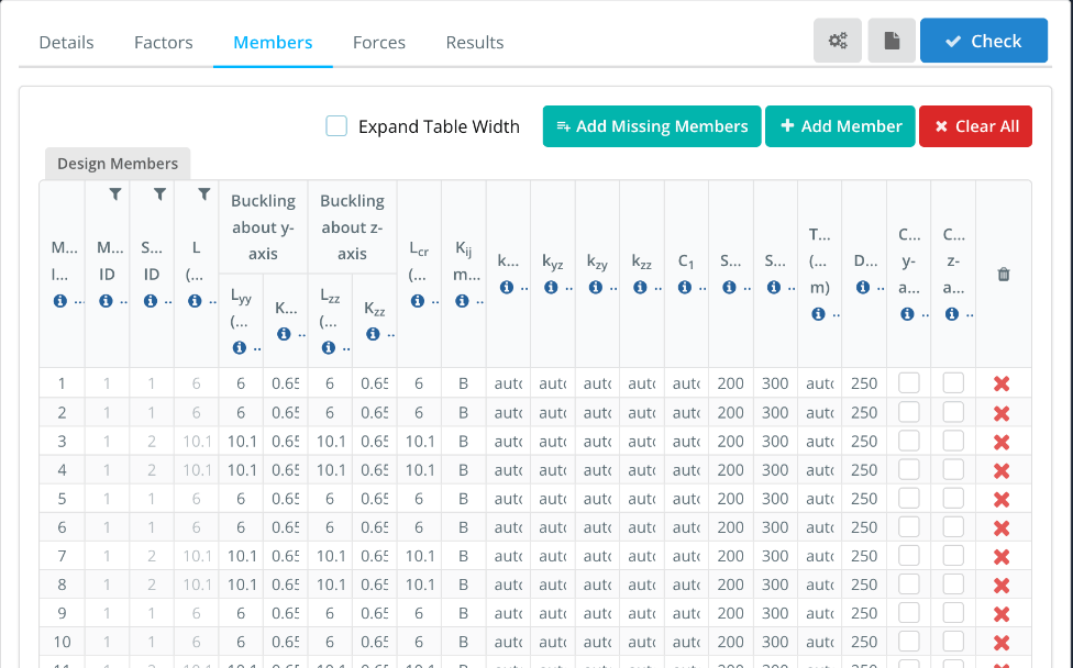
Ce logiciel Membrures l'onglet répertorie les membres de la conception, with one row for each member of the model. ID membres(s), Identifiant du matériau, ID de section et L come from the model. The buckling lengths and the other parameters are filled in with default values that you can change. Hover over the ℹ icon in a column header to see its description.
- Agrandir la largeur du tableau: shows the full column headers and values, with a horizontal scroll bar.
- Add Missing Members, L'onglet est l'endroit où vous pouvez définir tous les membres avec lesquels vous travaillez en cliquant sur l'onglet et Clear All: add the model members that are not in the table, add a design member, or remove all of them. Enter several member IDs, identifier ce type d'élément 3D dans le champ de l'ID, in ID membres(s) to design them as a single design member.
| Colonne | La description | Défaut |
|---|---|---|
| Lyy, Kyy | Buckling length and effective length factor for flexural buckling about the y-y (major) de cet axe, used to calculate Ncr | Lyy = member length, Kyy from the end fixity of the member |
| Lzz, Kzz | Le même, about the z-z (minor) de cet axe | Lzz = member length, Kzz from the end fixity of the member |
| Lcr | Buckling length for lateral-torsional buckling. Enter the member length, or comma-separated lengths, one for each segment between lateral restraints | Longueur du membre |
| Kij méthode | Method used to calculate the interaction factors: A (Annex A, alternative method 1) ou B (Annexe B, alternative method 2) | B |
| kyy, kyz, kzy, kzz | Interaction factors for bending and axial compression (Eq. 6.61 et 6.62). Avec auto, they are calculated with the method chosen in Kij méthode | auto |
| C1 | Moment modification factor for the elastic critical moment Mcr. Avec auto, it is calculated from the bending moment diagram of each segment. Enter a single value for all the segments, or comma-separated values, one for each segment | auto |
| RSC, RST | Slenderness limits in compression and in tension, voir Slenderness Ratio Check ci-dessous | 200, 300 |
| Tlimite | Torsional moment threshold for the torsion check of this member. Avec auto, the general threshold of the settings is used. The torsion check must be ticked in the settings | auto |
| DefL | Rapport d'élancement pour la tension: the member passes when span/deflection is at least this value | 250 |
| Cantilever y-axis, Cantilever z-axis | Tick if the deflection check should consider the member as supported at one end only, for deflection along that axis | Décoché |
Par exemple, pour un 10.1 m rafter with purlins every 2.02 m, Entrer 2.02,2.02,2.02,2.02,2.02 in Lcr. The lengths must add up to the member length (dans 1%). Each segment is then checked for lateral-torsional buckling with its own length and C1. If you enter a single length that is different from the member length, C1 can’t be calculated automatically and must be entered as a number.
Les forces
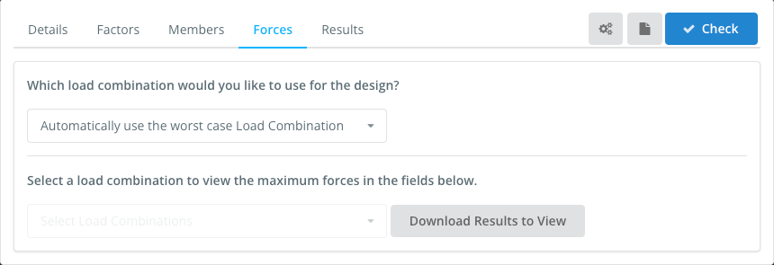
Ce logiciel Les forces tab sets the load combination used in the design. Par défaut, Automatically use the worst case Load Combination checks every strength load combination of the model and reports the worst one for each check. You can also select a single load combination. Serviceability combinations are not listed here: they are used for the deflection check.
To view the forces of a load combination, select it in Select a load combination to view the maximum forces in the fields below, et cliquez Download Results to View.
Résultats
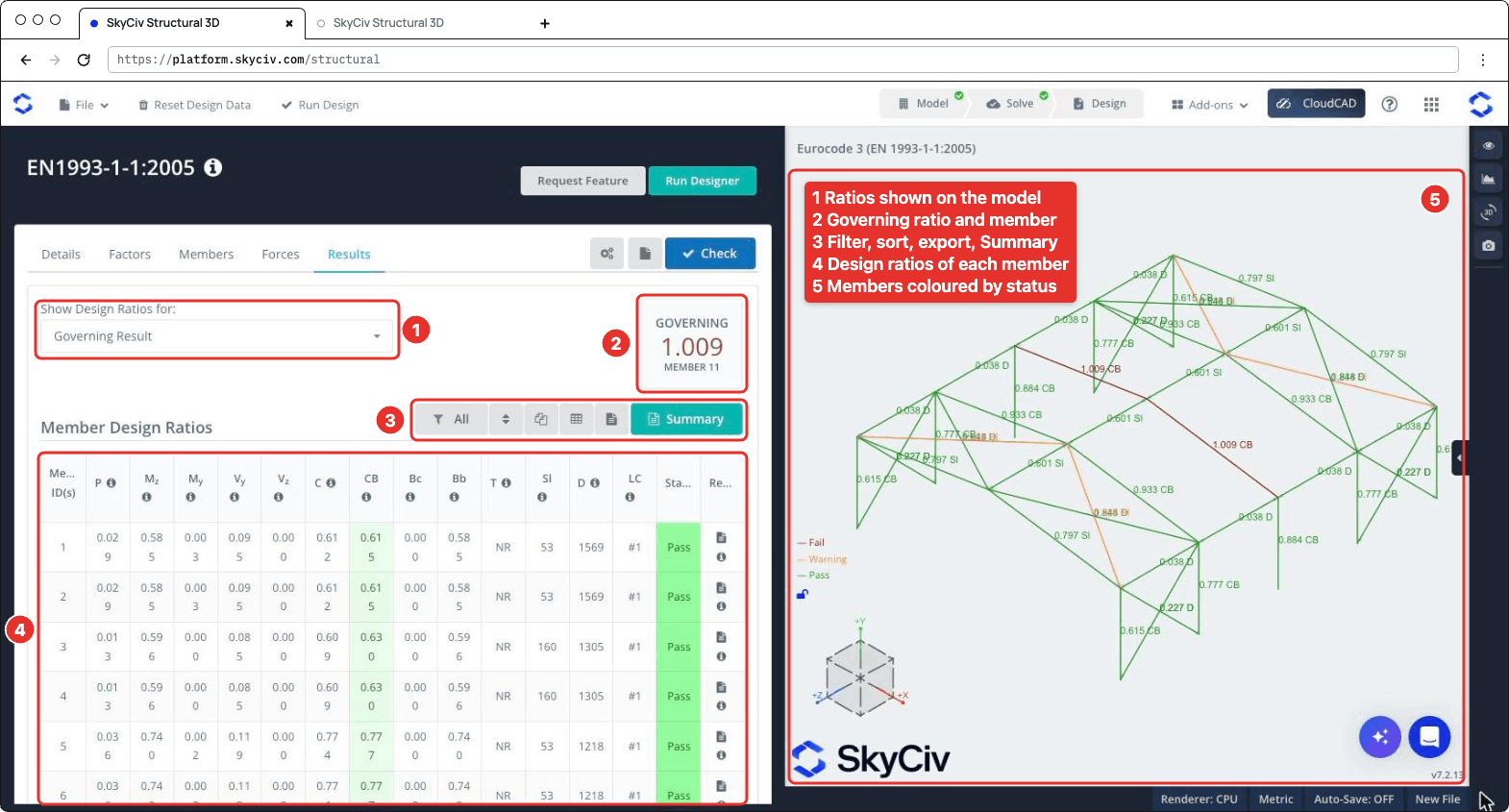
Cliquez sur Vérifier pour exécuter le contrôle de conception. Ce logiciel Résultats l'onglet montre (numbered as in the screenshot below):
- Afficher les rapports de conception pour: chooses which ratios are shown on the 3D model, par exemple Résultat déterminant, Membres ayant échoué, a single check or the Worst Load Combination.
- GOUVERNANT: le ratio le plus élevé et son membre.
- A toolbar to filter the members (Tout, Failed, Passé ou Avertissement les membrures, or the members of a section), reset the sorting, copy the table, download it as CSV, download all the member reports as HTML, et ouvrez le Résumé rapport.
- Ce logiciel Ratios de conception des membres table, avec un Statut (Passer, Warn ou Échouer) and the report icon of each member. Passez la souris sur l'icône ℹ dans un en-tête de colonne pour voir la clause à laquelle elle fait référence.
- The 3D view, where each member is coloured Échouer, Avertissement ou Passer and labelled with its governing ratio and check.
| Colonne | Vérifier | Clause |
|---|---|---|
| P | Axial force, traction ou compression | 6.2.3 ou 6.2.4 |
| Mz | Bending about the major axis | 6.2.5 |
| MY | Bending about the minor axis | 6.2.5 |
| VY, Vz | Tondre | 6.2.6 |
| C | Actions combinées, resistance of cross-sections | 6.2.1 |
| CC | Combined bending and axial compression, buckling resistance of members | 6.3.3 |
| Bc | Buckling resistance of compression members | 6.3.1 |
| Bb | Lateral-torsional buckling resistance | 6.3.2 |
| T | Torsion (basic stress check), NR when it is not performed | 6.2.7 |
| SL | Governing slenderness λ of the member (not a ratio) | |
| D | Span/deflection of the member (not a ratio) | |
| CL | Load combination of the governing result |
A member fails when one of its strength ratios is above 1.0. The slenderness and deflection checks are not part of the governing ratio: when the slenderness exceeds its limit, or the span/deflection is below DefL, l' SL ou D value is highlighted and the member status is Warn. Their ratios to the limits are shown on the 3D model (par exemple 0.797 SL) et dans le Résumé rapport.
Rapports
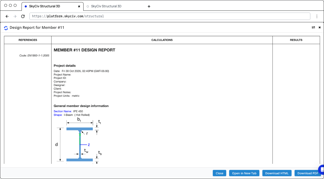
Click the report icon of a member to open its design report, dans un Rapport de conception pour le membre n° n dialoguer avec Fermer, Ouvrir dans un nouvel onglet, Télécharger HTML et Télécharger le PDF. The report shows the references (clauses), the calculations and the result (STATUS PASS ou ÉCHOUER) of each check:
- Détails du projet et General member design information: the section, its shape and fabrication (hot-rolled or welded), the material properties and the design parameters
- Design Internal Forces: the governing forces used for each check
- The checks of axial strength (traction ou compression), axial buckling strength, flexural strength about the major and minor axes, lateral-torsional buckling resistance, interaction of combined resistance, interaction of combined buckling, shear strength along y and z and, when performed, en torsion
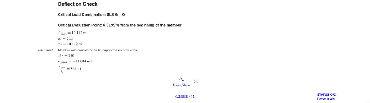
- Vérification de la déflexion: the critical serviceability load combination and position, the span, the maximum deflection and the ratio to the limit
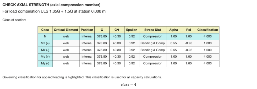
Each check gives the load combination and station that govern it, and the section classification table for that limit state: the class of each element (la toile, brides) for the axial force and for bending about each axis, with the governing class highlighted. Pour une classe 4 section, the effective properties are used. When the shear force is high (6.2.8), the reduced yield strength is used for the resistances.
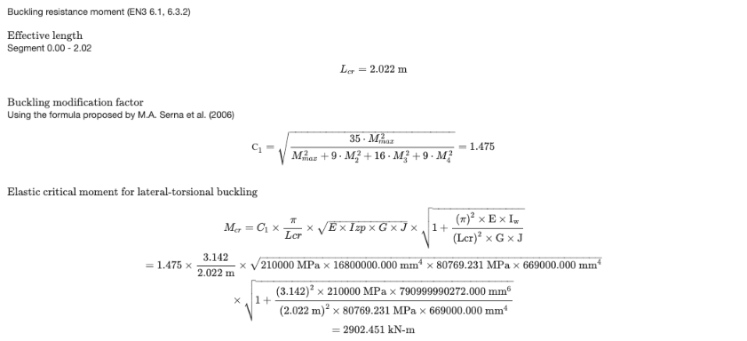
The lateral-torsional buckling check is calculated for the segment where the governing station is, with its Lcr et C1. When C1 est auto, it is calculated from the moments along the segment with the formula proposed by Serna et al. (2006). The report then gives Mcr, the non-dimensional slenderness, the buckling curve and the reduction factor χLT.
The deflection check is performed when the model has serviceability load combinations and DefL est supérieur à 0. Otherwise the report says that the deflection check was skipped.
Cliquez sur Résumé on the Results tab to open the summary report. Il répertorie les détails du projet (code de conception, user name and unit system), the design factors, les matériaux, the section dimensions and properties, the properties of each member (buckling lengths, Lcr, C1, Cm factors and limits), the results of all the members and the definitions of the symbols.
Contrôles effectués
Here are the details of some of the checks performed by the module.
Slenderness Ratio Check
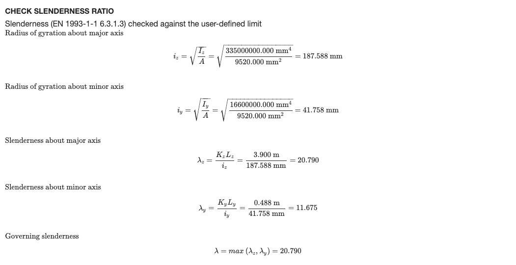
Each member is checked against the slenderness limits entered in the Membrures languette: RSC for members in compression (200 par défaut) et RST for members in tension or without axial force (300 par défaut). The slenderness is calculated about both axes from the effective length and the radius of gyration about the same axis:
- λz = KzLz / jez about the major axis, with iz = √(Iz / A)
- λY = KYLY / jeY about the minor axis, with iY = √(IY / A)
The governing slenderness λ = max(λz, λY) is divided by the limit, and the member passes when this ratio is 1.0 ou moins. The slenderness check is listed in the SL column of the Results tab.
To show this check in the detailed report of each member, open the settings (the gear button next to Vérifier) and tick Show slenderness check in the report. It’s off by default.
The report then has a Check Slenderness Ratio section after the buckling check, with the radii of gyration, the slenderness about each axis, the governing slenderness and its ratio to the compression and/or tension limit, with a PASS or FAIL status.