Dans certains cas, des sections non prismatiques ou coniques sont utilisées dans les éléments structurels pour obtenir une structure plus performante. L'idée derrière les éléments non prismatiques est de fournir progressivement moins de matière et donc moins de capacité dans les parties de l'élément où les forces internes sont plus faibles., et plus de matière dans les parties où les forces internes sont plus importantes. En d'autres termes, les sections coniques tentent de suivre la répartition des forces/contraintes internes le long de l'élément.
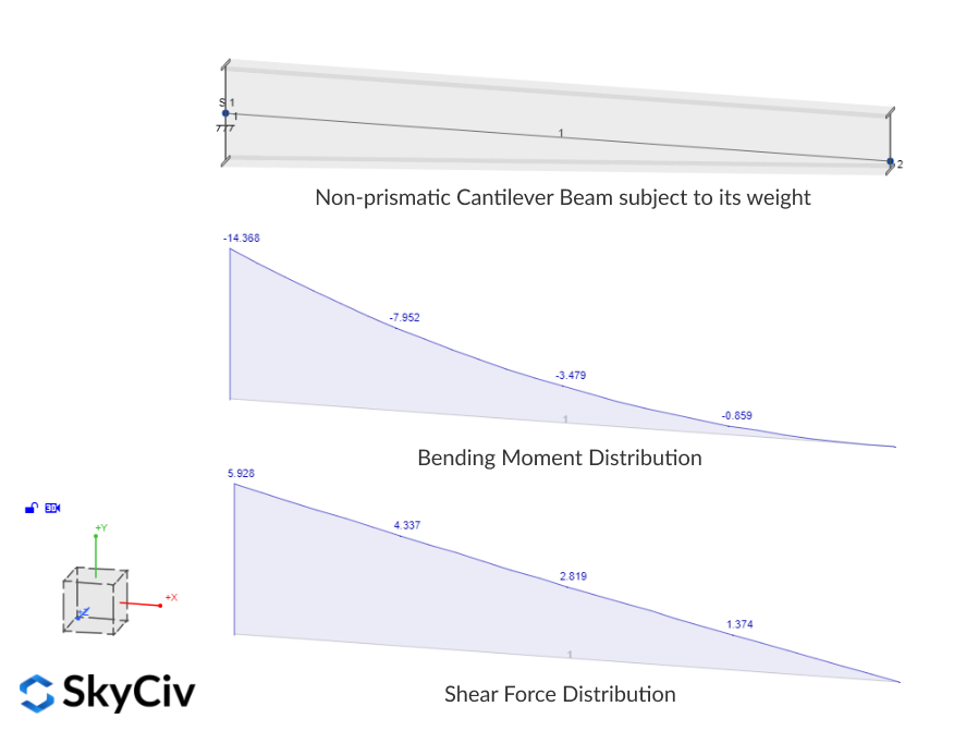
Par exemple, dans une poutre en porte-à-faux soumise à son propre poids, le moment de flexion et l'effort tranchant prennent leurs valeurs maximales à l'extrémité fixe et sont nuls à l'extrémité libre, suivant respectivement une distribution quadratique et linéaire. Dans ce cas, l'extrémité fixe de la poutre demande la capacité maximale tandis que l'extrémité libre n'a aucune demande, pour cette raison, une section conique peut aider à économiser du matériel et à utiliser efficacement la capacité disponible.
Il y a un autre article qui explique en détail comment modéliser des sections et des jarrets non prismatiques ou effilés et comment la variation de section linéaire est idéalisée avec des éléments prismatiques plus courts au stade de l'analyse. Dans cet article, nous nous concentrerons sur la façon dont le module de conception des membres SkyCiv traite les sections non prismatiques lors de l'exécution des vérifications de conception. En ce moment, il existe quelques sections non prismatiques entièrement prises en charge dans le logiciel:
- Boîtes non prismatiques formées à froid (sections creuses rectangulaires composées de deux canaux à lèvres) selon AS/NZS 4600:2018
- Plaques soudées Poutre en I non prismatique selon AS 4100:2020 et NZS 3404:1997
Dans ces codes, il existe deux types de contrôles différents qui doivent être effectués dans différents états limites: vérifications de sections et vérifications de membres ou de segments. Avant de plonger dans chaque groupe de contrôles, passons rapidement en revue les informations disponibles sur les sections qui proviennent de l'étape d'analyse.
Propriétés des sections disponibles
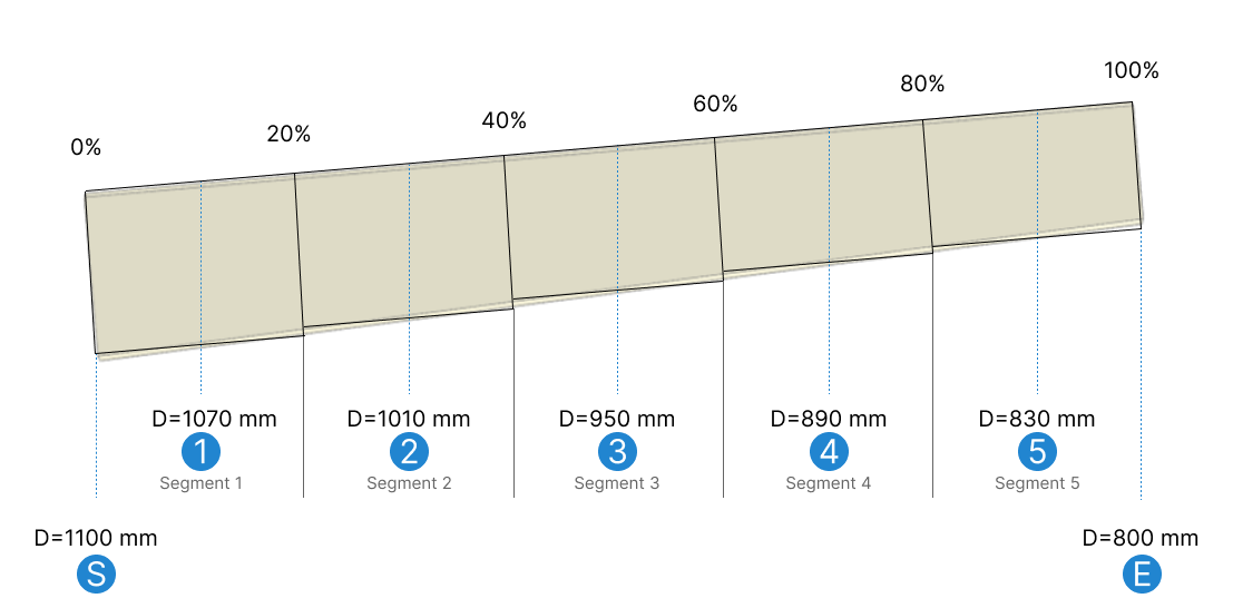
En supposant que la section conique ait été configurée avec “moyenne” tailles des éléments prismatiques et 5 segments prismatiques, Il y aura 7 gares (représenté sous forme de lignes pointillées bleues dans le diagramme ci-dessous) avec propriétés de section calculées/connues, correspondant aux sections qu'aurait un élément non prismatique à variation linéaire au milieu de chaque segment prismatique. Ceci est montré dans l'image ci-dessous intitulée S (forme de départ), 1, 2, 3, 4, 5, et E (forme d'extrémité). Pour l'exemple, faisons varier la profondeur de la section de 1010 mm à 800 mm.
Vérifications de sections
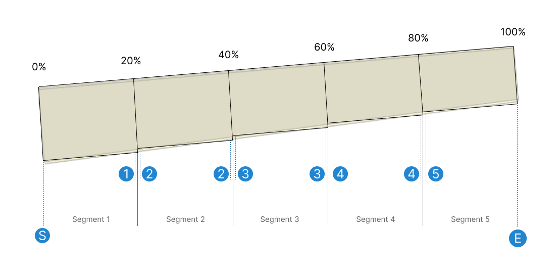
Les contrôles des sections sont effectués station par station en utilisant la capacité de la section à la station donnée et les efforts internes qui agissent individuellement ou combinés exactement à cette position le long de l'élément.. Chaque station utilisera les propriétés de section du segment prismatique auquel appartient la station.. Juste au niveau des segments prismatiques’ variation, il y aura deux stations au même endroit avec une section différente, une station appartenant au segment à gauche de la variation et l'autre à droite de la variation:
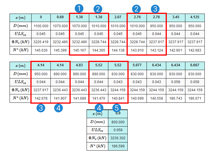
C'est pourquoi dans le rapport de conception, il y a des stations répétées avec deux valeurs de capacité différentes., chaque station utilise une section différente et peut donc produire des résultats différents. Ainsi, les postes de contrôle final comprennent (a) les points d'évaluation des résultats d'analyse et (b) le nombre total de stations plus en utilisant la logique ci-dessus:
Chèques des membres
Pour les vérifications de membres ou de segments, les segments individuels sont définis par les dispositifs de retenue latéraux spécifiés par l'utilisateur. Ces contraintes proviennent d'autres éléments en contact avec l'élément de conception, tels que les pannes et les contreventements qui aident à prévenir le flambement de l'élément. Pour les chèques membres, les efforts internes utilisés sont les résultats maximaux présents dans le segment, peu importe s'ils se produisent à différentes positions le long du membre. La section utilisée pour la capacité est choisie parmi les sections disponibles selon l'un des critères suivants:
- Section critique: Section de la station avec le taux d'utilité le plus élevé d'après la vérification de la section.
- Section minimale: Section avec la superficie/capacité la plus faible.
- Section mi-longue: Section la plus proche de la mi-portée géométrique du segment.
Par exemple, prenons un segment qui, en raison des dispositifs de retenue latéraux attribués, s'exécute à partir du milieu du segment 2 (30%), au milieu du segment 4 (70%) comme le montre l'image ci-dessous.
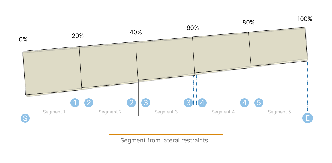
En supposant que la station critique pour ce segment se trouve au début du segment (le milieu du deuxième segment prismatique global – 30% de l'ensemble du membre), la section utilisée pour la capacité dans le chèque de membre sera:
- Section critique: Section 2
- Section minimale: Section 4
- Section mi-longue: Section 3, qui est la section disponible la plus proche du 50% du segment de retenue latérale (milieu du troisième segment prismatique global)