
Les connexions en acier répertoriées dans cet article sont conçues conformément à la norme australienne AS 4100:2020, Manuel de connexion de l'Institut australien de l'acier 1, et les guides de conception de l'Australian Steel Institute 1-5.
Portée du SA 4100 Module
Avant de passer en revue les types de connexion, il vaut la peine d'être clair sur ce que couvre le module sous AS 4100.
AS 4100:2020 la conception dans SkyCiv est destinée aux connexions de cisaillement entre les sections en I, en unités métriques. Connexions momentanées, les épissures et les connexions de contreventement sont en dehors de l'AS actuel 4100 portée.
Poutre universelle à colonne universelle
Les assemblages poutre-poteau font partie des types d'assemblage les plus courants dans la conception en acier.. Les connexions AS dans SkyCiv sont construites autour d'une poutre supportée encadrant un élément de support, et l'orientation peut être définie sur un support de bride de colonne, un support web colonne, ou un support d'âme de poutre.
Cette troisième orientation signifie que les quatre mêmes types de connexion peuvent également être utilisés poutre à poutre., non seulement poutre à colonne.
Une seule connexion à un nœud peut être conçue à la fois. Lorsqu'il s'agit de connexions dos à dos, il est conseillé de prendre des hypothèses conservatrices sur le chemin de charge.
Connexions de cisaillement
Une connexion par cisaillement est une connexion simple. Il est détaillé de supporter la réaction d'extrémité de la poutre et de tourner au niveau de l'assemblage plutôt que de supporter le moment d'extrémité., c'est ce qui le sépare d'un moment de connexion. Dans le module AS, il est conçu uniquement pour le cisaillement, sans charge axiale concomitante.
Pour la conception AS, les types d'assemblages de cisaillement suivants sont disponibles:
Chacun des quatre est disponible poutre-aile de poteau, âme de poutre à poteau, et âme poutre à poutre.
-

- Plaque latérale Web – Poutre à bride de colonne
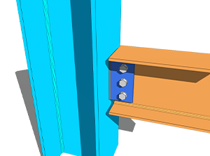
-
- Plaque latérale Web – Ame poutre-poteau
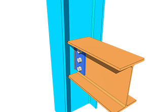
-
- Plaque d'extrémité flexible – Poutre à bride de colonne

-
- Plaque d'extrémité flexible – Ame poutre-poteau
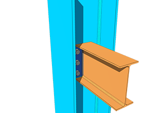
-
- Angle unique – Poutre à bride de colonne
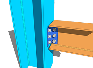
-
- Angle unique – Ame poutre-poteau
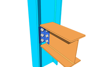
-
- Angle double – Poutre à bride de colonne
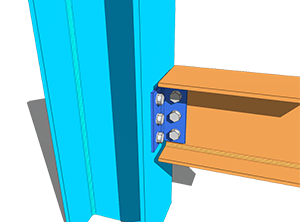
-
- Angle double – Ame poutre-poteau
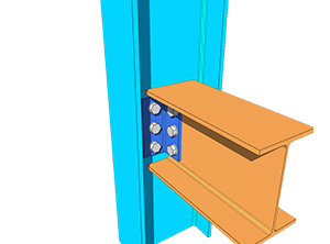
La conception des assemblages de cisaillement ci-dessus était principalement basée sur les guides de conception ASI. 3, 4 et 5. Les formules de référence sont tirées de l'AS 4100:2020 manuel, tandis que le reste des calculs et des critères ont été tirés du ASI Connection Handbook 1.
Coefficient de groupe de boulons
Pour plus de flexibilité sur la disposition des boulons et l'espacement des boulons, SkyCiv a adapté la méthode ICOR et l'analyse inélastique pour déterminer le coefficient de groupe de boulons C, qui est ensuite utilisé pour calculer la capacité de cisaillement du groupe de boulons et la capacité portante des boulons.
La méthode du centre de rotation instantané (ICOR) utilise l'itération pour localiser l'IC du groupe de boulons. SkyCiv utilise son propre solveur pour ces itérations. L'emplacement du CI est inclus dans les calculs, mais les itérations ne sont pas affichées, pour que le rapport reste concis et lisible.
L'équation utilisée pour calculer la force par boulon à l'aide de l'analyse inélastique est basée sur l'AISC Eq. (7-1) sur la page 7-7 du manuel AISC 15e édition. L'équation est indiquée ci-dessous.
[math] R = R_{ult}\left(1-e^{-10\Delta}\right)^{0.55} [math]
Il s'agit d'une méthode empruntée au solveur de groupe de boulons, pas un changement de code de conception. Les capacités elles-mêmes sont toujours vérifiées chez AS 4100:2020.
Étant donné que la capacité du groupe de boulons a adapté la méthode AISC, les dispositions permettant de déterminer l'excentricité de conception des boulons du groupe de boulons suivent également le tableau 10-9 de l'AISC 15e édition. Cela s'applique à la connexion AS Web Side Plate de SkyCiv.
L'excentricité est gérée différemment pour chaque type. Pour les connexions à angle unique, les pieds NSL et OSL sont conçus avec une excentricité de charge. Pour les connexions à double angle, seul le pied NSL est conçu avec excentricité, puisque la jambe OSL est symétriquement équilibrée par rapport à la ligne de force. Pour les connexions avec plaque d'extrémité flexible, il n'y a pas non plus d'excentricité, car la charge agit directement sur le centre du groupe de boulons. Chaque groupe de boulons sans excentricité prend le coefficient de boulon C comme nombre total de boulons dans le groupe..
Types de luminaires
Chaque interface peut être définie comme un élément boulonné ou soudé, à la poutre et au support.
Pour le boitier boulonné, voir la documentation sur boulons; pour le boitier soudé, voir soudures.
Limitations détaillées
Limites détaillées, les contrôles d'aménagement des connexions, sont inclus dans la conception de la connexion AS. La plupart d'entre eux sont basés sur les guides de conception ASI 3-5, tandis que certains suivent une approche d'ingénierie intuitive.
Ces contrôles détectent la connexion qui satisfait à tous les calculs de résistance et qui ne peut toujours pas être construite ou érigée., qui est un mode de défaillance que les contrôles de force seuls ne trouveront pas.
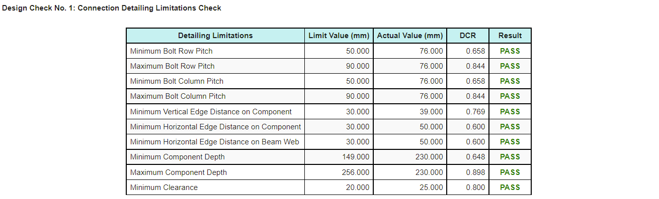
Un résultat de réussite ou d'échec pour les limitations détaillées apparaît dans l'onglet Résultats., afin qu'il puisse être identifié rapidement. Le rapport de calcul produit également un tableau, indiquée ci-dessous, donc l'élément qui doit être modifié est facile à sélectionner.
Plus de types de connexion
Si vous souhaitez voir plus de types de connexion ajoutés sous AS 4100, vous pouvez contacter Assistance SkyCiv.
Essayez-le maintenant
Choisissez une plaque latérale Web, plaque d'extrémité flexible, angle simple ou double angle, entrez votre faisceau, support et charges, et le module renvoie chaque chèque avec son taux d'utilisation et la référence derrière celui-ci, avec le tableau de limitation détaillé. Il s'exécute dans le navigateur, avec rien à installer, et tu peux le faire sans compte.
Vous pouvez également y accéder via le Calculateur de conception d'assemblages en acier gratuit.
Inscrivez-vous au compte gratuit
Un compte gratuit vous permet de sauvegarder et de recharger vos fichiers de connexion, ce que l'outil gratuit ne fait pas. Il vous donne également accès au reste de SkyCiv. logiciel structurel, y compris la 3D structurelle.
Conception de connexion autonome
Vous souhaitez utiliser uniquement le module de conception de connexion? Cliquez sur le bouton ci-dessous pour le prix autonome.
