
The double angle connection is one of the simple shear connections set out in Part 10 of the AISC Manual, and a fabricator favourite at beam to column web connections.
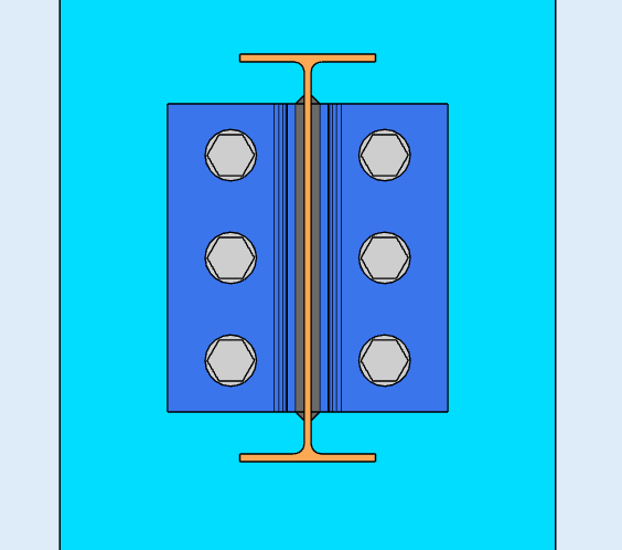
It consists of two angles, one each side of the beam web, bolted or welded to the beam web and to the support. On a beam to column web connection the angles are usually welded to the beam and bolted to the support. That combination needs a shorter leg on the support side, which matters when the space inside the column web is tight and an all-bolted detail would need clearance for a wrench.
An all-bolted double angle is the usual choice at a beam to girder connection, particularly where a angle unique will not carry the shear: the second angle gives the support bolts two shear planes instead of one.

The three arrangements are all-bolted, bolted with the angles welded to the supporting beam, and bolted with the angles welded to the support. Where the angles are welded, weld returns are required across the top of the angles per Specification Section J2.2b.
What Governs the Design
The double angle is popular because it goes together in the field with ordinary tools and needs no special fabrication. Designing it still comes down to a handful of things that interact.
Bolt spacing drives the bolt group. Too few bolts and the bolts and angles are overstressed; too many and you are paying for a connection that is harder to install than it needs to be. Edge distances matter for the same reason, both from the angle edge and between adjacent bolts, since a short edge distance fails in tear-out long before the bolt fails in shear.
The angles themselves deform. A simple shear connection has to rotate as the beam end rotates, and the angle legs bend to let it. That flexibility is the point, but taken too far it turns into lost capacity and overstressed bolts, which is why the angle thickness and leg length are as much a part of the design as the bolt group.
The design also depends on how the beam is supported. A simply supported beam and a continuous beam put different demands on the same detail.
Designing a Double Angle Connection in SkyCiv
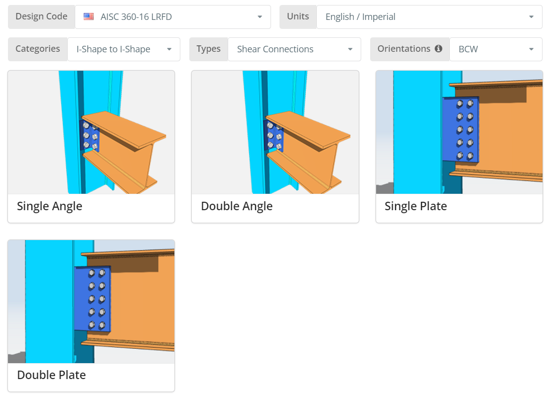
Le code de conception peut être AISC 360-16 ASD ou LRFD, et unités anglais/impérial ou SI/métrique. Orientation is BCF, BCW ou BBW; hover the tooltip for what each one means. Clique le “Angle double” tuile.
Détails Onglet
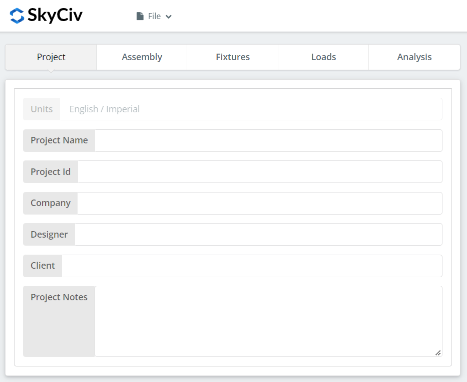
Enregistrez les détails du projet ici. Rien de tout cela ne change les calculs, mais cela se reflète dans le rapport.
Onglet Assemblage
Trois onglets se trouvent sous Assemblage: the Column, the Beam, et la connexion, which holds the double angle.
Onglet Colonne
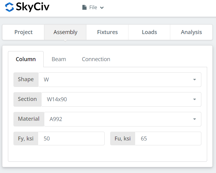
Specify the section and material grade of the column. A992 et A36 sont dans la liste; pour tout le reste, choisissez Custom et entrez Fy et Fu.
Onglet Faisceau
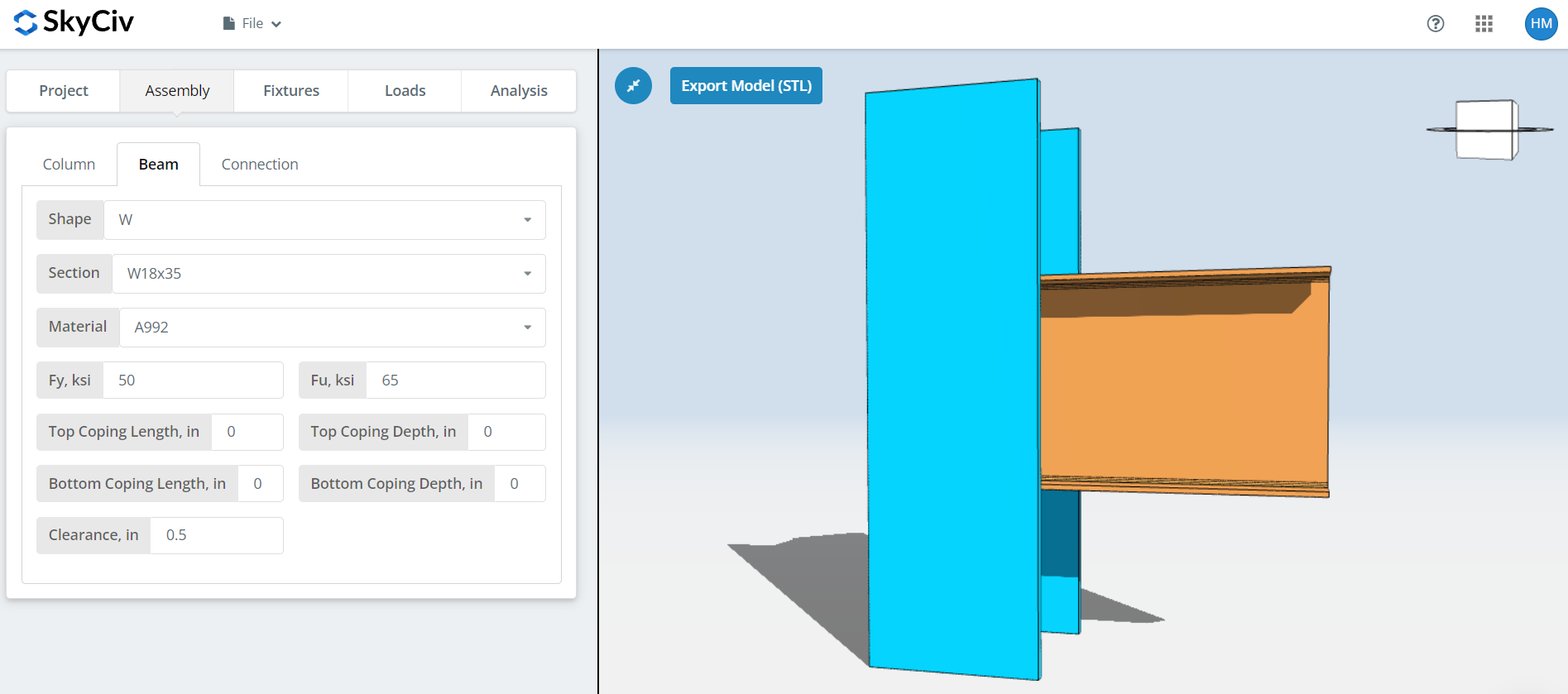
The same inputs for the beam, plus cope dimensions and beam clearance. Add a cope where the beam frames into a supporting member of similar depth and the flange has to be cut back, since the coped section governs checks the uncoped one does not.
Onglet Connexion
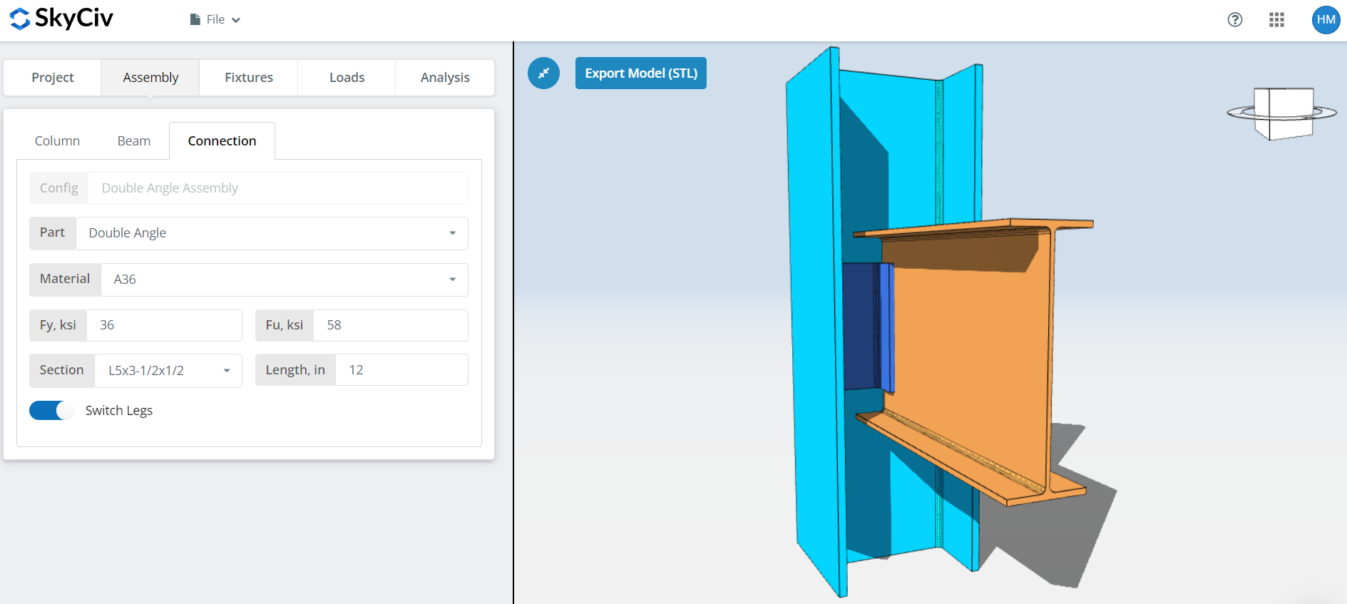
Set the angle properties: grade A36 or A992, ou personnalisé avec vos propres Fy et Fu, then the section size and length. Where the angle has unequal legs you can switch which leg goes where. Pour BCW, put the shorter leg on the column side, because that is where the space runs out.
Watch the 3D renderer as you go. The angle height should sit within the beam depth, and the total angle width should not exceed the column T-dimension or the clear web depth.
Fixation 1 Languette
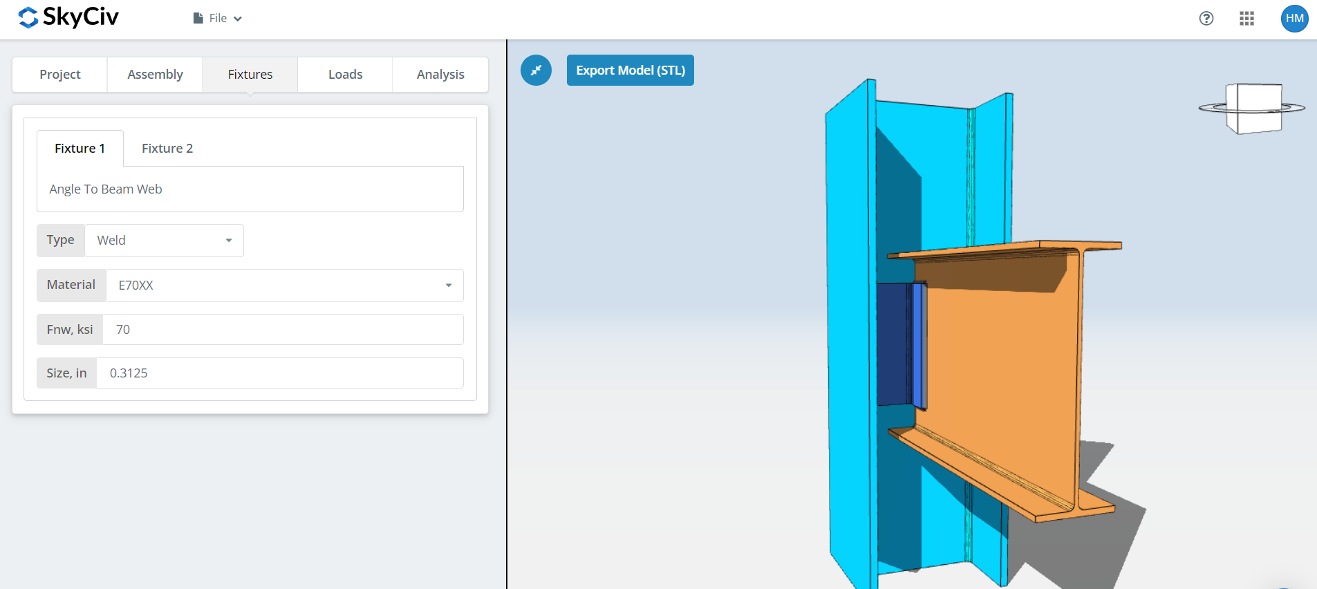
This is the angle to beam web connection. It can be bolted or welded; this walkthrough uses welded, since for BCW a welded-to-beam, bolted-to-support double angle is the arrangement that fits the column web.
Specify the weld material, or choose ‘Custom’ and enter Fnw if the electrode you want is not listed. Then the weld size. Keep the weld size no larger than the angle thickness, or there is no room to lay the weld.
Fixation 2 Languette
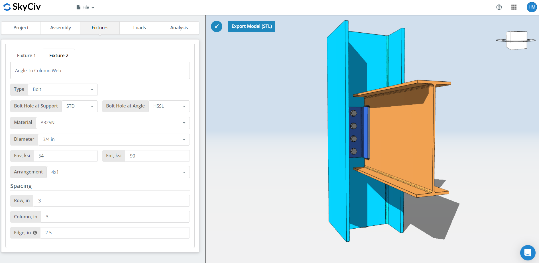
This is the angle to support connection, whether that support is a girder web, a column flange or a column web. Bolted or welded again; this walkthrough uses bolted.
Première, the bolt hole types at the beam and at the angle. Les fabricants demandent généralement des trous standards (MST) in the member and horizontal short-slotted holes (CSSS) in the angle, qui achète une tolérance adaptée sur le terrain.
Prochain, le matériau ou la qualité du boulon: A307, A325, A490 ou personnalisé. A325 et A490 sont des qualités conformes à la norme ASTM F3125, qui a consolidé les anciennes spécifications autonomes. Entre N et X, X donne une plus grande capacité de cisaillement des boulons, mais les fils doivent être exclus du plan de cisaillement, and the erector has to know that.
Puis le diamètre du boulon, à partir du 5/8″ à 1-1/2″ ou les équivalents métriques, et l'arrangement, Jusqu'à 12 rangées et colonnes de boulons, with the row and column spacing.
Worth knowing: if you need more bolt group capacity, opening up the spacing can do it instead of adding bolts, as long as the angle height still fits within the beam depth. The bolt group strength uses the instantaneous centre of rotation method (ICOR), so a wider spacing is credited with the capacity it actually provides rather than rounded down to a table value. Check with your fabricator first, cependant. Many prefer 3″ spacing typical throughout and will price variable spacing accordingly.
Ce logiciel “bord” input here is the horizontal distance from the centre of the beam to the nearest bolt.
Pour en savoir plus côté fixations, voir la documentation sur boulons et soudures.
Onglet Charges
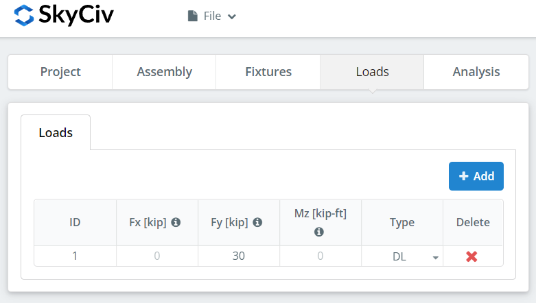
Enter the vertical shear under ‘Fy’.
Match the load to the design method you picked at the start. LRFD prend des charges pondérées par rapport à la résistance de conception; ASD supporte les charges de service par rapport à la résistance autorisée. Le logiciel ne peut pas savoir ce que vous avez tapé.
Onglet Résultats
Cliquez sur “Exécuter des vérifications de conception”. Tout ce qui manque dans les onglets précédents est signalé ici plutôt que par défaut..
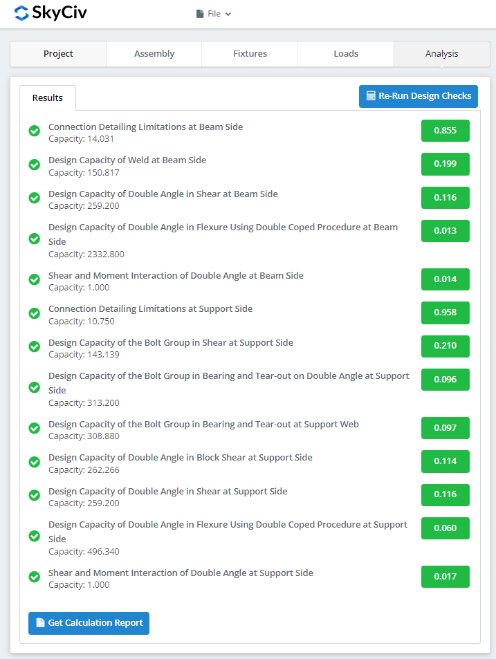
Le résumé montre si la connexion a réussi, avec un taux d'utilisation pour chaque chèque. S'il a échoué, modifiez les entrées dans les onglets précédents et cliquez sur “Réexécuter les vérifications de conception”. Quand ça passe, “Afficher le rapport de calcul” ouvre le rapport détaillé.
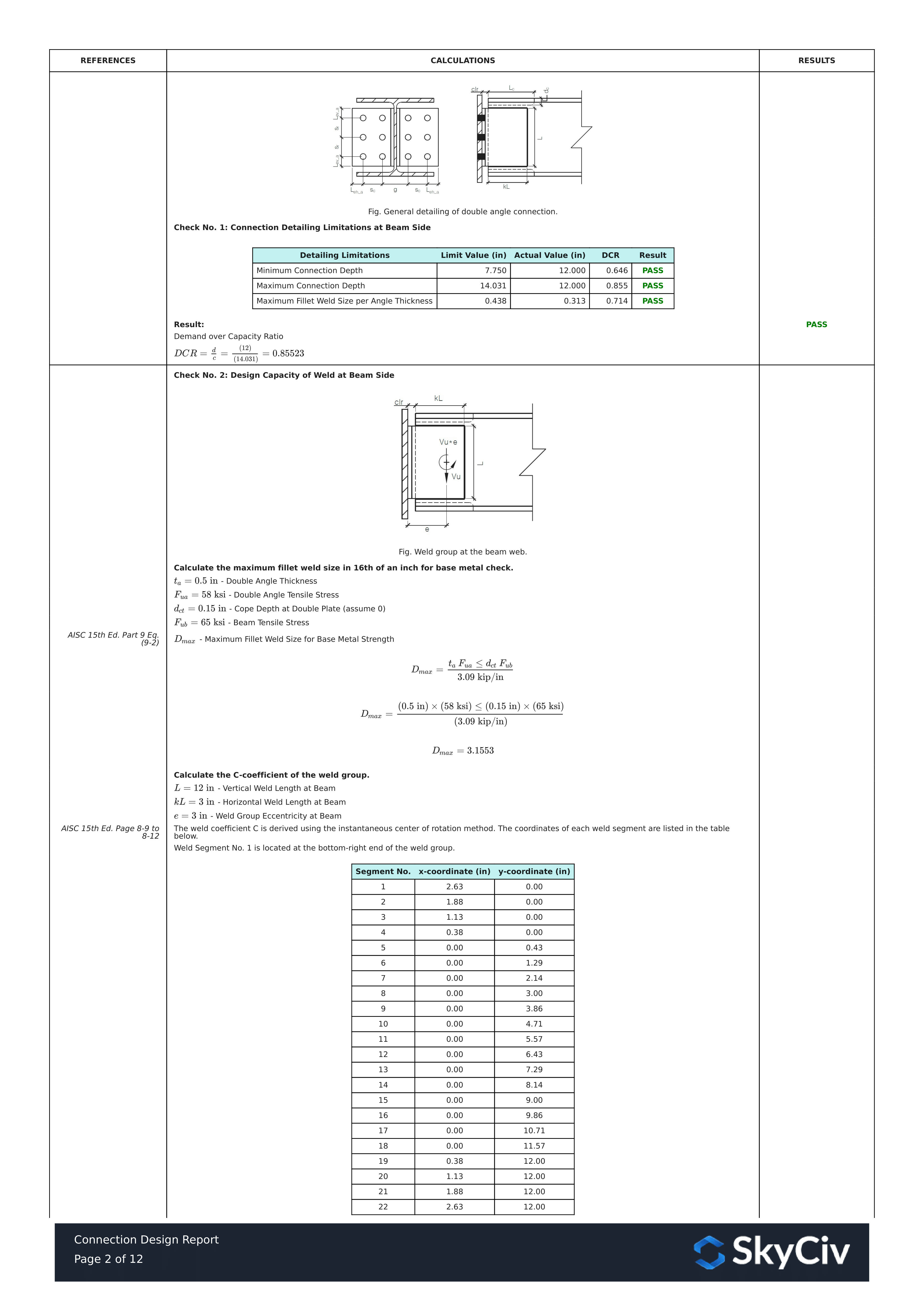
C'est un extrait du rapport. Chaque contrôle porte sa référence au manuel ou à la spécification AISC, and the working follows the same order the specification uses, afin qu'un ingénieur réviseur puisse le lire ligne par ligne au lieu de procéder à une ingénierie inverse d'un nombre.
Voici une copie PDF du rapport de calcul détaillé complet: Rapport de conception de connexion.
Essayez-le vous-même
Pick the double angle, entrez vos rubriques, angle size, bolts and shear, et voir chaque chèque avec sa référence de code. Il s'exécute dans le navigateur, avec rien à installer.
Voir aussi le double angle connection calculator et la connexions de cisaillement overview.
