
Dans la conception de connexion en acier, boulons sont généralement conçus comme un groupe de boulons qui agit comme un seul corps pour résister à une charge donnée. La force d'un groupe de boulons est normalement définie par la force de contrôle de son boulon le plus critique.. Les charges directes sont réparties sur le nombre total de boulons, tandis que le moment induit dû à l'excentricité de la charge est distribué en fonction du moment d'inertie du groupe de boulons et de la distance par rapport au centre de gravité.. C'est ce qu'on appelle l'analyse élastique. En raison de ses hypothèses simplifiées et conservatrices sur la répartition des charges, il donne souvent des assemblages boulonnés surdimensionnés.
Quand on parle d’ingénierie de valeur et de conceptions économiques, l'approche inélastique est préférée par la plupart des fabricants. Il nécessite moins de boulons pour la même ampleur de charge. Pour faire l'approche inélastique, le centre de rotation instantané (ICOR) méthode utilisant des itérations est la meilleure façon.
Dans cet article, nous montrons comment calculer la force d'un connexion boulonnée en utilisant la méthode ICOR. Les réactions par boulon sont calculées à l'aide de l'équation (7-1) sur la page 7-7 du manuel AISC 15e édition. Ceci est ensuite utilisé pour vérifier si l'emplacement supposé du centre instantané du groupe de boulons est correct.. Ensuite, une fois que nous avons le bon emplacement IC, nous calculons le coefficient du groupe de boulons C pour déterminer sa résistance.
Travaillé à la main, la méthode ICOR est un long processus, parce que trouver le centre instantané (CI) c'est des essais et des erreurs. Avec un solveur informatique, le CI d'un groupe de boulons est trouvé par des itérations programmées.. Ce logiciel Solveur de groupe SkyCiv Bolt utilise une méthode d'itération rapide pour déterminer l'emplacement du circuit intégré et le coefficient du groupe de boulons en quelques secondes. Il est utilisé à la fois par l'AISC et l'AS 4100 modules de connexion.
L'exemple concret ci-dessous est le même calcul effectué par le solveur., montré une longue main pour que vous puissiez suivre ce qu'il fait.
Obtenir les propriétés du groupe de boulons
Commençons par une analyse simple d’un groupe de quatre boulons chargés avec une charge de cisaillement verticale excentrique de 10 kips. L'excentricité de la charge le long de l'axe x est 4 pouces à droite du groupe de boulons. L'angle par rapport à la verticale est nul et l'excentricité le long de l'axe y est nulle.
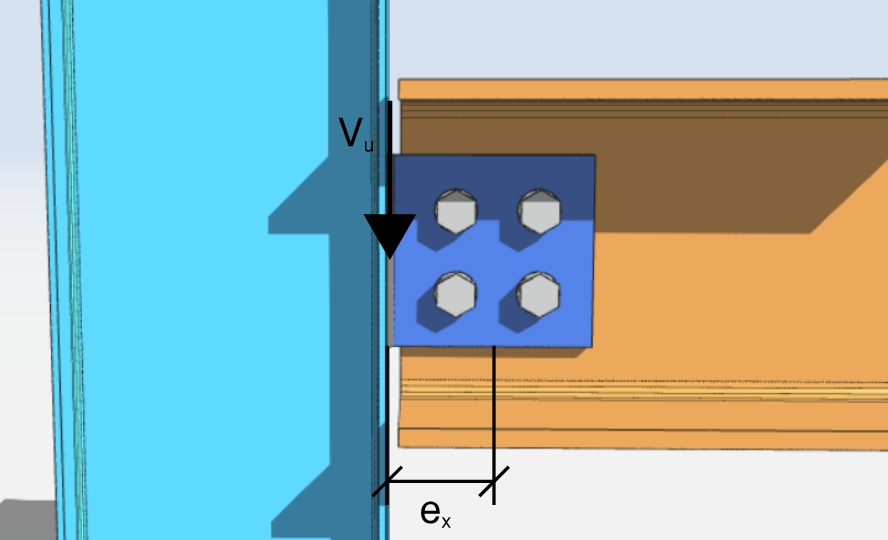
[math] V_{u} = 10\,kips [math]
[math] \theta = 0\,deg [math]
[math] e_{x} = 4\,in [math]
[math] e_{y} = 0\,in [math]
La première chose à faire est d'obtenir les coordonnées de tous les boulons du groupe. Des guides visuels et des tableaux sont fortement recommandés.
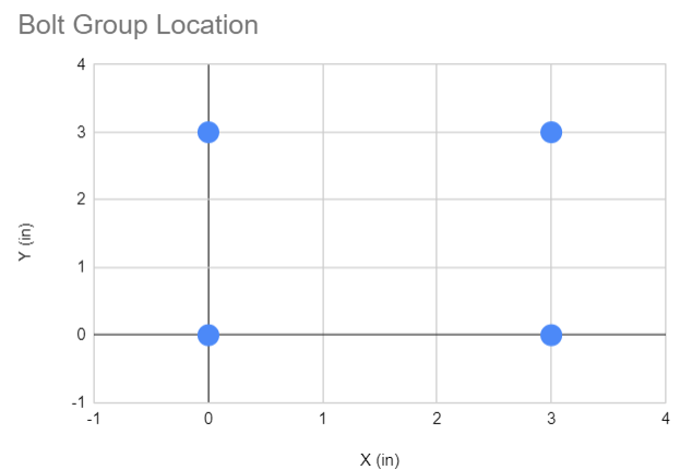
| Identifiant du magasin | X (in) | Y (in) |
| 1 | 0 | 0 |
| 2 | 0 | 3 |
| 3 | 3 | 0 |
| 4 | 3 | 3 |
Pour obtenir le centre de gravité du groupe de boulons le long des axes x et y, nous avons besoin de la formule ci-dessous.
Laisser [mathin] n [mathin] = nombre total de boulons
[math] X_{CG} = \frac{\sum X}{n} [math]
[math] Y_{CG} = \frac{\sum Y}{n} [math]
ensuite, notre solution est:
[math] X_{CG} = \frac{\sum X}{n} = \frac{0\,in + 0\,in + 3\,in + 3\,in}{4} = 1.5\,in [math]
[math] Y_{CG} = \frac{\sum Y}{n} = \frac{0\,in + 3\,in + 0\,in + 3\,in}{4} = 1.5\,in [math]
Supposons l'emplacement de l'I.C.
Après avoir obtenu le centroïde, on suppose l'emplacement du centre instantané (CI). Comme un premier essai, nous pouvons supposer que le CI se trouve au centre de gravité géométrique du groupe de boulons.
Donc, présumer
[math] X_{IC} = X_{CG} = 1.5\,in [math]
[math] Y_{IC} = Y_{CG} = 1.5\,in [math]
Ensuite, nous comptons le déplacement de chaque boulon du CI. Obtenez d'abord la distance le long de x et la distance le long de y, alors le déplacement résultant.
| Identifiant du magasin | cx (in) | cy (in) | c (in) |
| 1 | -1.5 | -1.5 | 2.121 |
| 2 | -1.5 | 1.5 | 2.121 |
| 3 | 1.5 | -1.5 | 2.121 |
| 4 | 1.5 | 1.5 | 2.121 |
Où,
[math] c_{x} = X_{i} – X_{IC} [math]
[math] c_{y} = Y_{i} – Y_{IC} [math]
[math] c = \sqrt{ {\left( c_{x} \right)}^{2} + {\left( c_{y} \right)}^{2} } [math]
Pour Boulon Non. 1, notre solution est
[math] c_{x} = 0\,in – 1.5\,in = -1.5\,in [math]
[math] c_{y} = 0\,in – 1.5\,in = -1.5\,in [math]
[math] c = \sqrt{ {\left( -1.5\,in \right)}^{2} + {\left( -1.5\,in \right)}^{2} } = 2.121\,in [math]
Calculer la déformation par boulon par rapport à la distance de IC
Après avoir obtenu les distances des boulons par rapport à l'emplacement supposé du CI, on calcule la déformation de chaque boulon en fonction de sa distance.
La déformation maximale par boulon, [mathin] \Delta_{max} = 0.34\,in [mathin], est basé sur des données expérimentales pour un boulon ASTM tel que décrit dans la page AISC 7-8. Par proportion linéaire, et réglage [mathin] \Delta_{max} = 0.34\,in [mathin], nous pouvons calculer la déformation d'un boulon individuel par rapport à sa part de la distance maximale [mathin] c_{max} [mathin]. L'équation pour obtenir [mathin] \Delta [mathin] est montré ci-dessous.
[math] \Delta_{1} = 0.34\,in \times \left( \frac{c}{c_{max}} \right) [math]
Pour Boulon Non. 1, la déformation est
[math] \Delta_{1} = 0.34\,in \times \left( \frac{2.121\,in}{2.121\,in} \right) = 0.34\,in [math]
Parce que le CI a été supposé au centre de gravité, les quatre boulons sont à la même distance, donc tous les quatre atteignent la même déformation. Les déformations calculées sont tabulées ci-dessous.
| Identifiant du magasin | [mathin] \Delta [mathin] (in) |
| 1 | 0.34 |
| 2 | 0.34 |
| 3 | 0.34 |
| 4 | 0.34 |
Obtenez les réactions par boulon
Une fois que nous avons la déformation par boulon, nous utilisons AISC 15e édition. Eq (7-1) pour obtenir les réactions par boulon.
[math] R = R_{ult} \left( 1 – e^{-10\Delta} \right)^{0.55} [math]
Ce logiciel [mathin] R_{ult} [mathin] dans l'équation est la charge ultime supposée sur un boulon, que nous pouvons définir comme la résistance au cisaillement des boulons.
[math] R_{ult} = \phi R_{n} [math]
Dans notre exemple, nous utilisons une résistance au cisaillement des boulons de [mathin] 24.4\,kip [mathin]. Une autre valeur est également valable, car cela s'annule lorsque nous calculons le coefficient du groupe de boulons [mathin] C [mathin] plus tard.
Pour Boulon Non. 1, la réaction calculée est
[math] R = R_{ult} \left( 1 – e^{-10\Delta} \right)^{0.55} [math]
[math] R = 24.4\,kip \left( 1 – e^{-10 \times \left( 0.34\,in \right)} \right)^{0.55} [math]
[math] R = 23.949\,kip [math]
Pour le reste des boulons, les réactions calculées sont les suivantes. Les composants de la réaction du boulon [mathin] R [mathin] le long de x et y sont également affichés.
| Identifiant du magasin | R (kip) | Rx (kip) | Ry (kip) |
| 1 | 23.949 | 16.937 | -16.937 |
| 2 | 23.949 | -16.937 | -16.937 |
| 3 | 23.949 | 16.937 | 16.937 |
| 4 | 23.949 | -16.937 | 16.937 |
| ⅀Rx = 0 | ⅀Ry = 0 |
Chaque force de boulon agit perpendiculairement à la ligne joignant ce boulon au CI, c'est ce qui fixe le signe de ses deux composantes. Pour Boulon No.1, les solutions pour les composants x et y sont indiquées ci-dessous.
[math] R_{x} = -R \left( \frac{c_{y}}{c} \right) = -23.949 \times \left( \frac{-1.5\,in}{2.121\,in} \right) = 16.937\,kip [math]
[math] R_{y} = R \left( \frac{c_{x}}{c} \right) = 23.949 \times \left( \frac{-1.5\,in}{2.121\,in} \right) = -16.937\,kip [math]
Ensuite, nous avons besoin du moment où chaque réaction de boulon produit sur le circuit intégré.. Utiliser les composants [mathin] R_{x} [mathin] et [mathin] R_{y} [mathin] avec les bras de levier [mathin] c_{y} [mathin] et [mathin] c_{x} [mathin].
[math] M_{r} = -R_{x} c_{y} + R_{y} c_{x} [math]
Pour Boulon No.1, le moment de la réaction sur le CI est
[math] M_{r} = -16.937\,kip \times \left( -1.5\,in \right) + \left( -16.937\,kip \right) \times \left( -1.5\,in \right) [math]
[math] M_{r} = 50.811\,kip\text{-}in [math]
En guise de chèque, le même moment est [mathin] R \times c = 23.949 \times 2.121 = 50.8\,kip\text{-}in [mathin], car la force est perpendiculaire au rayon.
Chaque boulon ici se trouve à la même distance du CI supposé et supporte la même force, donc chaque boulon revient au même moment. Les réactions instantanées sont présentées ci-dessous.
| Identifiant du magasin | M (poulet dans) |
| 1 | 50.811 |
| 2 | 50.811 |
| 3 | 50.811 |
| 4 | 50.811 |
| ⅀Mr = 203.244 |
Vérification de l'emplacement du CI
Maintenant que nous avons les réactions de cisaillement et de moment par boulon, nous les utilisons pour déterminer la charge à laquelle ce groupe de boulons résiste. Prendre la résultante de la somme de toutes les réactions selon x et la somme de toutes les réactions selon y.
De la section précédente, nous avons calculé que
[math] \sum R_{x} = 0\,kip [math]
et
[math] \sum R_{y} = 0\,kip [math]
Donc,
[math] P_{u} = \sqrt{ {\left( \sum R_{x} \right)}^{2} + {\left( \sum R_{y} \right)}^{2} } = 0\,kip [math]
La charge résultante est [mathin] P_{u} = 0\,kip [mathin]. Un groupe de boulons tournant autour de son propre centroïde transporte un moment pur et aucune force nette, il ne peut donc pas résister au cisaillement appliqué. Cela nous indique déjà que le premier emplacement présumé du circuit intégré est erroné., et nous pourrions nous arrêter ici. Aux fins de cette discussion, nous continuerons à travers les étapes restantes.
[math] P_{ux} = -P_{u}\sin\left( \theta \right) = 0\,kip [math]
[math] P_{uy} = -P_{u}\cos\left( \theta \right) = 0\,kip [math]
[math] M_{u} = -P_{ux}\left( Y_{CG} + e_{y} – Y_{IC} \right) + P_{uy} \left( X_{CG} + e_{x} – X_{IC} \right) = 0\,kip\text{-}in [math]
Puisque,
[math] P_{ux} \neq \sum R_{x} [math]
[math] P_{uy} \neq \sum R_{y} [math]
[math] M_{u} \neq \sum M_{r} [math]
Le moment appliqué est nul tandis que les réactions du boulon totalisent 203.244 poulet dans, donc l'équilibre n'est pas satisfait. L'emplacement présumé du CI. est incorrect, et nous passons au prochain emplacement supposé.
SkyCiv intègre le calcul du groupe de boulons dans ses modules de conception de connexion. Vous voulez essayer notre logiciel de conception de connexion?
Deuxième itération
Pour notre deuxième itération, supposons le I.C. est situé aux coordonnées indiquées ci-dessous. Parce que la charge est un cisaillement vers le bas appliqué à droite du groupe, le vrai IC se trouve à gauche du centre de gravité, donc le procès va dans cette direction.
Présumer
[math] X_{IC} = 0.062\,in [math]
[math] Y_{IC} = 1.5\,in [math]
Répétez ensuite les étapes de la première itération. Le tableau ci-dessous montre les coordonnées, la distance de chaque boulon par rapport au I.C. supposé., et la déformation correspondante par rapport à cette distance.
| Identifiant du magasin | X (in) | Y (in) | cx (in) | cy (in) | c (in) | [mathin] \Delta [mathin] (in) |
| 1 | 0 | 0 | -0.062 | -1.5 | 1.501 | 0.155 |
| 2 | 0 | 3 | -0.062 | 1.5 | 1.501 | 0.155 |
| 3 | 3 | 0 | 2.938 | -1.5 | 3.299 | 0.34 |
| 4 | 3 | 3 | 2.938 | 1.5 | 3.299 | 0.34 |
Cette fois les boulons ne sont pas tous à la même distance du CI, donc seule la paire la plus éloignée atteint le 0.34 en limite. La paire proche se déforme moins et supporte donc moins de charge.
Notez que le centre de gravité calculé du groupe de boulons est inchangé, puisque les coordonnées du boulon n'ont pas bougé.
[math] X_{CG} = 1.5\,in [math]
[math] Y_{CG} = 1.5\,in [math]
Ensuite on calcule les réactions selon x, les réactions le long de y, et l'instant correspondant. Les valeurs sont tabulées ci-dessous.
| Identifiant du magasin | R (kip) | Rx (kip) | Ry (kip) | M (poulet dans) |
| 1 | 21.4 | 21.4 | -0.9 | 32.1 |
| 2 | 21.4 | -21.4 | -0.9 | 32.1 |
| 3 | 23.9 | 10.9 | 21.3 | 79.0 |
| 4 | 23.9 | -10.9 | 21.3 | 79.0 |
| ⅀Rx = 0 | ⅀Ry = 41 | ⅀Mr = 222 |
Prochain, nous déterminons la charge résultante de toutes les réactions le long de x et y.
[math] P_{u} = \sqrt{ {\left( \sum R_{x} \right)}^{2} + {\left( \sum R_{y} \right)}^{2} } [math]
[math] P_{u} = \sqrt{ {\left( 0\,kip \right)}^{2} + {\left( 40.703\,kip \right)}^{2} } [math]
[math] P_{u} = 40.703\,kip [math]
Alors les composantes de la charge résultante, basé sur ce qui est donné [mathin] \theta [mathin], sont présentés ci-dessous.
[math] P_{ux} = -P_{u}\sin\left( \theta \right) = -41\,kip \times \sin\left( 0\,deg \right) = 0\,kip [math]
[math] P_{uy} = -P_{u}\cos\left( \theta \right) = -41\,kip \times \cos\left( 0\,deg \right) = -41\,kip [math]
Nous utilisons ensuite ces composants pour résoudre le moment de charge autour du I.C supposé..
[math] M_{u} = -P_{ux} \left( Y_{CG} + e_{y} – Y_{IC} \right) + P_{uy} \left( X_{CG} + e_{x} – X_{IC} \right) [math]
[math] M_{u} = -0\,kip \left( 1.5\,in + 0\,in – 1.5\,in \right) + \left( -41\,kip \right) \left( 1.5\,in + 4\,in – 0.062\,in \right) [math]
[math] M_{u} = -222\,kip\text{-}in [math]
Prochain, comparons le calcul [mathin] P_{ux} [mathin], [mathin] P_{uy} [mathin] et [mathin] M_{u} [mathin] contre les réactions du groupe de boulons.
[math] P_{ux} \approx -\sum R_{x} [math]
[math] P_{uy} \approx -\sum R_{y} [math]
[math] M_{u} \approx -\sum M_{r} [math]
Numériquement, c'est 0 contre 0, -41 donner un coup de pied contre -41 kip, et -222 entrer en contact avec -222 poulet dans. Le côté gauche est suffisamment proche du côté droit pour que nous puissions prendre l'emplacement supposé du CI.. aussi correct.
En pratique, le solveur continue de déplacer le circuit intégré d'essai jusqu'à ce que ces trois résidus rentrent dans une tolérance., plutôt que de s'arrêter sur une correspondance visuelle.
Résolution du coefficient C
Une fois l'I.C.. l'emplacement est déterminé, nous pouvons obtenir le coefficient du groupe de boulons C avec la formule ci-dessous.
[math] C = \frac{P_{u}}{\phi R_{n}} = \frac{40.703\,kip}{24.4\,kip} = 1.668 [math]
Le coefficient signifie que le groupe porte 1.668 fois la force d'un seul boulon. A noter que c'est bien en dessous des quatre boulons présents, car l'excentricité coûte au groupe l'essentiel de sa capacité nominale. C'est aussi là que se situe le choix de [mathin] R_{ult} [mathin] annule, c'est pourquoi n'importe quelle valeur cohérente pourrait être utilisée au début.
Calculateur de groupe de boulons gratuit
Découvrez comment nous concevons nos assemblages boulonnés avec cette approche dans le module de conception d'assemblages.. Choisissez une connexion boulonnée, définir la disposition des boulons et l'excentricité, et le rapport donne l'emplacement IC et le coefficient C ainsi que tous les autres contrôles. Il s'exécute dans le navigateur, avec rien à installer.
Pour plus de fonctionnalité, y compris la sauvegarde et le rechargement de vos fichiers, inscrivez-vous pour un compte gratuit.
