
Qu'est-ce qu'une connexion momentanée?
Une connexion momentanée est une articulation qui transfère moments de flexion between a beam and a column, ou entre deux membres, as well as shear. Si une poutre porte un moment interne à son extrémité, la connexion doit transmettre ce moment à travers le joint plutôt que de laisser l'extrémité tourner librement. Moment connections are also called rigid or fixed connections, and in a steel frame they are what makes a moment frame work.
AISC 360-16 Section B3.4 splits them in two. A entièrement retenu (FR) moment connection holds the angle between the members, which justifies modelling the joint as fixed. A partiellement retenu (RP) connection transfers moment but rotates enough that the analysis has to account for the joint’s real stiffness. Traiter un joint PR comme entièrement rigide surestime la rigidité du cadre et sous-estime sa dérive..
Le but d'un connexion moment est de maintenir la rotation finale, qui, en termes d'analyse, est le code de fixité FFFFFF: retenu dans les trois traductions et les trois rotations.
Où un connexion de cisaillement fonctionne principalement à travers l'âme de la poutre, un moment de connexion doit s'engager dans les brides, parce que c'est là que se situe la contrainte de flexion. Plaques à bride, welded flanges and end plates all do the same job. They turn the beam’s moment into a tension force in one flange and a compression force in the other, et emmène ce couple dans la colonne. The column then has to take two concentrated forces on its flange, which is why moment connection design always ends with checks on the column itself.
This page sets out the moment connection design procedure with the AISC 360-16 and Design Guide 39 équations, and links to three fully worked AISC calc sheet examples: a flush end plate, an extended end plate and a bolted flange plate. SkyCiv Connection Design checks moment connections to AISC 360-16 dans les TSA et les LRFD.
Types of Moment Connections
Les connexions de moment transportent beaucoup plus de moment qu'une connexion de cisaillement, et ils coûtent plus cher à fabriquer: plus de matériel, plus de soudure, plus d'aménagement et plus d'inspection. La plupart des cadres les utilisent uniquement lorsque la structure repose sur l'action du cadre pour la stabilité latérale., et utilisez des connexions de cisaillement partout ailleurs.
Les configurations disponibles dépendent du code de conception et de la composition des poutres..
Poutre vers poteau en I (AISC 360-16)
Quatre configurations, charpente à la semelle du poteau ou à l'âme du poteau:
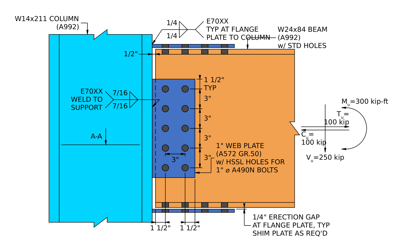
- Plaque de bride. Plates at the top and bottom flanges of the beam, shop-welded to the column and field-bolted to the beam. Alors que la poutre se plie, une plaque passe en tension et l'autre en compression, et ce couple porte le moment. A separate web plate, in effect a shear tab, carries the shear. All the welding happens in the shop, which is why fabricators like it (worked example).
- Brides soudées. The beam flanges are welded straight to the column flange with no intermediate plate, et l'âme est boulonnée à une languette de cisaillement. Cela donne le joint le plus rigide du groupe et le chemin de charge le plus propre, mais il s'agit d'un soudage sur site sur un élément qui doit s'adapter à la tolérance, donc il transporte le préchauffage, des coûts d'accès et d'inspection qu'un détail boulonné ne représente pas.
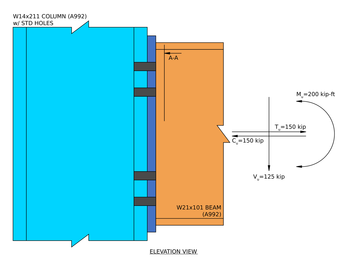
- Plaque d'extrémité affleurante. Une plaque soudée à l'extrémité de la poutre et boulonnée au poteau, finishing flush with the beam flanges so all bolts sit between them. It stays within the beam depth, which suits floors, but the bolts’ lever arm is limited, so it suits moderate moments (worked example).
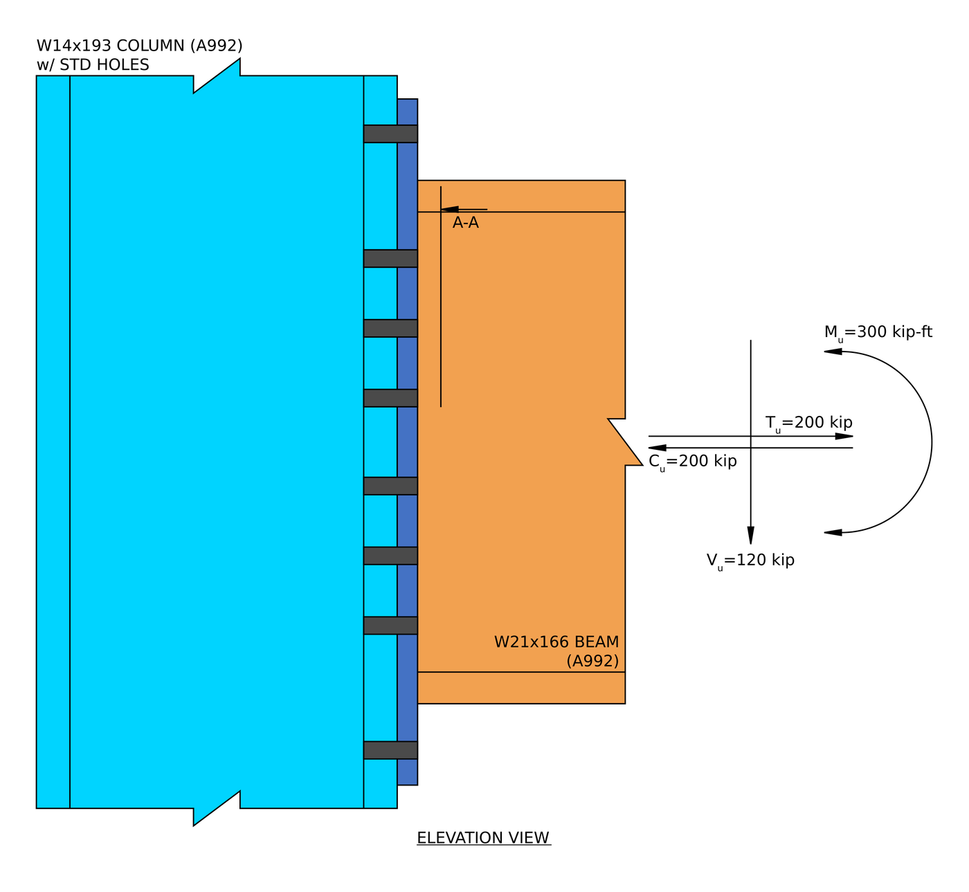
- Plaque d'extrémité étendue. La même idée, with the plate extended past the tension flange so a bolt row can sit outside it. That row has the longest lever arm about the compression flange, and the extension adds yield lines to the plate, c'est ce qui achète la capacité de moment supplémentaire. C'est la configuration affichée en haut de cette page (worked example).
Poutre vers colonne HSS (AISC 360-16)
Encadrer un assemblage de moment dans une section creuse est plus difficile, car il n'y a pas de bride à boulonner et pas d'accès au côté éloigné. Une configuration est disponible: a plaque de bride soudé à la face du HSS, sans raidisseurs.
AS 4100:2020
AS 4100 la couverture dans SkyCiv Connection Design est uniquement des connexions de cisaillement, poutre de charpente sur poteau en I ou poutre sur poutre. Connexions momentanées à AS 4100 ne sont pas disponibles. Pour le design momentané, utiliser l'AISC 360-16.
How to design a moment connection to AISC 360-16
Every moment connection is designed by following the flange force. The beam moment becomes a tension force in one flange and a compression force in the other. Each force passes from the beam flange, through the bolts, plates or welds, into the column flange, and the column has to carry it. The shear goes through the web separately. A failure anywhere along either path is a failure of the connection.
The equations below are the LRFD forms from AISC 360-16, the AISC Manual 15th Edition and, for end plates, Guide de conception AISC 39. Pour les TSA, replace [mathin] \phi R_{n} [mathin] avec [mathin] R_{n} / \Omega [mathin], en utilisant le [mathin] \Omega [mathin] given in the same clause ([mathin] \Omega = 2.00 [mathin] où [mathin] \phi = 0.75 [mathin], et [mathin] \Omega = 1.67 [mathin] où [mathin] \phi = 0.90 [mathin]).
1. The flange force
The moment is carried as a couple. Dividing it by the distance between the flange centroids gives the force in each flange, and an axial load adds half its value to each flange:
[math] P_{uf} = \frac{M_{u}}{d – t_{f}} + \frac{P_{u}}{2} [math]
In the flange plate example, a 300 kip-ft moment on a W24x84 with 100 kip of axial load gives [mathin] P_{uf} = 204.31\,kip [mathin], and every check on the flange plates is made against that one number.
End plates work the same way, but Design Guide 39 rolls the axial tension into an equivalent moment, because it pulls on the same tension bolts:
[math] M_{u,eq} = M_{u} + \frac{T_{u}}{2} \left( d – t_{f} \right) [math]
This is not a small correction. In the flush end plate example, 150 kip of tension turns a 200 kip-ft moment into 328.75 kip-ft.
2. Detailing limits (J2.2b, J3.3, J3.4, J3.5)
Avant tout contrôle de solidité, the connection has to be buildable. Bolts need a minimum spacing and edge distance, a wrench needs room to turn, and fillet welds need a minimum size for the parts they join (Table J2.4). L'espacement minimum des boulons est:
[math] s_{min} = 2\tfrac{2}{3}\, d_{b} \qquad (3\, d_{b}\ \text{preferred}) [math]
An end plate also has to be deep enough past each flange for the flange weld to fit. In the extended end plate example the bolt column spacing sits exactly on the minimum, un rapport de 1.000, which is allowed. Designers lay bolts out at the limits to keep the plate small.
3. Plaques d'extrémité: bolt size and plate thickness (Guide de conception 39)
Guide de conception 39 uses a thick plate approach. The bolts are sized to reach their tensile strength with no prying, and then the plate is made stiff enough that prying never develops. The bolt diameter comes from the lever arms [mathin] h_{i} [mathin] of the tension bolt rows about the centre of the compression flange:
[math] d_{b,reqd} = \sqrt{\frac{4\, M_{u,eq}}{\pi\, \phi\, F_{nt} \sum_{i} n_{i} h_{i}}}, \qquad \phi = 0.75 [math]
The plate’s bending strength comes from a yield line pattern around those bolts, summarised in the yield line parameter [mathin] Y_{p} [mathin] from the guide’s tables for each bolt pattern:
[math] t_{p,reqd} = \sqrt{\frac{1.10\, M_{u,eq}}{\gamma_{r}\, \phi\, F_{yp}\, Y_{p}}}, \qquad \phi = 0.90 [math]
Ce logiciel 1.10 factor keeps the plate 10% stronger than the demand, so it stays stiff and the no-prying assumption holds. [mathin] \gamma_{r} [mathin] est 1.0 for an extended plate and 0.8 for a flush plate, because a flush plate is more flexible and has to be made thicker to count as fully restrained. The extension is where the extra strength comes from: the extended example has [mathin] Y_{p} = 212.35\,in [mathin], contre 123.54 in for the flush plate.
4. Plaques à bride: slip, bearing and block shear (J3.8, J3.10, J4.3)
Flange plates are often detailed with oversized holes for fit-up, and J3.2 allows those only in slip-critical joints. The slip resistance of the bolt group is:
[math] \phi R_{n} = \phi\, \mu\, D_{u}\, h_{f}\, T_{b}\, N_{s}\, n_{b} [math]
où [mathin] \mu = 0.5 [mathin] for Class B surfaces, [mathin] D_{u} = 1.13 [mathin], [mathin] T_{b} [mathin] is the minimum bolt pretension from Table J3.1, et [mathin] h_{f} [mathin] is the filler factor, 0.85 when there may be two or more fillers. [mathin] \phi = 0.85 [mathin] for oversized holes. In the flange plate example slip is checked at 0.978.
Bolt bearing and tear-out follow J3.10 on both the plate and the beam flange:
[math] \phi r_{n} = \phi\, \min\left( 1.2\, l_{c}\, t\, F_{u},\ 2.4\, d_{b}\, t\, F_{u} \right), \qquad \phi = 0.75 [math]
and the plate and the beam flange are each checked for block shear tearing out around the bolts:
[math] \phi R_{n} = \phi \left( 0.6\, F_{u} A_{nv} + U_{bs} F_{u} A_{nt} \right) \le \phi \left( 0.6\, F_{y} A_{gv} + U_{bs} F_{u} A_{nt} \right), \qquad \phi = 0.75 [math]
Try bolt layouts in the calculateur de boulons.
5. Flange plates in tension and compression (J4.1, J4.4)
The tension plate is checked for yielding on the gross section and rupture through the holes:
[math] \phi R_{n} = \min\left( 0.90\, F_{y} A_{g},\ 0.75\, F_{u} A_{e} \right) [math]
The compression plate is a short column between the column face and the first bolt row. If it is stocky enough, J4.4 lets you skip the Chapter E buckling equations:
[math] \frac{K L}{r} \le 25 \quad \Rightarrow \quad \phi R_{n} = 0.90\, F_{y}\, A_{g} [math]
For a plate, [mathin] r = t / \sqrt{12} [mathin], so a thin plate reaches the limit quickly. Ce logiciel 1/2 in plate in the flange plate example comes in at 24.942, just under 25.
6. The beam at the bolt holes (D3, F13.1)
The holes come out of the beam’s tension flange at exactly the point of maximum moment. F13.1 checks whether they reduce the beam’s flexural strength:
[math] F_{u} A_{fn} \lt Y_{t} F_{y} A_{fg} \quad \Rightarrow \quad M_{n} = \frac{F_{u} A_{fn}}{A_{fg}}\, S_{x} [math]
[mathin] Y_{t} = 1.0 [mathin] quand [mathin] F_{y}/F_{u} \le 0.8 [mathin]. The flange force also has to get into the beam: half the beam, a tee, is treated as a tension member connected through the flange only, with shear lag reducing the net area:
[math] U = 1 – \frac{\bar{y}}{l} [math]
7. Welds and the base metal (J2.4, Manual Eq. 9-2)
The flange force crosses a weld in every one of these connections: flange plate to column, or beam flange to end plate. Loaded perpendicular to its length, a fillet weld gets the J2.4 directional increase of 1.5:
[math] \phi R_{n} = \phi\, 0.6\, F_{EXX}\, \frac{\sqrt{2}}{2}\, w\, L_{w} \left( 1 + 0.5\, \sin^{1.5}\theta \right), \qquad \phi = 0.75 [math]
The steel on either side limits how much of the weld size counts. For welds on both faces of a part of thickness t, the usable size in sixteenths is:
[math] D_{max} = \frac{ \frac{t}{2}\, F_{u} }{3.09\,kip/in} [math]
Guide de conception 39 adds a floor to the end plate flange welds: they are designed for at least 60% of the flange’s yield strength, so the weld is never the weak link even under a small moment.
[math] P_{fl} \ge 0.6\, F_{y}\, b_{f}\, t_{f} [math]
In the flush example the floor (295.2 kip) is higher than the force from the loads (191.5 kip), so the floor sizes the weld. In the flange plate example the 1/4 in weld to the column governs the whole connection at 0.998. Try sizes in the calculateur de soudure.
8. Shear through the web
The beam shear does not go through the flanges. In a flange plate connection it goes through the web plate, which is designed like a shear tab: cisaillement des boulons, bearing on the plate and the beam web, cisaillement de bloc, and shear yielding and rupture of the plate. In the flange plate example, shear rupture of the 1 in web plate governs that side at 0.943.
In an end plate, the shear goes through the web welds outside the tension zone, and the beam web often limits the weld. In the flush end plate example the 1/2 in web limits the usable weld size to 0.3287 in, less than the 3/8 in specified, and the web weld in shear governs the connection at 0.988.
9. The column: flange bending, web yielding, crippling and panel zone (J10)
The flange forces arrive at the column as concentrated loads, and the column has to carry them without local failure. These checks decide whether the column needs transverse stiffeners or a web doubler plate, and they are often cheaper to satisfy with a heavier column than with stiffeners.
Flange local bending, under the tension flange (Eq. J10-1):
[math] \phi R_{n} = \phi\, 6.25\, F_{y}\, t_{f}^{2}, \qquad \phi = 0.90 [math]
Web local yielding, with bearing length [mathin] l_{b} [mathin], away from the column end (Eq. J10-2):
[math] \phi R_{n} = \phi\, F_{y}\, t_{w} \left( 5k + l_{b} \right), \qquad \phi = 1.00 [math]
Guide de conception 39 uses 6k in place of 5k for end plates, because the force spreads through the plate before it reaches the column.
Web crippling, under the compression flange (Eq. J10-4):
[math] \phi R_{n} = \phi\, 0.80\, t_{w}^{2} \left[ 1 + 3 \left( \frac{l_{b}}{d} \right) \left( \frac{t_{w}}{t_{f}} \right)^{1.5} \right] \sqrt{\frac{E\, F_{y}\, t_{f}}{t_{w}}}\, Q_{f}, \qquad \phi = 0.75 [math]
Panel zone web shear, where the column web between the flange forces is in shear (Eq. J10-9):
[math] \phi R_{n} = \phi\, 0.60\, F_{y}\, d_{c}\, t_{w}, \qquad \phi = 0.90 [math]
For end plates, the tension bolts also bend the column flange into a yield line pattern, checked like the end plate itself:
[math] \phi M_{cf} = \phi\, F_{y}\, t_{f}^{2}\, Y_{c} \ge 1.10\, M_{u,eq} [math]
Panel zone shear governed the column in all three worked examples, à 0.461, 0.726 et 0.492. A failing panel zone needs a doubler plate, and a failing flange or web check needs stiffeners opposite the beam flange.
Moment connection design examples (AISC 360-16 LRFD)
Each example below is a full AISC calc sheet from SkyCiv Connection Design, written out step by step with every equation, substituted value and DCR.
| Exemple | Members and load | Lien | Governing check |
|---|---|---|---|
| Plaque d'extrémité affleurante | W21x101 beam to W14x211 column flange; 200 kip-ft, 125 kip shear, 150 kip axial | 1 in A572 Gr. 50 plaque d'extrémité, eight 1 in A490-N bolts | Web weld in shear, 0.988, with the end plate thickness just behind |
| Extended end plate | W21x166 beam to W14x193 column flange; 300 kip-ft, 120 kip shear, 200 kip axial | 7/8 in A572 Gr. 50 plaque d'extrémité, 3/4 in A325-N bolts in the four-wide/two-wide pattern | Flange weld, 0.931, then the plate thickness at 0.927 and bolt size at 0.923 |
| Plaque à bride | W24x84 beam to W14x211 column flange; 300 kip-ft, 250 kip shear, 100 kip axial | 1/2 in flange plates with eight 1 in A490-SC bolts each, 1 in web plate with ten 1 en A490-N | Flange plate weld to the column, 0.998, then bolt slip at 0.978 |
The pattern is worth knowing. In an end plate, the bolts and the plate are sized together and tend to finish close to each other, and the beam web often limits the welds. In a flange plate, everything on the flange side is checked against the same flange force, so the welds and the slip-critical bolts end up working equally hard. In all three, the column needed no stiffeners or doubler plate, but the panel zone was the column check closest to its limit.
For the theory behind the examples, voir design of steel connections using AISC 360-16.
Which moment connection should you use?
| Lien | Best for | Watch for |
|---|---|---|
| Plaque à bride | All shop welding, all field bolting, and erection tolerance at the flanges | Slip-critical bolts in oversized holes, shims and filler factors, and the plate weld to the column |
| Welded flanges | The stiffest joint and the shortest load path | Field welding, preheat, access and inspection |
| Plaque d'extrémité affleurante | Moderate moments where nothing can project past the beam, for example under a slab | Short bolt lever arms, l' 0.8 reduction on the plate, and the beam web limiting the welds |
| Extended end plate | Larger moments with fast, all-bolted field erection | Accurate beam length, épaisseur de la plaque, and column flange bending at the tension bolts |
Que vérifie le logiciel?
Les détails s'exécutent en premier: distances entre les bords des boulons, espacement des boulons (pas et jauge), jeux d'outils, dimensions minimales et maximales de la plaque, minimum weld sizes, et détection de collision entre plaques, raidisseurs, boulons et soudures. Une connexion qui ne peut pas être établie n’atteint pas la solution.
The strength checks then follow the procedure above. For end plates that means the required bolt diameter and plate thickness from Design Guide 39, the extended portion of the plate in shear, the flange and web welds with their base metal, and bolt shear, bearing and tear-out. For flange plates it means slip, palier, cisaillement de bloc, plate tension and compression, beam rupture at the holes and the welds, plus the web plate as a shear tab. On the column it means flange bending, rendement web local, Web paralysant, web compression buckling and panel zone shear.
Chaque formule, le contrôle de conception et la référence du code sont affichés dans leur intégralité, avec les numéros de clause de l'AISC 360-16, pour que vous puissiez suivre le calcul plutôt que de vous y fier. The worked examples above are written from those reports. For the fastener side, voir la documentation sur boulons et soudures.
Connexion de moment vs connexion de cisaillement: la différence
La différence est ce qui arrive à l'angle entre les deux membres. Dans un moment de connexion, cet angle est maintenu, donc la flexion d'un membre se répercute sur l'autre. Dans un assemblage par cisaillement, l'assemblage est libre de tourner, de sorte que l'extrémité de la poutre tourne et qu'aucun moment significatif ne traverse le joint. Voir what is a shear connection for the other half of the comparison.
| Connexion rigide | Connexion rotulé | |
|---|---|---|
| Forces transférées | Cisaillement et moment | Cisaillement seulement |
| Noms alternatifs | Rigide, Fixé, Résistant aux moments | Épinglé, Charnière, Facile |
| AISC 360-16 terme | Connexion instantanée FR ou PR | Connexion simple |
| Rotation | Restreint la rotation | Libre de tourner |
| Code de fixité du logiciel | FFFFFF | FFFFFR |
Questions fréquentes
How do you calculate the flange force in a moment connection?
Divide the beam end moment by the distance between the flange centroids, [mathin] d – t_{f} [mathin], and add half of any axial load. A 300 kip-ft moment on a W24x84 (d = 24.1 in, tF = 0.77 in) avec 100 kip of axial load gives 204.31 kip in each flange.
What is the difference between a fully restrained and a partially restrained moment connection?
A fully restrained (FR) connection holds the angle between the members, so the frame can be analysed with a fixed joint. A partially restrained (RP) connection transfers moment but rotates noticeably, so its rotational stiffness has to go into the analysis. AISC 360-16 B3.4 defines both. Ce logiciel 0.8 reduction factor on flush end plates in Design Guide 39 exists to keep those connections stiff enough to be treated as FR.
When does a moment connection need column stiffeners or a doubler plate?
When the column fails one of the J10 checks under the flange forces. Flange local bending, rendement web local, web crippling and web compression buckling are fixed with transverse stiffeners opposite the beam flanges. Panel zone shear is fixed with a doubler plate on the column web. Often a heavier column section is cheaper than either, because stiffeners and doublers add welding.
What is the difference between a flush and an extended end plate?
A flush end plate stops at the beam flanges, so all the bolts are between them. An extended end plate projects past the tension flange with a bolt row outside it. That row has the longest lever arm, and the extension adds yield lines, so an extended plate carries a much larger moment. A flush plate is used where the connection has to stay within the beam depth.
Why are flange plate bolts slip-critical?
Flange plates are usually detailed with oversized holes, to give the erector tolerance at the flanges, et AISC 360-16 J3.2 allows oversized holes only in slip-critical connections. The bolts are pretensioned and the faying surfaces prepared, typically to Class B, so the joint carries the flange force by friction.
Can I design a moment connection with ASD instead of LRFD?
Oui. The limit states are the same. Remplacer [mathin] \phi R_{n} [mathin] avec [mathin] R_{n} / \Omega [mathin] and compare against the ASD loads. SkyCiv Connection Design runs both, and switching between them is one setting.
Do the examples follow the AISC 15th or 16th edition Manual?
They follow AISC 360-16 with the AISC Manual 15th Edition, qui est écrit autour de cette spécification, et Guide de conception AISC 39 for the end plates. The 16th Edition Manual pairs with AISC 360-22. The limit states are much the same, but clause and table references move, alors vérifiez-les par rapport à l'édition utilisée par votre projet.
Logiciel de conception de connexion SkyCiv
Les modèles et chèques ci-dessus proviennent de Conception de connexion SkyCiv. Il couvre 80+ types de connexion préconfigurés, conceptions selon AISC 360-16 (LRFD & ASD) et AS 4100:2020, et montre chaque formule, vérification de la conception et référence du code dans son intégralité.
Vous pouvez modéliser la connexion en 3D, échanger les boulons, soudures ou plaques sans perdre vos données de charge, produire des feuilles de dessin de détail 2D dans CloudCAD, et exporter la géométrie 3D vers IFC pour coordination dans Revit, Tekla ou Navisworks.
Il fonctionne entièrement dans le navigateur, sans téléchargement, mises à jour ou configuration informatique.
The full module adds the step-by-step calculation report, like the worked examples above, with every capacity and DCR.
Références
- AISC 360-16, Spécification pour les bâtiments en acier de construction: B3.4, D3 (Table D3.1), F13.1 (Eq. F13-1), J2.2b (Table J2.4), J2.4, J3.1 (Table J3.1), J3.2, J3.3, J3.4, J3.5, J3.6, J3.8, J3.10, J4.1, J4.3, J4.4 (Eq. J4-6), J10 (Eq. J10-1, J10-2, J10-4, J10-8, J10-9).
- Manuel de construction en acier AISC, 15e édition: Partie 9 (Eq. 9-2, base metal limit on weld size); Partie 12 (fully restrained moment connections).
- Guide de conception AISC 39, End-Plate Moment Connections.

Harold Munalem
Chef de produit, Conception de connexion
10+ années dans la conception d'assemblages en acier
LinkedIn
