
This tutorial walks you step by step through designing a connection in the SkyCiv Connection Design module.
The design UI has five main tabs:
- Détails
- Assemblée
- Agencements
- Charges
- Résultats
Work through them in order. Each one feeds the next, and the 3D model re-renders as you go, so you can see what you are building before you solve it.
Détails
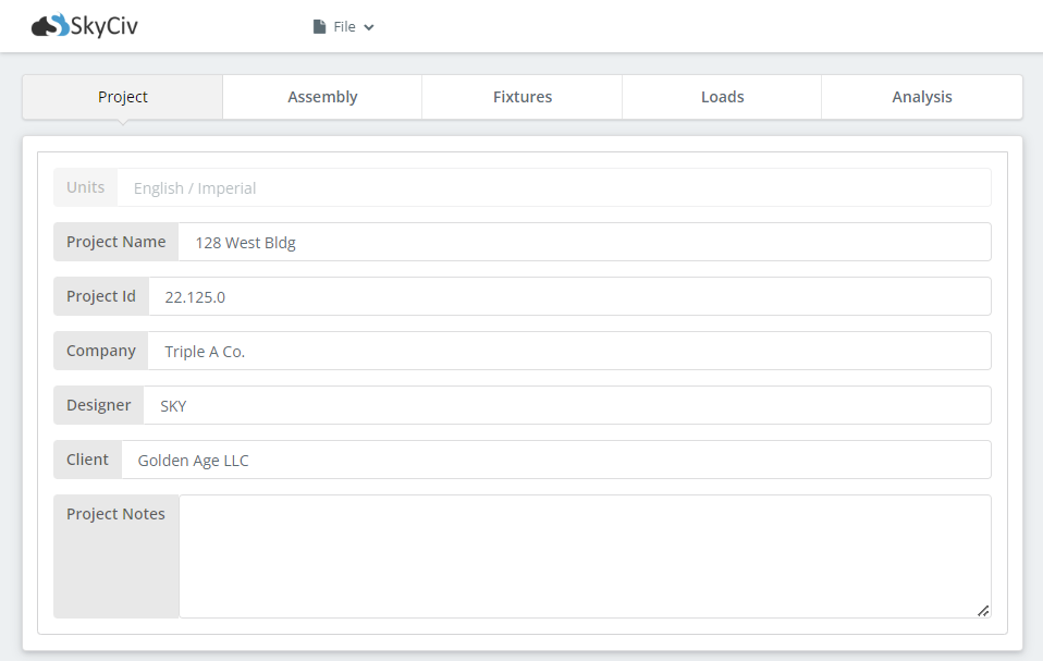
The Details tab is where you record your project information. None of it affects the calculations, but it carries through to the report, which is what makes a set of designs traceable months later:
- nom du projet
- ID de projet
- Compagnie
- Designer
- Client
- Notes de projet
Assemblée
The second tab is where you build the connection itself.
Colonne
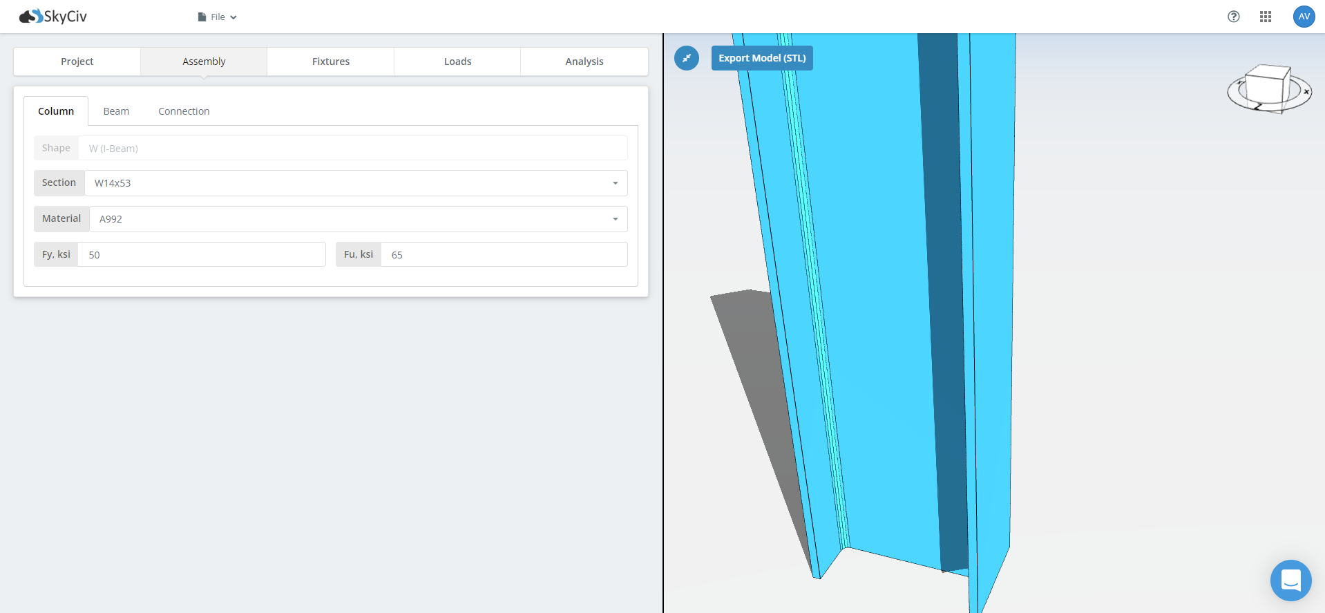
Start with the supporting member, usually a column. Pick the section size from the dropdown next to the Section label, then the material grade. The common grades are in the list; for anything else, type your own Fy and Fu into those fields. Check the units shown against each field before you type.
Beam
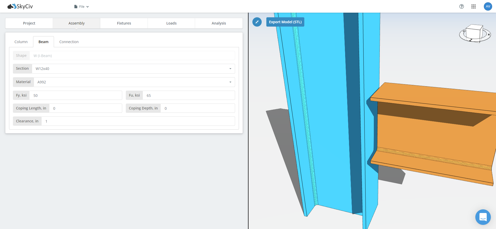
Next comes the beam. Supply its section size and material grade the same way. This tab also holds cope dimensions and beam clearance. Add a cope where the beam frames into a supporting beam of similar depth and the top flange has to be cut back, since the coped section governs a check the uncoped one does not.
Lien
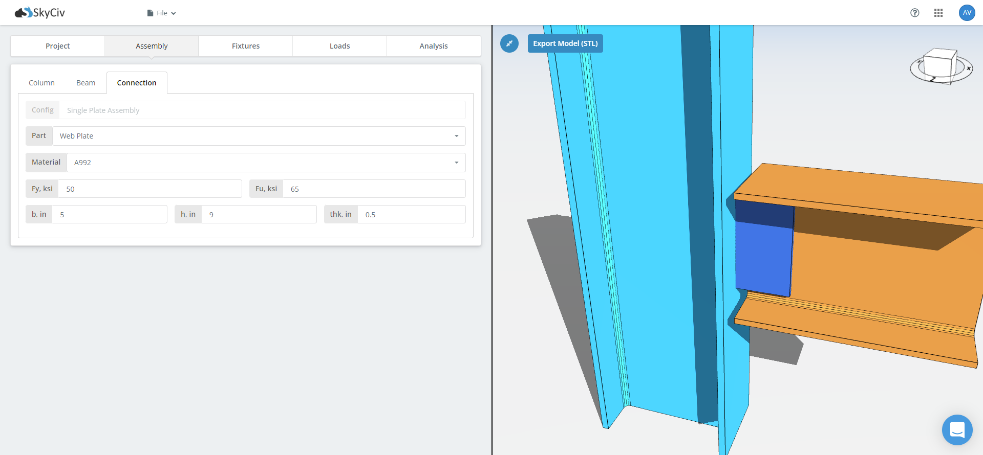
Last come the connecting components: notes, épaisseurs, widths and lengths for the plates or angles. Where a connection has both a flange and a web component, remember to switch between the two sub-tabs and fill out each one. A moment connection typically carries the moment through the flanges and the shear through a separate web plate, so both need setting up.
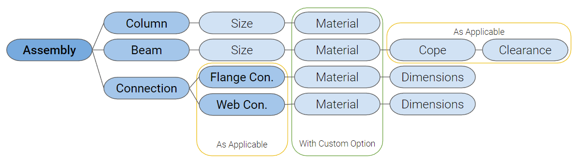
Once the fields are filled for each tab, the model renders the 3D figure automatically. You can try this in the free tool without an account.
Agencements
The Fixtures tab holds the sub-groups of fixtures, numbered, with a short description under each tab name.
Start by choosing the fixture type. Il y en a deux: bolted and welded. On some connections the type is pre-selected and locked, because the configuration only works one way. If the type you want is not available, envoyer une demande de fonctionnalité à l'équipe d'assistance de SkyCiv.
Verrouiller
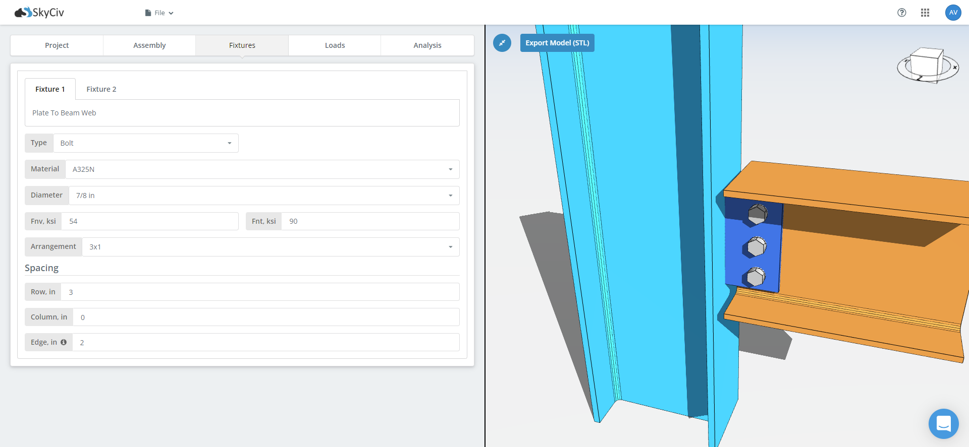
For a bolted fixture you supply:
- Matériau
- Diamètre
- Résistance au cisaillement et à la traction des boulons
- Hole type
- Arrangement
- Écartement des rangs
- Espacement des colonnes
- Distance du bord
Most of these are dropdowns, and there is a tooltip on Edge Distance explaining what it measures from.
Once the required fields are filled, the bolts render in the model. Change the bolt size or open up the spacing and the connection updates as you watch, which is the quickest way to find out whether a bolt group actually fits before the detailing checks tell you it does not.
Souder
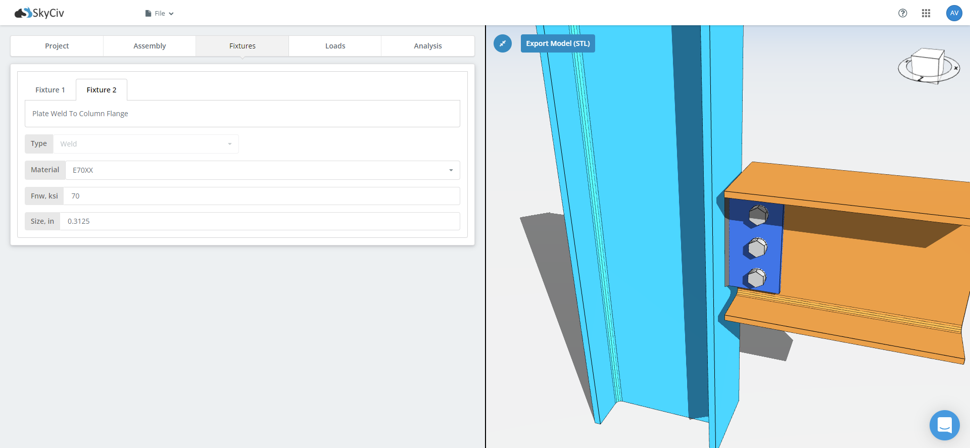
A weld fixture takes fewer inputs than a bolted one:
- Matériau
- Force de soudure
- Taille
The 3D model updates once the weld fixture is set.
For more on what the module does with these, voir la documentation sur boulons et soudures.
Charges
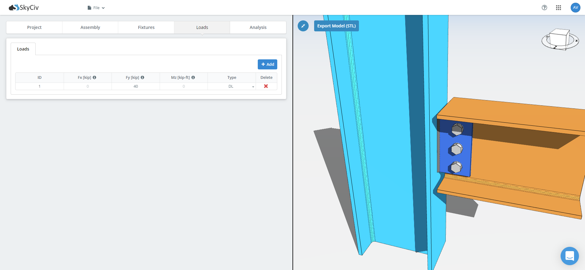
Type the design loads straight into the cells of the loads table. Which columns you get depends on the connection type: a shear connection takes shear alone, a moment connection takes axial, cisaillement et moment, and a brace connection takes axial.
Match your loads to the design method you chose. Under LRFD, enter factored loads and the module compares them against design strength. Under ASD, enter service loads and it compares them against allowable strength. Entering factored loads into an ASD design, or service loads into an LRFD one, gives you a utilization ratio that means nothing, and the software cannot tell which you typed.
Résultats
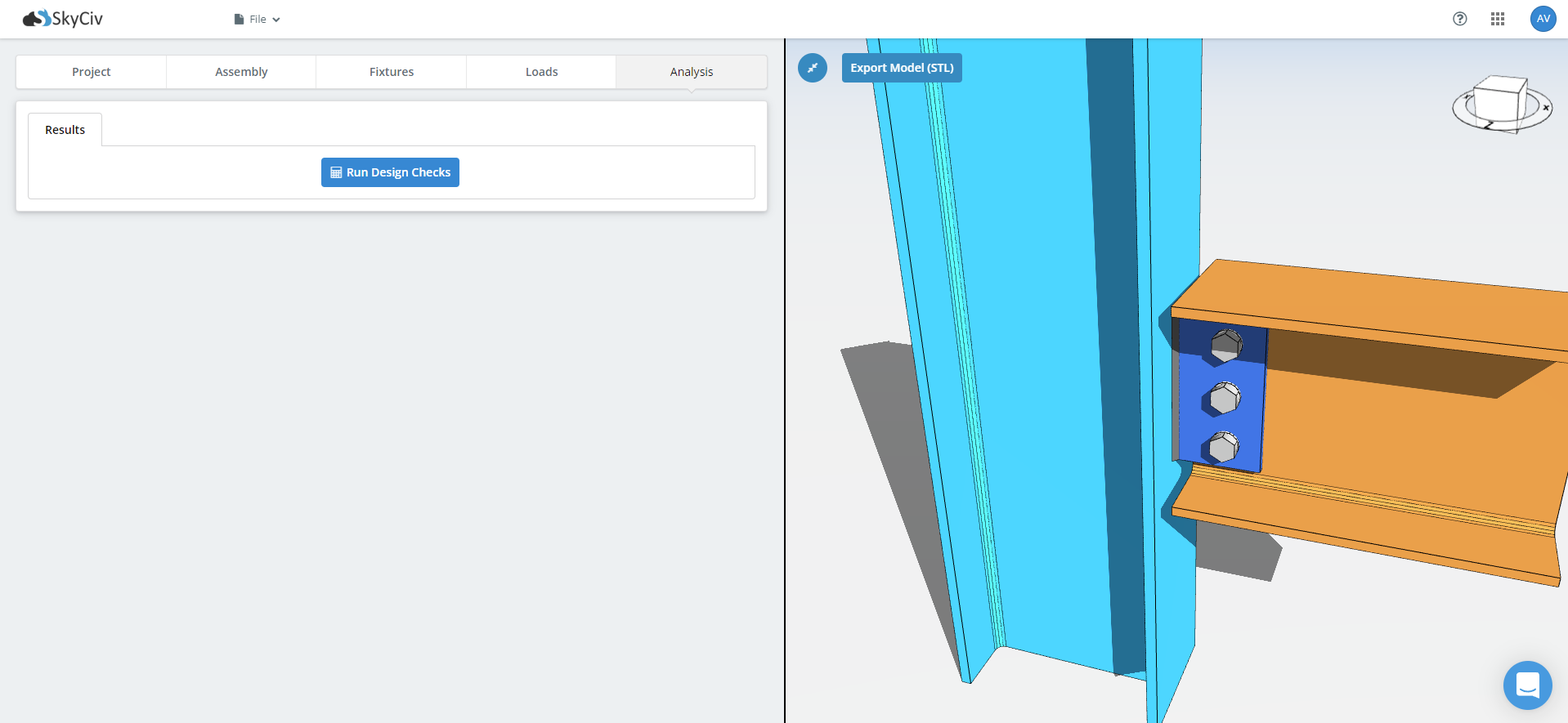
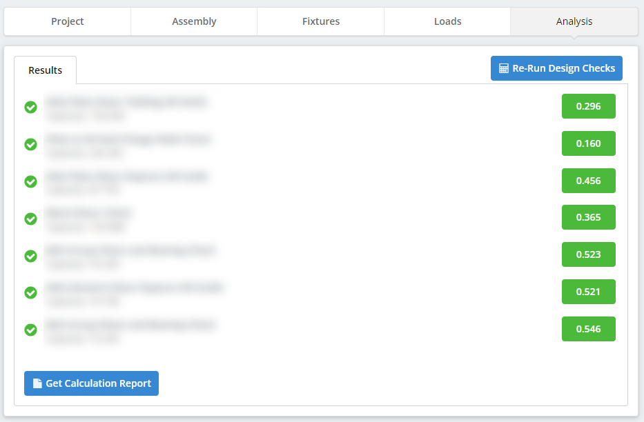
With everything supplied, run the design checks. Results come back as a table and as graphics, with a utilization ratio and a pass or fail against each check, and the governing check called out at the top.
Detailing runs before the strength checks: distances entre les bords des boulons, espacement, jeux d'outils, dimensions de la plaque, et détection de collision entre plaques, raidisseurs, boulons et soudures. A connection that cannot be built fails here, before any capacity is calculated, which is usually what you want.
Depuis cet onglet, Afficher le rapport de calcul opens the step-by-step calculations with every formula and clause reference, and Download PDF or Download HTML saves it. View Detailed Drawing opens the CloudCAD 2D detail sheet, with plan and elevation views, légendes de soudure, nomenclatures et dimensions des boulons, which you can edit in-app and export.
Commencez aujourd'hui
Ready to try it? Choisissez une connexion, entrez vos sections et vos chargements, et voir chaque chèque. Il s'exécute dans le navigateur, with nothing to install and no account needed to start.
Conception de connexion SkyCiv
Conception de connexion SkyCiv covers over 80+ types de connexion préconfigurés, conceptions selon AISC 360-16 in LRFD and ASD and to AS 4100:2020, and shows every formula and code reference in full. Un compte gratuit vous permet de sauvegarder et de recharger vos fichiers de connexion.
Conception de connexion autonome
Vous souhaitez utiliser uniquement le module de conception de connexion? Cliquez sur le bouton ci-dessous pour le prix autonome.
