Conception à pile unique selon AS 2159 (2009) & 3600 (2018)
En cas de charge latérale élevée ou de conditions de sol défavorables, les fondations sur pieux sont plus préférées aux fondations peu profondes. Des tentatives telles que les méthodes de modification du sol peuvent être faites pour éviter les tas, toutefois, ces méthodes peuvent impliquer des processus coûteux, dans lequel ce cas, des piles peut-être encore moins cher.
Le module SkyCiv Foundation Design comprend la conception de pieux conformes à l'American Concrete Institute (ACI 318) et normes australiennes (AS 2159 & 3600).
SkyCiv exemple-de-rapport-concret facilite l'application d'AS 2159 et 3600 contrôles dans les projets structurels.
Vous voulez essayer le logiciel Foundation Design de SkyCiv? Notre outil gratuit permet aux utilisateurs d'effectuer des calculs de charge sans aucun téléchargement ni installation!
Conception de la résistance géotechnique d'un pieu
Les charges verticales appliquées sur les pieux sont portées par l'appui d'extrémité du pieu et la peau ou le frottement de l'arbre sur sa longueur. La résistance géotechnique de conception (Rd,g) est égal à la résistance géotechnique ultime (Rd,et) multiplié par un facteur de réduction géotechnique (øg) comme spécifié sur AS 2159 Section 4.3.1.
\({R}_{d,g} = {ø}_{g} × {R}_{d,et}\) (1)
Rd,g = Résistance géotechnique de conception
Rd,et = Résistance géotechnique ultime
øg = Facteur de réduction géotechnique
Résistance géotechnique ultime (Rd,et)
La résistance géotechnique ultime est égale à la somme du frottement superficiel pondéré du pieu (Fm,s ) multiplié par la surface latérale et la résistance de base multiplié par la section transversale à la pointe du pieu.
\( {R}_{d,et} = [{R}_{s} × ({F}_{m,s} × {A}_{s} )] + ({F}_{b} × {A}_{b} )\) (2)
Rs = Facteur de réduction pour la résistance de l'arbre
Fm,s = Résistance de frottement de l'arbre
As = Surface latérale
Fb = Terme de résistance de base
Ab = Aire de la section transversale à la pointe du pieu
Pour un guide plus détaillé, consultez notre article sur le calcul la résistance au frottement cutané et la capacité portante en bout.
Facteur de réduction géotechnique (øg)
Le facteur de réduction géotechnique est un calcul basé sur le risque pour la conception finale qui prend en compte différents facteurs, comme les conditions du site, conception de pile, et facteurs d'installation. Sa valeur varie généralement de 0.40 à 0.90. AS 2159 4.3.1 indique également comment estimer sa valeur comme indiqué dans l'équation (3).
\( {ø}_{g} = {ø}_{Go} + [K × ({ø}_{tf} – {ø}_{Go})] ≥ {ø}_{Go} \) (3)
øGo = Facteur de réduction de résistance géotechnique de base
øtf = Facteur de test intrinsèque
K= Facteur de bénéfice du test
Les facteurs intrinsèques de test et d'avantage de test dépendent tous deux du type de test de charge utilisé sur les pieux. Leurs valeurs sont spécifiées dans le tableau 1 et sur les équations (4) et (5). Les tests de charge de pieux sont brièvement abordés dans la section 8 d'AS 2159.
| Facteur de test intrinsèque (øtf) | |||||||||||||
|---|---|---|---|---|---|---|---|---|---|---|---|---|---|
| Test de charge statique | 0.90 | ||||||||||||
| Test de charge rapide | 0.75 | ||||||||||||
| Essai de charge dynamique des pieux préformés | 0.80 | ||||||||||||
| Essais de chargement dynamique de pieux autres que préformés | 0.75 | ||||||||||||
| Test de charge bidirectionnel | 0.85 | ||||||||||||
| Pas de test | 0.80 | ||||||||||||
Le tableau 1: Valeurs des facteurs de test intrinsèques
Facteur d'avantage de test pour les tests de charge statique:
\( K = frac{1.33 ×p}{p + 3.3} ≤ 1\) (4)
Facteur d'avantage de test pour les tests de charge dynamique:
\( K = frac{1.13 ×p}{p + 3.3} ≤ 1\) (5)
p = Pourcentage du nombre total de pieux qui sont testés et répondent aux critères d'acceptation
Le facteur de réduction de la résistance géotechnique de base est évalué à l'aide d'une procédure d'évaluation des risques décrite dans la section 4.3. d'AS 2159. Le résultat de ladite procédure est la notation individuelle des risques (TRI) et une conception globale Note de risque moyenne (ARR) qui doit être utilisé pour déterminer la valeur de øGo comme indiqué dans le tableau 2.
| Facteur de réduction de résistance géotechnique de base (øGo) | |||||||||||||
|---|---|---|---|---|---|---|---|---|---|---|---|---|---|
| Cote de risque moyenne (ARR) | Catégorie de risque | øGo pour les systèmes à faible redondance | øGo pour les systèmes à haute redondance | ||||||||||
| ARR ≤ 1.5 | Très lent | 0.67 | 0.76 | ||||||||||
| 1.5 < ARR ≤ 2.0 | Très faible à faible | 0.61 | 0.70 | ||||||||||
| 2.0 < ARR ≤ 2.5 | Faible | 0.56 | 0.64 | ||||||||||
| 2.5 < ARR ≤ 3.0 | Faible à modéré | 0.52 | 0.60 | ||||||||||
| 3.0 < ARR ≤ 3.5 | Modérer | 0.48 | 0.56 | ||||||||||
| 3.5 < ARR ≤ 4.0 | Modéré à élevé | 0.45 | 0.53 | ||||||||||
| 4.0 < ARR ≤ 4.5 | Haute | 0.42 | 0.50 | ||||||||||
| ARR > 4.5 | Très haut | 0.40 | 0.47 | ||||||||||
Le tableau 2: Valeurs du facteur de réduction géotechnique de base, (AS 2159 Le tableau 4.3.2)
Les systèmes à faible redondance sont des pieux isolés fortement chargés tandis que les systèmes à forte redondance comprennent de grands groupes de pieux sous de grands chapeaux de pieux ou des groupes de pieux avec plus de 4 pieux.
Résistance structurelle de conception
Les pieux sont structurellement conçus presque de la même manière qu'une colonne. Résistance structurelle de conception (Rd,s) nécessite des capacités ultimes, telles que les forces axiales et de cisaillement, et moment de flexion. La résistance structurale de conception d'un pieu en béton est équivalente à la résistance de conception ultime (Rnous) réduit par un facteur de réduction de résistance (øs) et un facteur de placement concret (k), comme indiqué par la section 5.2.1 d'AS 2159.
\( {R}_{d,s} = {ø}_{s} × k × {R}_{nous} \) (6)
øs = Facteur de réduction de résistance
k = facteur de mise en place du béton
Rnous = Force de conception ultime
Les valeurs du facteur de réduction de résistance sont indiquées dans le tableau 3. Le facteur de mise en place du béton varie de 0.75 à 1.0, selon la méthode de construction des pieux. Par contre, pour pieux autres que béton et coulis, k doit être pris comme 1.0.
| Facteurs de réduction de la force (ø) | |||||||||||||
|---|---|---|---|---|---|---|---|---|---|---|---|---|---|
| Force axiale sans flexion | 0.65 | ||||||||||||
| Flexion sans force axiale (øpb) | 0.65 ≤ 1.24 – [(13 ×keuh)/12] ≤ 0.85 | ||||||||||||
| Flexion avec compression axiale: | |||||||||||||
| (je) Nu ≥Neuh | 0.60 | ||||||||||||
| (ii) Nu < Neuh | 0.60 + {(øpb – 0.66) × [1 – (Nu/Neuh)]} | ||||||||||||
| Tondre | 0.70 | ||||||||||||
Le tableau 3: Facteurs de réduction de résistance (Le tableau 2.2.2, AS 3600-18)
Capacités axiales et flexibles d'un seul pieu
Similaire aux colonnes, les pieux peuvent également être soumis à une charge combinée de compression et de flexion. Les capacités axiales et en flexion sont vérifiées à l'aide d'un diagramme d'interaction. Ce diagramme est une représentation visuelle du comportement des capacités de flexion et axiales causées par une augmentation de la charge du point de flexion pur jusqu'à ce qu'un point d'équilibre soit atteint.
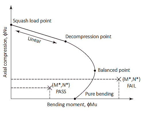
Figure 1: Diagramme d'interaction de colonne
Charge d'écrasement (Neuh)
Le point de charge de squash est un point sur le diagramme où le pieu se rompra en compression pure. À ce point, la charge axiale est appliquée sur le centroïde plastique de la section pour rester en compression sans flexion. Charge de courge (Neuh) et l'emplacement du centre de gravité plastique (dq) sont calculés comme indiqué dans les équations (7) & (8). Bien que l'emplacement du centre de gravité plastique puisse être considéré comme 1/2 de la profondeur totale de la section transversale pour les sections symétriques avec une disposition symétrique des armatures.
\( {N}_{euh} = ø × [({A}_{g} – {A}_{s}) × ({une}_{1} × f’c) + ({A}_{s} × {F}_{le sien})] \) (7)
Ag = Superficie de la section transversale brute
As = Superficie totale de l'acier
une1 = 1.0 – (0.003 × f’c) [0.72 ≤α1 ≤0,85]
f'c = Résistance du béton
Fle sien = Limite d'élasticité de l'acier
\( {d}_{q} = frac{[(b × D) – {A}_{s}] × ({une}_{1} × f’c) × somme_{je=1}^{n} ({A}_{bi} × {F}_{le sien} × {d}_{en fonction de la valeur de la barre de déformation})}{{N}_{euh}} \) (8)
b = largeur de la section transversale du pieu
D = Profondeur ou diamètre de la section transversale du pieu
Abi = Zone de la barre d'armature considérée
den fonction de la valeur de la barre de déformation = Profondeur de la barre d'armature considérée
Écraser le point de charge jusqu'au point de décompression
Le point de décompression est l'endroit où la déformation du béton à la fibre de compression extrême est égale à 0.003 et la déformation dans la fibre de traction extrême est nulle. La résistance du pieu entre la charge d'écrasement et les points de décompression peut être calculée par interpolation linéaire avec facteur de réduction de résistance (øs) de 0.6.
Point de décompression jusqu'à la flexion pure
Le point de flexion pur est l'endroit où la capacité de charge axiale est nulle. La transition du point de décompression à la flexion pure utilise un facteur de réduction de résistance de 0.6 à 0.8 et un paramètre d'entrée (ku) est introduit. La valeur de ku commence à 1 au point de décompression et diminue jusqu'à atteindre la flexion pure. Entre la transition des deux points, une condition équilibrée est atteinte. À ce point, la déformation du béton est à sa limite (ec= 0,003) et la déformation extérieure de l'acier atteint le rendement (es= 0,0025), La valeur de ku à ce stade est d'environ 0.54 avec un facteur de réduction de résistance de 0.6.
Une fois une valeur de ku est sélectionné, les forces de traction et de compression de la section peuvent être calculées. La charge axiale sur la section est équivalente à la somme des forces de traction et de compression, tandis que le moment de flexion est calculé en résolvant ces forces autour de l'axe neutre. Le calcul des forces de compression et de traction est énuméré ci-dessous
Force due au béton (Fcc):
\( {F}_{cc} = {une}_{2} × f'c × {A}_{c} \) (9)
une2 = 0.85 – (0.0015 × f’c) [une2 ≥0.67]
Ac = Zone de bloc de compression (reportez-vous à la figure 2)
= b × c × ku × d (section rectangulaire)
=(1/2) × (θ – sinθ) × (J/2)2 (Section transversale circulaire)
γ = 0.97 – (0.0025 × f’c) [c ≥0.67]
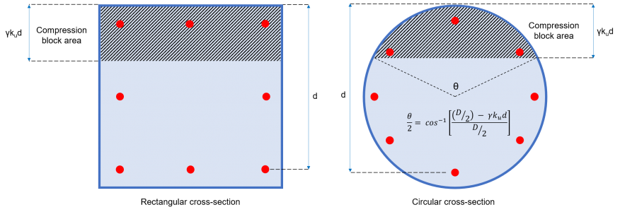
Figure 2: Zone de blocs de compression en béton
Obliger (Fet) et moment (Mje) contribué par chaque bar individuel:
Chaque armature du profilé exerce un effort qui peut être soit en compression, soit en traction, en fonction de la valeur de la barre de déformation (eet) en fonction de la valeur de la barre de déformation (10).
\( {e}_{et} = frac{{e}_{c}}{({k}_{u} × d)} × [({k}_{u} × d) – {d}_{en fonction de la valeur de la barre de déformation}] \) (10)
den fonction de la valeur de la barre de déformation = Profondeur de la barre considérée
ec= Déformation du béton = 0.003
Si eet < 0 (en fonction de la valeur de la barre de déformation)
Si eet > 0 (en fonction de la valeur de la barre de déformation)
en fonction de la valeur de la barre de déformation:
\( {F}_{et} = {σ}_{et} × {A}_{bi} \) (11)
σet = Contrainte en bar = Le minimum [(eet × Es ), Fle sien]
Es = Module d'élasticité de l'acier
Abi = Espace bar
Barre en tension:
\( {F}_{et} = [{σ}_{et} – ({une}_{2} × f’c)] × {A}_{bi} ≥ 0\) (12)
σet = Contrainte en bar = Le minimum [(eet × Es ), –Fle sien]
Es = Module d'élasticité de l'acier
Abi = Espace bar
Moment par chaque barre:
\( {M}_{je} = {F}_{et} × {d}_{en fonction de la valeur de la barre de déformation} \) (13)
Capacité axiale du pieu:
\( {l'Ile}_{u} = ø × [ {F}_{cc} + {Σ}_{je=1}^{n} {F}_{et}]\) (14)
Capacité de flexion du pieu:
\( {douloureux}_{u} = ø × [ ({N}_{u} × {d}_{q}) – ({F}_{cc} × {Y}_{c}) – {Σ}_{je=1}^{n} {M}_{je}] \) (15)
Moment de flexion de conception:
Section 7.2 spécifie que les pieux doivent avoir une tolérance hors position de 75 mm pour le positionnement horizontal des pieux. Cette exigence peut induire un moment de flexion égal à la charge axiale multipliée par l'excentricité de 75 mm. Aussi, un moment de calcul minimal doit également être considéré, qui est équivalent à la force axiale multipliée par 5% de la largeur minimale globale du pieu. Par conséquent, le moment de flexion de calcul doit être la plus grande valeur entre les équations 16a et 16b.
\( {M}_{d} = {{M}^{*}}_{appliqué} + ({N}^{*} × 0.075 m) \) (16a)
\( {M}_{d} = {N}^{*} × (0.05 × D) \) (16b)
Md = Moment de flexion de calcul
M*appliqué = Moment appliqué
N* = Charge axiale
D = largeur de pile
Capacité de cisaillement d'un seul pieu
Le calcul de la résistance au cisaillement doit être conforme à la section 8.2 d'AS 3600. La résistance au cisaillement est équivalente aux capacités de cisaillement combinées du béton et de l'armature en acier (équation 17).
\( {øV}_{u} = ø × ({V}_{uc} + {V}_{nous}) ≤ {øV}_{u,max} \) (17)
Résistance au cisaillement du béton (Vuc)
La contribution du béton à la capacité de cisaillement est calculée comme indiqué sur l'équation (18) qui est défini sur la section 8.2.4.1 d'AS 3600. Cette section exige également que la valeur de √f'c ne dépasse pas 9.0 MPa. Les valeurs du paramètre kv et θv sont déterminés en utilisant une méthode simplifiée suggérée par la section 8.2.4.3 d'AS 3600.
\( {V}_{uc} = {k}_{v} × b × {d}_{v} × sqrt{f’c} \) (18)
dv = Profondeur de cisaillement efficace = Maximum [(0.72 × D ), (0.90 × d )]
Détermination de la surface minimale des armatures de cisaillement (Asv.min) & kv:
La surface de l'armature de cisaillement (Asv) est la surface totale des barres de toutes les barres d'acier fournies attachées dans la même direction que la charge appliquée. Section 8.2.1.7 d'AS 3600 a fourni l'équation pour les armatures de cisaillement transversal minimum, qui sera:
\( \frac{{A}_{sv.min}}{s} = frac{0.08 × sqrt{f’c} × b}{{F}_{et f}} \)
Fet f = Limite d'élasticité des barres d'armature en cisaillement
s= Espacement centre à centre des barres d'armature de cisaillement
Pour (Asv/s) < (Asv.min/s):
\( {k}_{v} = frac{200}{[1000 + (1.3 × {d}_{v} )]} ≤ 0.10\)
Pour (Asv/s) ≥ (Asv.min/s):
\( {k}_{v} = 0.15 \)
Résistance au cisaillement des barres d'acier (Vnous)
La contribution des armatures de cisaillement transversal à la capacité de cisaillement calculée est indiquée dans l'équation (19), qui est défini dans la section 8.2.5 d'AS 3600.
\( {V}_{nous} = frac{{A}_{sv} × {F}_{et f} × {d}_{v}}{s} × lit bébé{θ}_{v} \) (19)
θv= angle d'inclinaison de l'entretoise de compression = 36º
Résistance maximale au cisaillement (Vu.max)
La capacité de cisaillement est limitée et ne doit en aucun cas dépasser la valeur maximale spécifiée à la section 8.2.6 d'AS 3600 (équation 20).
\( {V}_{u.max} = 0.55 × [ (f'c × b × {d}_{v}) × frac{lit bébé{θ}_{v} + lit bébé{une}_{v}}{1 + lit bébé ^{2}{θ}_{v} }] \) (20)
unev= angle entre l'armature de cisaillement inclinée et l'armature de traction longitudinale≈ 90º
Résistance ultime au cisaillement (Vu)
La résistance totale au cisaillement apportée par le béton et les armatures de cisaillement doit être inférieure ou égale à la valeur limite de Vu.max
\( {V}_{u} = ({V}_{uc} + {V}_{nous} ) ≤ {V}_{u.max} \) (21)
Résistance au cisaillement de conception (øVu)
Le facteur de réduction de capacité qui doit être appliqué pour la résistance ultime au cisaillement est ø = 0.7. Par conséquent, la résistance de calcul au cisaillement du pieu est donnée par:
\( {øV}_{u} = ø × ({V}_{uc} + {V}_{nous} ) \) (22)
Références
- Paquet, Lonnie (2018). Guide australien pour les ingénieurs en structure. Presse du CRC.
- Conception et installation de pilotis (2009). AS 2159. Norme australienne
- Structures en Béton (2018). AS 3600. Norme australienne