Béton armé (RC) Manuel de conception (AS 3600, EN 2, ACI 318)
Détails
Une fois que l'utilisateur a choisi le code de conception souhaité, Options de données supplémentaires Ce formulaire de données supplémentaires contient tous les paramètres à utiliser pour analyser une certaine “Détails” onglet comme le montre la figure ci-dessous. Les unités seront choisies automatiquement par programme en fonction du code de conception choisi (Options de données supplémentaires Ce formulaire de données supplémentaires contient tous les paramètres à utiliser pour analyser une certaine 2 – Options de données supplémentaires Ce formulaire de données supplémentaires contient tous les paramètres à utiliser pour analyser une certaine 318 – Options de données supplémentaires Ce formulaire de données supplémentaires contient tous les paramètres à utiliser pour analyser une certaine).
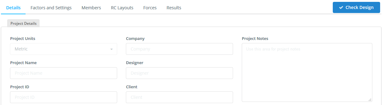
- Un nom de projet;
- Un identifiant de projet;
- Le nom de votre société;
- Le designer;
- Le client; et
- Toute autre note que vous souhaitez inclure
Ces informations seront insérées dans le rapport de conception généré.
Facteurs et paramètres
- Supposons la profondeur de l'axe neutre, X (valeur initiale d – profondeur effective)
- Calculer la force de compression du béton, force de tension et de compression de l'acier
- Vérifier l'équilibre des composantes de force
- La procédure ci-dessus sera répétée tant que la somme des forces de compression n'est pas égale aux forces de traction.
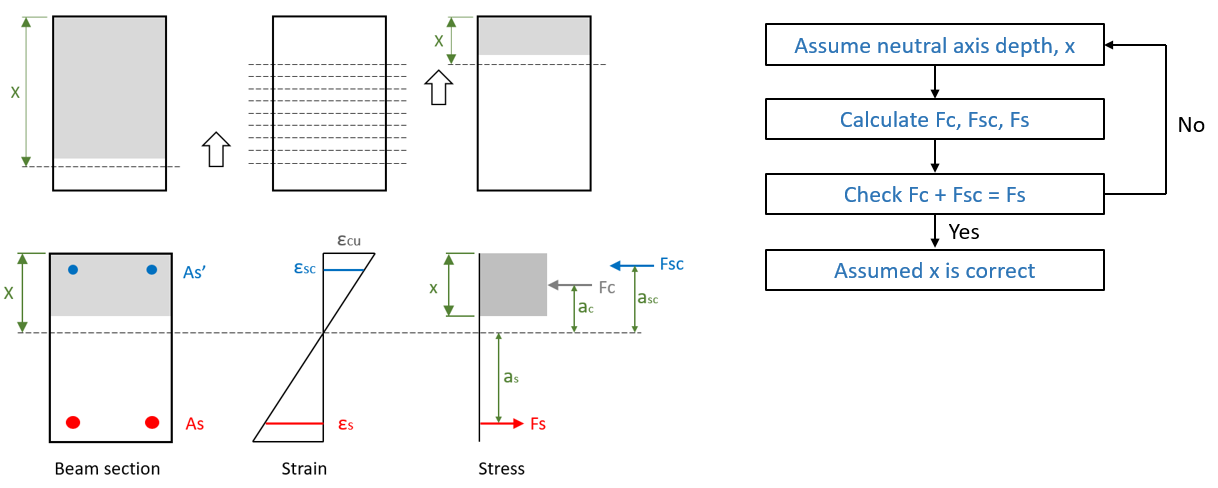
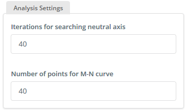
Aussi, la procédure itérative est utilisée pour le calcul de la profondeur de l'axe neutre en cas d'état limite de service, où la forme triangulaire du béton comprimé est utilisée. En général 40 les itérations suffisent. La flexion ultime est calculée comme Multime =Fc ∙ ac + Fcs ∙ acs + Fs ∙ as. Des informations détaillées sur les calculs sont décrites dans le rapport de conception de sortie.
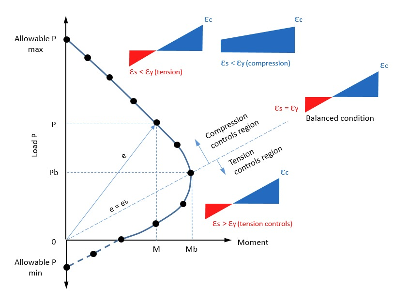
Lorsque l'utilisateur doit s'occuper de la conception des membres de la colonne, en cas d'action d'une force axiale avec flexion, le module de conception considère la courbe d'interaction N-M. Pour considérer cette courbe en interne, le programme a besoin du nombre nécessaire de points intermédiaires. Il y a généralement trois points principaux: tension axiale maximale, compression axiale maximale et condition équilibrée. Ensuite, les points intermédiaires sont considérés de l'état d'équilibre à la tension maximale et de l'état d'équilibre à la compression maximale.. Par défaut, le programme considère 40 points, bien que l'utilisateur ait la liberté de modifier ceci.
Dans le cas d'une force axiale avec flexion biaxiale, le programme considère les surfaces d'interaction 3D N-Mx-My basées sur “Méthode de contour de charge de Bresler”. Le programme considère un ensemble de courbes M-N séparément, puis, par la méthode du contour de charge, génère des surfaces 3D.. Des informations détaillées sur ces calculs sont décrites dans le rapport de conception de sortie.
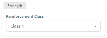
Dans le cas de l'AS 3600 code de conception, la classe de ferraillage doit être sélectionnée. Cela sera reflété dans le calcul du facteur de réduction de résistance φ
Membrures
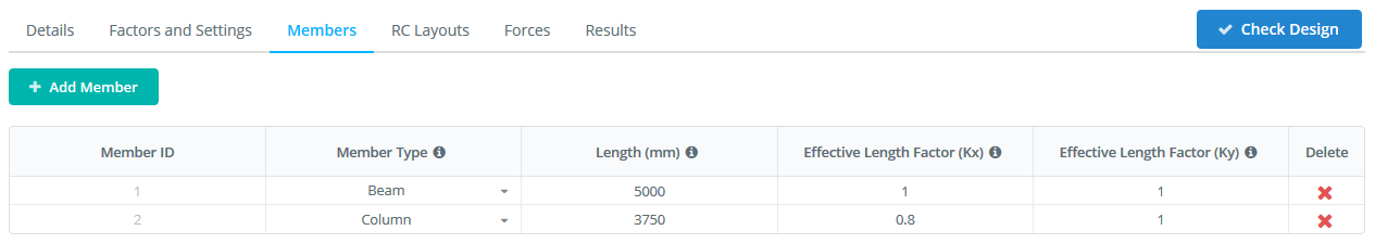
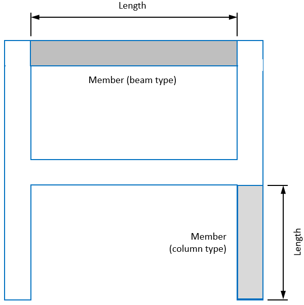
Dans le module autonome, l'utilisateur peut définir le nombre de membres souhaité, qui peut être établi avec un type de poutre ou de colonne. Pour chaque barre, la longueur libre doit être définie. Si le membre est un type de colonne, une entrée supplémentaire est nécessaire pour la longueur efficace.
Dans le logiciel SkyCiv Beam, où seuls les éléments de type poutre sont pris en compte, l'utilisateur doit entrer le coefficient de déflexion typique. Ce coefficient sera utilisé pour le calcul de la flèche de la poutre avec ouverture de fissure en section.
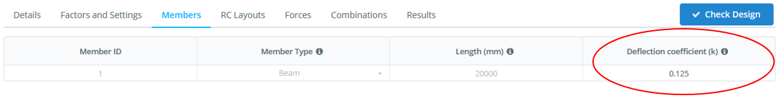
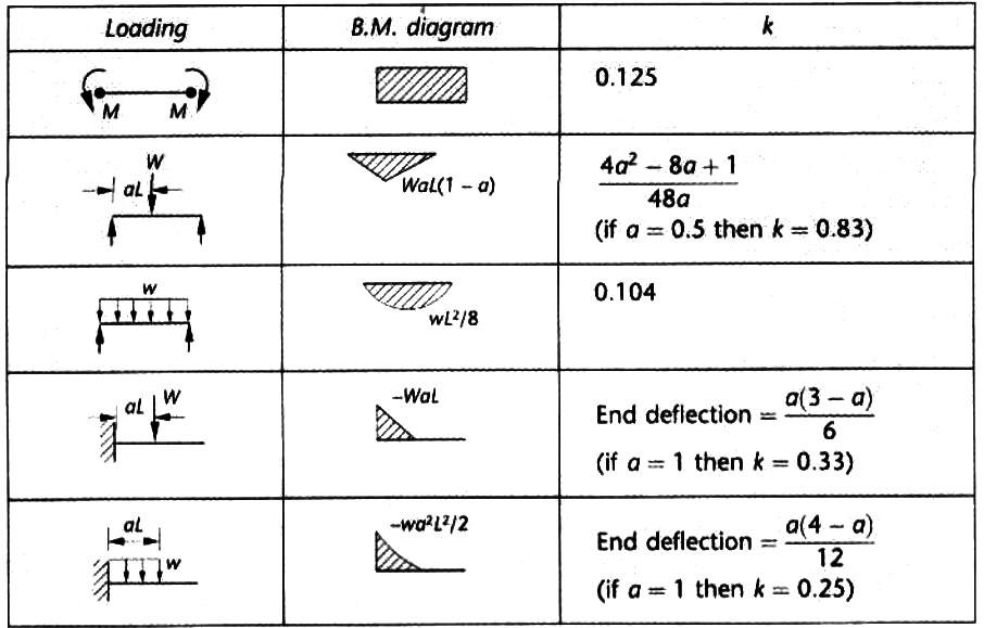
Vous trouverez ci-dessous quelques exemples de coefficients de déflexion typiques qui représentent différents cas de flexion de poutre..
lancer le module de conception
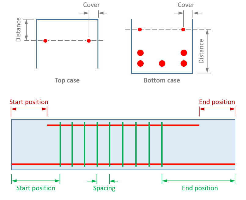
Pour chaque élément à concevoir, le type de section, propriétés des matériaux et renforcement, doit être défini. Pour la rubrique, le type de section doit être choisi et ses dimensions définies. Pour les renforts, le renfort longitudinal et de cisaillement (étriers) doit être défini. L'utilisateur peut disposer les barres d'armature dans n'importe quelle position longitudinale et transversale à l'intérieur de l'élément.. Si le ferraillage de cisaillement n'est pas défini lors du contrôle de conception de la section, le programme prendra en compte la capacité de cisaillement avec uniquement un renforcement longitudinal. dernièrement, les propriétés de résistance des matériaux pour le béton et l'acier, ainsi qu'une largeur de fissure limitée, doit être défini.
Une fois toutes les données définies pour le membre, l'utilisateur doit procéder pour enregistrer la configuration en cliquant sur le “sauver” bouton. Ceci est nécessaire pour que la disposition RC soit appliquée, autrement, ils ne seront pas enregistrés pour le contrôle de conception.
Les forces
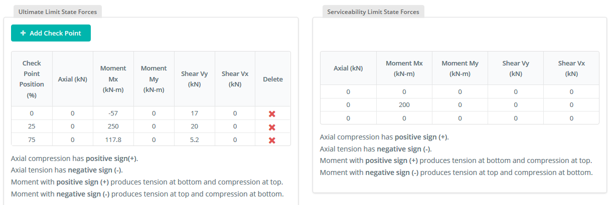
Pour la version autonome de ce module, les forces sont définies manuellement dans des tableaux. Ci-dessous deux tableaux: l'un concerne les forces qui seront prises en compte pour les contrôles à l'état limite ultime et l'autre pour les contrôles à l'état limite de service.. Les forces sont définies pour chaque section de la barre et le nombre de sections le long de la barre n'est pas limité.. En cliquant sur le “Ajouter un nouveau point” Le bouton permet à l'utilisateur de définir la position (as a % de longueur le long du membre) et l'ensemble des forces agissant à cet endroit le long du membre.
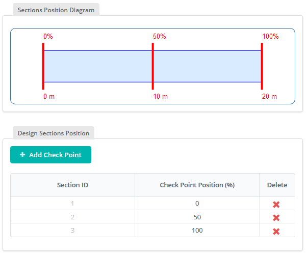
Dans le faisceau SkyCiv, les efforts sont définis automatiquement en fonction de l'analyse des poutres effectuée par le module. Dans le cas présent, l'utilisateur peut simplement définir le nombre souhaité de sections à concevoir et spécifier leurs positions le long de la barre.
de charges
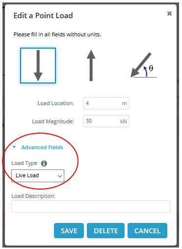
Si l'utilisateur souhaite considérer des combinaisons de charges, il doit définir le type de charge pour chaque charge appliquée au modèle de poutre.
Dans l'onglet Combinaisons, l'utilisateur peut définir toutes les combinaisons de charges nécessaires pour les contrôles de résistance et de fonctionnement. Par défaut, le programme génère un ensemble de combinaisons de charges standard basées sur le code de conception choisi. Ils peuvent être modifiés et étendus par l'utilisateur. En particulier la combinaison de charges, une valeur non égale à zéro doit être saisie pour qu'un type de charge spécifique soit pris en compte. Sinon, le type de charge ne sera pas du tout pris en compte dans la combinaison.
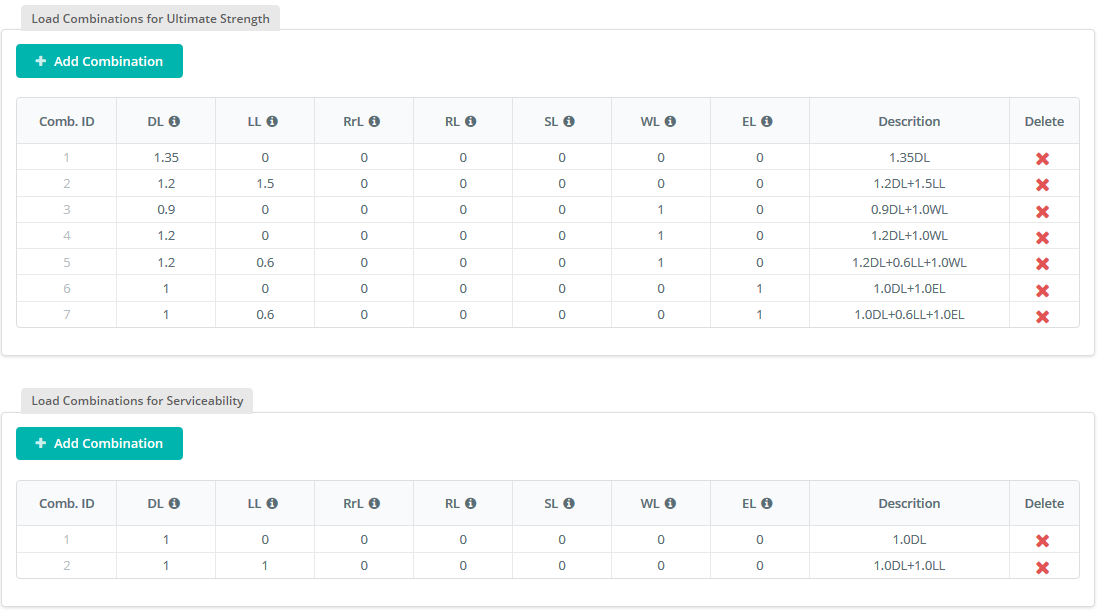
Une fois le tableau complété ou correctement rempli par l'utilisateur, il faut sauvegarder le travail en cliquant sur le “sauver” bouton.
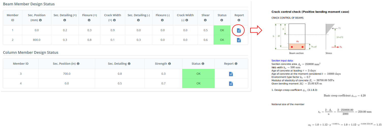
Résultats
Après avoir complété toutes les informations nécessaires à la conception de l'élément en béton, l'utilisateur peut enfin procéder à la conception en cliquant sur le “Vérifier la conception” bouton. Dans l'onglet Résultats, l'utilisateur peut visualiser les contrôles de conception et les ratios de capacité. Dans le module de conception, il existe des ratios de capacité pour chaque contrôle séparé comme le contrôle de flexion, contrôle de la force de cisaillement, contrôle des fissures et etc.. Pour un examen plus approfondi du calcul de conception, cliquer sur l'icône de rapport à la fin de la ligne générera un rapport de conception détaillé des vérifications effectuées par le module. Le rapport comprend toutes les formules de contrôle avec tous les paramètres décrits et les calculs manuels détaillés par rapport à la conception de la section en béton armé.