Exemple de conception de plaque de base utilisant AISC 360-22 et ACI 318-19
Déclaration de problème
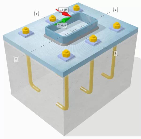
Déterminez si la connexion de colonne à base de colonne conçue est suffisante pour un VY = 2-Kip et VZ = 2 poulet charges de cisaillement.
Données données
Colonne:
Section colonne: HSS7X4X5 / 16
Zone de colonne: 7.59 in2
Matériau de colonne: A36
Plaque de base:
Dimensions de la plaque de base: 12 en x 14 in
Épaisseur de plaque de base: 3/4 in
Matériau de plaque de base: A36
Jointoyer:
Épaisseur de coulis: 0.25 in
Béton:
Dimensions du béton: 12 en x 14 in
Épaisseur de béton: 10 in
Matériau en béton: 3000 psi
Craquelé ou sans crates: Fissuré
Ancres:
Diamètre d'ancrage: 1/2 in
Durée d'admission efficace: 8 in
Épaisseur de laveuse de plaque: 0.25 in
Connexion de laveuse de plaque: Soudé à la plaque de base
Soudures:
Taille de soudure: 1/4 in
Classification du métal de remplissage: E70XX
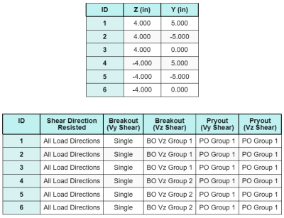
Ancrer les données (de Calculateur de skyciv):
Modèle dans l'outil gratuit SkyCiv
Modélisez la conception de la plaque de base ci-dessus à l'aide de notre outil en ligne gratuit dès aujourd'hui.! Aucune inscription requise.
Définitions
Chemin de chargement:
La conception suit les recommandations de Guide de conception AISC 1, 3édition rd, et ACI 318-19. Les charges de cisaillement appliquées à la colonne sont transférées sur la plaque de base à travers les soudures, puis au béton de support à travers le tiges d'ancrage. Les pirènes de frottement et de cisaillement ne sont pas prises en compte dans cet exemple, Comme ces mécanismes ne sont pas pris en charge dans le logiciel actuel.
Par défaut, L'application shear load is distributed to all anchors, soit par l'utilisation de rondelles de plaques soudées, soit par d'autres moyens techniques. La charge portée par chaque ancrage est déterminée à l'aide des trois (3) cas énoncés dans ACI 318-19 Clause 17.7.2 and Fig. R17.7.2.1b. Chaque ancrage transfère ensuite la charge au béton de support situé en dessous. La répartition des charges conformément à ces références est également utilisée lors de la vérification de la résistance au cisaillement de l'acier d'ancrage afin d'assurer la continuité des hypothèses de transfert de charge..
Comme alternative, Le logiciel permet une hypothèse simplifiée et plus conservatrice, où la charge de cisaillement entière n'est attribuée qu'au ancre les plus proches du bord chargé. Dans le cas présent, La vérification de la capacité de cisaillement est effectuée sur ces ancres de bord seul.
Groupes d'ancrage:
Ce logiciel Logiciel de conception de plaque de base SkyCiv Comprend une caractéristique intuitive qui identifie les ancres qui font partie d'un groupe d'ancrage pour évaluer rupture de cisaillement en béton et cisaillement en béton échecs.
Un groupe d'ancrage est défini comme deux ancres ou plus avec des zones de résistance projetées qui se chevauchent. Dans le cas présent, Les ancres agissent ensemble, Et leur résistance combinée est vérifiée par rapport à la charge appliquée sur le groupe.
A ancre unique est défini comme une ancre dont la zone de résistance projetée ne chevauche aucune autre. Dans le cas présent, L'ancre agit seul, et la force de cisaillement appliquée sur cette ancre est vérifiée directement contre sa résistance individuelle.
Cette distinction permet au logiciel de capturer le comportement du groupe et les performances individuelles de l'ancrage lors de l'évaluation des modes de défaillance liés au cisaillement.
Calculs étape par étape
Vérifier #1: Calculer la capacité de soudure
La première étape consiste à calculer le Longueur totale de soudure Disponible pour résister au cisaillement. Puisque la plaque de base est soudée le long du périmètre de la section colonne, La longueur totale de soudure est obtenue en additionnant les soudures de tous les côtés.
\( L_{souder} = 2 \la gauche( b_{col} – 2r_{col} – 2t_{col} \droite) + 2 \la gauche( ré_{col} – 2r_{col} – 2t_{col} \droite) \)
\( L_{souder} = 2 \fois (4\,\texte{in} – 2 \fois 0,291,texte{in} – 2 \fois 0,291,texte{in}) + 2 \fois (7\,\texte{in} – 2 \fois 0,291,texte{in} – 2 \fois 0,291,texte{in}) = 17.344,texte{in} \)
En utilisant cette longueur de soudure, les forces de cisaillement appliquées dans le y- et les directions z sont divisées pour déterminer la moyenne Force de cisaillement par unité de longueur dans chaque direction:
\( v_{ouais} = frac{V_y}{L_{souder}} = frac{2\,\texte{kip}}{17.344\,\texte{in}} = 0,11531,texte{kip / in} \)
\( v_{à} = frac{V_z}{L_{souder}} = frac{2\,\texte{kip}}{17.344\,\texte{in}} = 0,11531,texte{kip / in} \)
Ce logiciel cisaillement résultant Demande par unité de longueur est ensuite déterminé en utilisant la racine carrée de la somme des carrés (SRSS) méthode.
\( r_u = sqrt{(v_{ouais})^ 2 + (v_{à})^ 2} \)
\( r_u = sqrt{(0.11531\,\texte{kip / in})^ 2 + (0.11531\,\texte{kip / in})^ 2} = 0,16308,texte{kip / in} \)
Prochain, La capacité de soudure est calculée en utilisant AISC 360-22 Eq. J2-4, avec le coefficient de résistance directionnel pris comme kds = 1,0 pour une section HSS. La capacité de soudure pour un 1/4 en soudde est déterminé comme:
\( \Phi r_n = phi 0.6 F_{Exx} E_w k_{ds} = 0.75 \fois 0.6 \fois 70,texte{KSI} \fois 0,177,texte{in} \fois 1 = 5,5755,texte{kip / in} \)
Il est également nécessaire de vérifier les métaux de base, la colonne et la plaque de base, utilisant AISC 360-22 Eq. J4-4 Pour obtenir la résistance à la rupture de cisaillement. Cela donne:
\( \phi r_{Nbm, col} = phi 0.6 F_{u_col} t_{col} = 0.75 \fois 0.6 \fois 58,texte{KSI} \fois 0,291,texte{in} = 7,5951,texte{kip / in} \)
\( \phi r_{Nbm, pb} = phi 0.6 F_{u_bp} t_{pb} = 0.75 \fois 0.6 \fois 58,texte{KSI} \fois 0,75,texte{in} = 19,575,texte{kip / in} \)
\( \phi r_{Nbm} = mingauche( \phi r_{Nbm, pb},\, \phi r_{Nbm, col} \droite) = min(19.575\,\texte{kip / in},\, 7.5951\,\texte{kip / in}) = 7,5951,texte{kip / in} \)
Étant donné que la contrainte de soudure réelle est inférieure à la fois que les capacités de soudure en métal et en métal de base, 0.16308 kpi < 5.5755 kpi et 0.16308 kpi < 7.5951 kpi, La capacité de soudure de conception est suffisant.
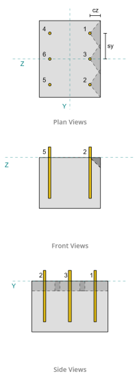
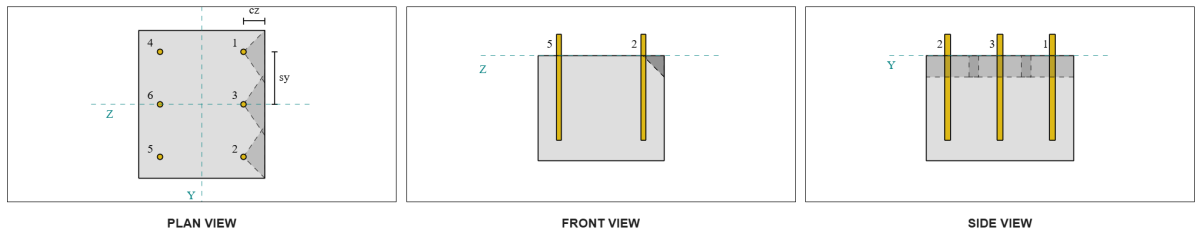
Vérifier #2: Calculer la capacité de rupture du béton en raison du cisaillement VY
Capacité de bord perpendiculaire:
De la disposition, Ancres 1 et 4 sont les plus proches du bord et ont le Distance CA1 la plus courte. En utilisant ces valeurs CA1 pour projeter les cônes de défaillance, le logiciel a identifié ces ancres comme ancres simples, Puisque leurs cônes projetés ne se chevauchent pas. Le soutien a également été déterminé à ne pas être un membre étroit, Ainsi, la distance CA1 est utilisée directement sans modification.
Rappelons que la force de cisaillement est supposée être distribuée entre toutes les ancres. Le calcul de la Charge de cisaillement VY appliqué à chaque ancre unique est:
\( V_{faperp} = frac{V_y}{n / A} = frac{2\,\texte{kip}}{6} = 0,33333,texte{kip} \)
Voyons Ancre 1. La zone projetée maximale d'une seule ancre est calculée en utilisant ACI 318-19 Eq. 17.7.2.1.3.
\( UNE_{Vco} = 4.5 (c_{A1, S1})À partir de l'élévation du sol générée à partir des élévations Google 4.5 \fois (2\,\texte{in})^2 = 18,texte{in}^ 2 \)
La zone projetée réelle est ensuite déterminée à partir de la largeur et de la hauteur du cône de défaillance projeté.
\( B_{U} = min(c_{la gauche,s1},\, 1.5c_{A1, S1}) + \min(c_{droite,s1},\, 1.5c_{A1, S1}) \)
\( B_{U} = min(10\,\texte{in},\, 1.5 \fois 2,texte{in}) + \min(2\,\texte{in},\, 1.5 \fois 2,texte{in}) = 5,texte{in} \)
\( H_{U} = min(1.5c_{A1, S1},\, t_{concurrence}) = min(1.5 \fois 2,texte{in},\, 10\,\texte{in}) = 3,texte{in} \)
\( UNE_{U} = B_{U} H_{U} = 5,texte{in} \fois 3,texte{in} = 15,texte{in}^ 2 \)
L'étape suivante consiste à utiliser Équations 17.7.2.2.1a et 17.7.2.2.1b Pour calculer la résistance à la rupture de base d'une seule ancre. La capacité de gouvernance est considérée comme la moindre valeur.
\( V_{b1} = 7 \la gauche( \frac{\min(le,\, 8d_a)}{d_a} \droite)^{0.2} \sqrt{\frac{d_a}{\texte{in}}} \lambda_a sqrt{\frac{f'_c}{\texte{psi}}} \la gauche( \frac{c_{A1, S1}}{\texte{in}} \droite)^{1.5} \,\texte{lbf} \)
\( V_{b1} = 7 \fois gauche( \frac{\min(8\,\texte{in},\, 8 \fois 0,5,texte{in})}{0.5\,\texte{in}} \droite)^{0.2} \fois sqrt{\frac{0.5\,\texte{in}}{1\,\texte{in}}} \fois 1 \fois sqrt{\frac{3\,\texte{KSI}}{0.001\,\texte{KSI}}} \fois gauche( \frac{2\,\texte{in}}{1\,\texte{in}} \droite)^{1.5} \fois 0,001,texte{kip} \)
\( V_{b1} = 1,1623,texte{kip} \)
\( V_{b2} = 9 \lambda_a sqrt{\frac{f'_c}{\texte{psi}}} \la gauche( \frac{c_{A1, S1}}{\texte{in}} \droite)^{1.5} \,\texte{lbf} \)
\( V_{b2} = 9 \fois 1 \fois sqrt{\frac{3\,\texte{KSI}}{0.001\,\texte{KSI}}} \fois gauche( \frac{2\,\texte{in}}{1\,\texte{in}} \droite)^{1.5} \fois 0,001,texte{kip} = 1,3943,texte{kip} \)
\( V_b = min(V_{b1},\, V_{b2}) = min(1.1623\,\texte{kip},\, 1.3943\,\texte{kip}) = 1,1623,texte{kip} \)
Prochain, l' Paramètres de capacité d'évasion sont déterminés. Ce logiciel Facteur d'effet de bord de rupture est calculé selon ACI 318-19 Clause 17.7.2.4, et la facteur d'épaisseur est calculé selon Clause 17.7.2.6.1.
\( \Psi_{ed,V} = mingauche(1.0,\, 0.7 + 0.3 \la gauche( \frac{c_{A2, S1}}{1.5c_{A1, S1}} \droite) \droite) = mingauche(1,\, 0.7 + 0.3 \fois gauche( \frac{2\,\texte{in}}{1.5 \fois 2,texte{in}} \droite) \droite) = 0.9 \)
\( \Psi_{h,V} = maxgauche( \sqrt{ \frac{1.5c_{A1, S1}}{t_{concurrence}} },\, 1.0 \droite) = maxgauche( \sqrt{ \frac{1.5 \fois 2,texte{in}}{10\,\texte{in}} },\, 1 \droite) = 1 \)
Ensuite, ACI 318-19 Clause 17.7.2.1(a) est utilisé pour déterminer la capacité de rupture en béton d'une seule ancre en cisaillement. La capacité calculée pour le cisaillement VY dans la direction perpendiculaire est 0.69 kips.
\( \phi V_{cbperp} = phi Left( \frac{UNE_{U}}{UNE_{Vco}} \droite) \Psi_{ed,V} \Psi_{c,V} \Psi_{h,V} V_b \)
\( \phi V_{cbperp} = 0.65 \fois gauche( \frac{15\,\texte{in}^ 2}{18\,\texte{in}^ 2} \droite) \fois 0.86 \fois 1 \fois 1 \fois 1,1623,texte{kip} = 0,56661,texte{kip} \)
La capacité calculée pour Vy Shear dans le perpendiculaire la direction est 0.56 kips.
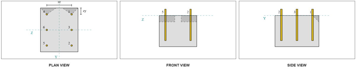
Capacité de bord parallèle:
Une défaillance le long du bord parallèle à la charge est également possible dans ce scénario, alors le Capacité de rupture en béton pour le bord parallèle Doit être déterminé. Les ancres ou le groupe d'ancrage considérés sont ceux qui sont alignés sur le bord parallèle. par conséquent, l' CA1 La distance du bord est mesurée de l'ancre au bord le long de la direction z. Basé sur la figure ci-dessous, Les projections du cône de défaillance se chevauchent; donc, Les ancres sont traitées comme un groupe.
Cas 1:
Cas 2:
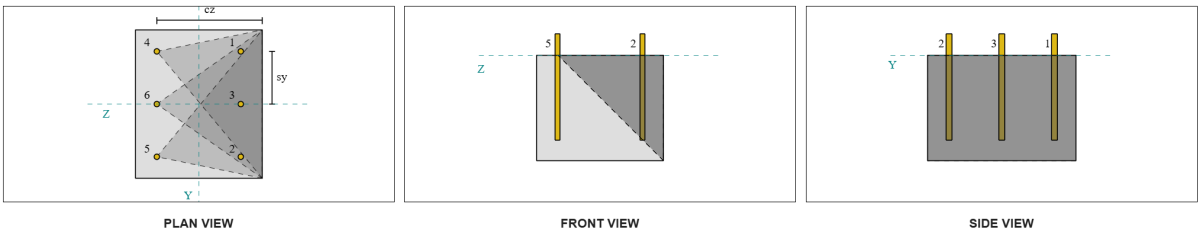
Nous nous référons à ACI 318-19 Fig. R17.7.2.1b Pour les différents cas utilisés lors de l'évaluation des groupes d'ancrage. Dans cette conception de plaque de base, rondelles à plaques soudées sont spécifiquement utilisés. Par conséquent, seul Cas 2 est vérifié.
La charge requise pour le groupe d'ancrage au cas où 2 est pris comme le Charge de cisaillement totale.
\( V_{faparallèle,cas2} = V_y = 2,texte{kip} \)
Pour calculer la capacité de l'affaire 2 échec, Les ancres considérées sont les ancres arrière. Donc, La distance du bord CA1 est mesurée du groupe d'ancrage arrière au bord de défaillance.
Avec cette distance de distance et de bord CA1, Il faut vérifier si le support est qualifié de membre étroit. Suivant ACI 318-19 Clause 17.7.2.1.2, Le logiciel de plaque de base Skyciv a identifié le support comme étroit. Par conséquent, l' Distance CA1 modifiée est utilisé, qui est calculé pour être 6.667 in.
Les mêmes étapes que dans le cas perpendiculaire sont suivis: Calcul du zones de défaillance projetées, l' Force de bascule de bascule unique, et la paramètres d'évasion. Les valeurs calculées pour chaque étape sont indiquées ci-dessous.
\( UNE_{Vco} = 4.5 (c_{«A1, G2})À partir de l'élévation du sol générée à partir des élévations Google 4.5 \fois (6.6667\,\texte{in})^2 = 200,texte{in}^ 2 \)
\( UNE_{U} = B_{U} H_{U} = 14,texte{in} \fois 10,texte{in} = 140,texte{in}^ 2 \)
\( V_{b1} = 7.0733,texte{kip} \)
\( V_{b2} = 8.4853,texte{kip} \)
\( V_b = min(V_{b1},\, V_{b2}) = min(7.0733\,\texte{kip},\, 8.4853\,\texte{kip}) = 7.0733,texte{kip} \)
\( \Psi_{ed,V} = 1.0 \)
\( \Psi_{h,V} = 1.0 \)
L'équation de la capacité de bord parallèle diffère de la capacité de bord perpendiculaire. ACI 318-19 Clause 17.7.2.1(c) est appliqué, où est l'équation en petits groupes multiplié par 2.
\( \phi V_{cbgparallèle} = 2 \phi gauche( \frac{UNE_{U}}{UNE_{Vco}} \droite) \Psi_{ed,V} \Psi_{c,V} \Psi_{h,V} V_b \)
\( \phi V_{cbgparallèle} = 2 \fois 0.65 \fois gauche( \frac{140\,\texte{in}^ 2}{200\texte{in}^ 2} \droite) \fois 1 \fois 1 \fois 1 \fois 7,0733,texte{kip} = 6,4367,texte{kip} \)
La capacité calculée pour Vy Shear dans le parallèle la direction est 6.43 kips.
Nous évaluons maintenant les échecs perpendiculaires et parallèles séparément.
- Pour la panne de bord perpendiculaire, puisque 0.33 kip < 0.56 kip, La capacité de cassure de cisaillement en béton est suffisant.
- Pour la panne de bord parallèle, puisque 2 kip < 6.43 kip, La capacité de cassure de cisaillement en béton est suffisant.
Vérifier #3: Calculer la capacité de rupture du béton dû au cisaillement VZ
La plaque de base est également soumise à Cisaillement vz, Ainsi, les bords de défaillance perpendiculaires et parallèles au cisaillement VZ doivent être vérifiés. En utilisant la même approche, Les capacités perpendiculaires et parallèles sont calculées comme 2.45 kips et 1.26 kips, respectivement.
Bord perpendiculaire:
Bord parallèle:
Ces capacités sont ensuite comparées aux forces requises.
- Pour la panne de bord perpendiculaire, puisque 2 kip < 2.45 kip, La capacité de rupture de cisaillement en béton est suffisant.
- Pour la panne de bord parallèle, puisque 0.33 kip < 1.26 kip, La capacité de rupture de cisaillement en béton est suffisant.
Vérifier #4: Calculer la capacité de pryout en béton
Ce logiciel Cône en béton pour défaillance de Pryout est le même cône utilisé dans le contrôle de rupture de traction. Pour calculer la capacité de cisaillement Pryout, La résistance à la traction de traction nominale des ancres uniques ou du groupe d'ancrage doit d'abord être déterminée. Les calculs détaillés pour le contrôle de rupture de traction sont déjà couverts dans le Exemples de conception de skyciv pour la charge de tension.
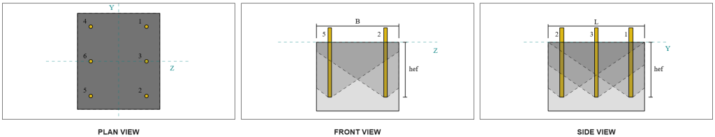
Il est important de noter que la détermination du groupe d'ancrage pour le cisaillement Pryout est différente de celle de la rupture de cisaillement. Par conséquent, Les ancres de la conception doivent toujours être vérifiées pour déterminer s'ils acte as a grouper ou comme ancres simples contre l'échec de Pryout de cisaillement. La classification du soutien en tant que section étroite doit également être vérifié et doit suivre les mêmes conditions utilisées pour rupture de tension.
À partir des calculs de Skyviv, l' force de rupture de traction nominale du groupe d'ancrage est 12.772 kips. Avec un facteur pryout de Kcp = 2, La capacité de conception Pryout est:
\( \phi V_{cpg} = hy k_{cp} N_{cbg} = 0.65 \fois 2 \fois 12.772 \,\texte{kip} = 16.604,texte{kip} \)
La force requise est la résultant des charges de cisaillement appliquées. Puisque toutes les ancres appartiennent à un seul groupe, Le cisaillement résultant total est affecté au groupe.
\( V_{faire} = sqrt{(V_y)^ 2 + (V_z)^ 2} = sqrt{(2\,\texte{kip})^ 2 + (2\,\texte{kip})^ 2} = 2,8284,texte{kip} \)
\( V_{faire} = gauche( \frac{V_{faire}}{n / A} \droite) n_{a,G1} = gauche( \frac{2.8284\,\texte{kip}}{6} \droite) \fois 6 = 2,8284,texte{kip} \)
Puisque la charge de cisaillement totale est inférieure à la capacité du groupe d'ancrage, 2.82 kips < 18.976 kips, La capacité de conception Pryout est suffisant.
Vérifier #5: Calculer la capacité de cisaillement de la tige d'ancrage
Rappelons que dans cet exemple de conception, Le cisaillement est distribué à toutes les ancres. La charge de cisaillement totale par ancre est donc la résultante de sa part de la charge VY et de sa part de la charge VZ.
\( v_{faire,Y} = frac{V_y}{n / A} = frac{2\,\texte{kip}}{6} = 0,33333,texte{kip} \)
\( v_{faire,z} = frac{V_z}{n / A} = frac{2\,\texte{kip}}{6} = 0,33333,texte{kip} \)
\( V_{faire} = sqrt{(v_{faire,Y})^ 2 + (v_{faire,z})^ 2} \)
\( V_{faire} = sqrt{(0.33333\,\texte{kip})^ 2 + (0.33333\,\texte{kip})^ 2} = 0,4714,texte{kip} \)
Cela donne le Stress de cisaillement sur la tige d'ancrage comme:
\( f_v = frac{V_{faire}}{UNE_{canne à pêche}} = frac{0.4714\,\texte{kip}}{0.19635\,\texte{in}^ 2} = 2.4008,texte{KSI} \)
Parce qu'une rondelle de plaque est présente, un charge de cisaillement excentrique est induit dans la tige d'ancrage. L'excentricité est prise comme la moitié de la distance mesurée du haut du support en béton au centre de la rondelle de la plaque, Comptabilité de l'épaisseur de la plaque de base. Se référer à Guide de conception AISC 1, 3Section de l'édition RD 4.3.3.
\( e = 0.5 \la gauche( \frac{t_{PW}}{2} + t_{pb} \droite) = 0.5 \fois gauche( \frac{0.25\,\texte{in}}{2} + 0.75\,\texte{in} \droite) = 0,4375,texte{in} \)
Le moment du cisaillement excentrique est ensuite exprimé comme un contrainte axiale dans la tige d'ancrage. En utilisant le module de section, La contrainte axiale due à ce moment est calculée comme:
\( Z_{canne à pêche} = frac{\pi}{32} (d_a)^3 = frac{\pi}{32} \fois (0.5\,\texte{in})^3 = 0,012272,texte{in}^ 3 \)
\( f_t = frac{V_{faire} e}{Z_{canne à pêche}} = frac{0.4714\,\texte{kip} \fois 0,4375,texte{in}}{0.012272\,\texte{in}^ 3} = 16.806,texte{KSI} \)
Capacité de cisaillement de tige d'ancrage ACI:
Suivant ACI 318-19 Clause 17.7.1, La force de conception est alors déterminée. A 0.8 facteur de réduction est appliqué en raison de la présence de coussinets de coulis. La capacité de conception est donc:
\( \phi V_{à,ici} = 0.8 \phi 0.6 UNE_{je connais,v} F_{uta} = 0.8 \fois 0.65 \fois 0.6 \fois 0,1419texte{in}^2 fois 90texte{KSI} = 3,9845texte{kip} \)
Comme alternative, l' Logiciel de plaque de base Skyciv permet au 0.8 simplification à désactiver, et utilisez l'épaisseur réelle du tampon de coulis dans les calculs. Dans le cas présent, L'excentricité totale comprend le tampon de coulis, et le cisaillement combiné et la résistance axiale sont déterminés conformément aux dispositions AISC.
Capacité de cisaillement de la tige d'ancrage AISC:
Première, l' cisaillement nominal et contrainte de traction sont déterminés pour une tige A325.
\( F_{nv} = 0.45 F_{u,anc} = 0.45 \fois 120\ \texte{KSI} = 54\ \texte{KSI} \)
\( F_{NT} = 0.75 F_{u,anc} = 0.75 \fois 120\ \texte{KSI} = 90\ \texte{KSI} \)
La méthode AISC utilise AISC 360-22 Eq. J3-3A, qui peut être exprimé pour inclure les effets de la contrainte axiale. Ceci est effectué comme suit.
\( F’_{nv} = min gauche( 1.3 F_{nv} – \la gauche( \frac{F_{nv}}{\Phi f_{NT}} \droite) f_t,\; F_{nv} \droite) \)
\( F’_{nv} = min gauche( 1.3 \fois 54\ \texte{KSI} – \la gauche( \frac{54\ \texte{KSI}}{0.75 \fois 90\ \texte{KSI}} \droite) \fois 16.806\ \texte{KSI},\; 54\ \texte{KSI} \droite) = 54\ \texte{KSI} \)
La capacité de cisaillement de conception de la méthode AISC est ensuite calculée comme:
\( \phi R_{n,\mathrm{AISC}} = phi F'_{nv} UNE_{canne à pêche} = 0.75 \fois 54\ \texte{KSI} \fois 0.19635\ \texte{in}À partir de l'élévation du sol générée à partir des élévations Google 7.9522\)
Pour s'assurer que les deux méthodes sont couvertes, la capacité de gouvernance est considérée comme le moindre des deux, lequel est 3.98 kip.
\( \phi V_n = min gauche( \phi V_{à,ici},\; \phi R_{n,\mathrm{AISC}} \droite) = min (3.9845\ \texte{kip},\; 7.9522\ \texte{kip}) = 3.9845\ \texte{kip} \)
Puisque la charge de cisaillement par tige d'ancrage est inférieure à la capacité de tige d'ancrage gouvernante en cisaillement, 0.47 kip < 3.98 kip, La capacité de cisaillement de la tige d'ancrage de conception est suffisant.
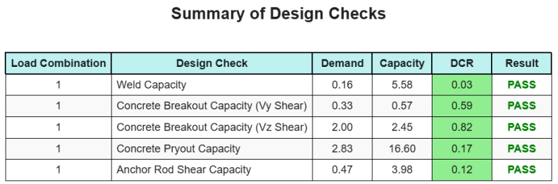
Résumé de la conception
Ce logiciel Logiciel de conception de plaques de base Skyciv peut générer automatiquement un rapport de calcul étape par étape pour cet exemple de conception. Il fournit également un résumé des contrôles effectués et de leurs ratios résultants, rendre les informations faciles à comprendre en un coup d'œil. Vous trouverez ci-dessous un échantillon de tableau de résumé, qui est inclus dans le rapport.
Rapport d'échantillon de skyciv
Découvrez le niveau de détail et de clarté que vous pouvez attendre d'un rapport de conception de plaque de base SkyCiv. Le rapport comprend toutes les vérifications de conception clés, équations, et les résultats présentés dans un format clair et facile à lire. Il est entièrement conforme aux normes de conception. Cliquez ci-dessous pour voir un exemple de rapport généré à l'aide du calculateur de plaque de base SkyCiv.
Logiciel d'achat de plaques de base
Achetez la version complète du module de conception de la plaque de base seul sans aucun autre module Skyviv. Cela vous donne un ensemble complet de résultats pour la conception de la plaque de base, y compris des rapports détaillés et plus de fonctionnalités.