Exemple de conception de plaque de base en utilisant EN 1993-1-8:2005, EN 1993-1-1:2005, EN 1992-1-1:2004, et EN 1992-4:2018.
Déclaration de problème
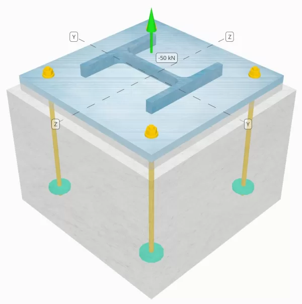
Déterminez si la connexion de colonne à base de colonne conçue est suffisante pour une charge de tension de 50 kN.
Données données
Colonne:
Section colonne: IL 240 B
Zone de colonne: 10600 mm2
Matériau de colonne: S235
Plaque de base:
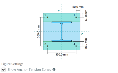
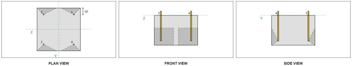
Dimensions de la plaque de base: 450 millimètre x 450 mm
Épaisseur de plaque de base: 20 mm
Matériau de plaque de base: S235
Jointoyer:
Épaisseur de coulis: 20 mm
Béton:
Dimensions du béton: 500 millimètre x 500 mm
Épaisseur de béton: 350 mm
Matériau en béton: C25/30
Craquelé ou sans crates: Fissuré
Ancres:
Diamètre d'ancrage: 12 mm
Durée d'admission efficace: 300.0 mm
Diamètre de la plaque intégrée: 60 mm
Épaisseur de plaque intégrée: 10 mm
Matériau d'ancrage: 8.8
Autres informations:
- Ancrages non fraisés.
- Ancre à fils coupés.
Soudures:
Type de soudure: FPBW
Classification du métal de remplissage: E35
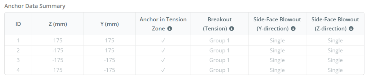
Ancrer les données (de Calculateur de skyciv):
Modèle dans l'outil gratuit SkyCiv
Modélisez la conception de la plaque de base ci-dessus à l'aide de notre outil en ligne gratuit dès aujourd'hui.! Aucune inscription requise.
Définitions
Zone de tension d'ancrage:
Dans le Logiciel de conception de plaque de base SkyCiv, seules les ancres situées dans le zone de tension ancre sont considérés comme efficaces pour résister à l'élévation. Cette zone comprend généralement des zones près des brides de colonne ou du Web. Les ancres à l'extérieur de cette zone ne contribuent pas à la résistance aux tensions et sont exclues des calculs de soulèvement.
L'hypothèse simplifie l'analyse de la plaque de base en approximant comment la force de soulèvement se propage à travers la plaque.
Groupes d'ancrage:
Ce logiciel Logiciel de conception de plaque de base SkyCiv Comprend une caractéristique intuitive qui identifie les ancres qui font partie d'un groupe d'ancrage pour évaluer évasion de béton et éruption de face latérale en béton échecs.
Un groupe d'ancrage se compose de plusieurs ancres avec des profondeurs et un espacement effectifs similaires, et sont suffisamment proches pour leur Les zones de résistance projetées se chevauchent. Lorsque les ancres sont regroupées, Leurs capacités sont combinées pour résister à la force de tension totale appliquée au groupe.
Les ancres qui ne répondent pas aux critères de regroupement sont traitées comme ancres simples. Dans le cas présent, Seule la force de tension sur l'ancre individuelle est vérifiée par rapport à sa propre zone de résistance efficace.
Calculs étape par étape
Vérifier #1: Calculer la capacité de soudure
A partir des informations données, la soudure utilisée dans cet exemple de conception est une Soudure bout à bout à pénétration totale (FPBW). Nous calculerons les capacités du métal de base de la colonne et de la plaque de base pour déterminer la résistance des soudures.. Pour faire ça, nous devons d'abord calculer le Longueur totale de soudure sur la colonne et obtenir la contrainte de soudure.
\(
F_{w,Ed} = frac{N_x}{2 b_f t_f + \la gauche( ré_{col} – 2 t_f – 2 r_{col} \droite) t_w}
\)
\(
F_{w,Ed} = frac{50 \, \texte{kN}}{2 \fois 240 \, \texte{mm} \fois 17 \, \texte{mm} + \la gauche( 240 \, \texte{mm} – 2 \fois 17 \, \texte{mm} – 2 \fois 21 \, \texte{mm} \droite) \fois 10 \, \texte{mm}} = 5.102 \, \texte{MPa}
\)
Prochain, Nous déterminons le résistance à la traction du matériau le plus faible entre la colonne et la plaque de base.
\(
f_y = min gauche( F_{Y,\texte{col}}, F_{Y,\texte{pb}} \droite) = min gauche( 225 \, \texte{MPa}, 225 \, \texte{MPa} \droite) = 225 \, \texte{MPa}
\)
On utilise alors EN 1993-1-8:2005 Clause 4.7.1 et EN 1993-1-1:2005 Eq. 6.6 pour calculer la résistance de soudure de conception FPBW.
\(
F_{w,Rd3} = frac{f_y}{\gamma_{M0}} = frac{225 \, \texte{MPa}}{1} = 225 \, \texte{MPa}
\)
Puisque 5.102 MPa < 225 MPa, La capacité de soudure est suffisant.
Vérifier #2: Calculer la capacité de rendement en flexion de la plaque de base due à la charge de tension
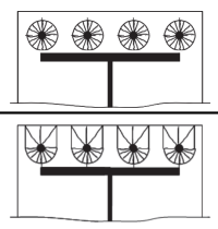
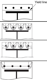
Pour calculer le capacité de flexion de la plaque de base contre la charge de tension, nous utiliserons modèles de lignes de rendement tels que des motifs circulaires et des motifs non circulaires. ensuite, nous déterminons la capacité de gouvernement, en supposant qu'il n'y ait aucune force indiscrète, en comparant la limite d'élasticité de la plaque avec la résistance à la traction des boulons d'ancrage.
Commencer, nous calculons le requis dimensions basé sur la disposition des boulons donnée. Se référer à EN 1992-1-8:2005 Le tableau 6.2 pour vous guider.
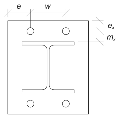
\(
m_x = frac{s_ – ré_{col}}{2} = frac{350 \, \texte{mm} – 240 \, \texte{mm}}{2} = 55 \, \texte{mm}
\)
\(
w = s_z gauche( n_{a,\texte{côté}} – 1 \droite) = 350 \, \texte{mm} \fois gauche( 2 – 1 \droite) = 350 \, \texte{mm}
\)
\(
e_x = frac{L_{pb} – s_}{2} = frac{450 \, \texte{mm} – 350 \, \texte{mm}}{2} = 50 \, \texte{mm}
\)
\(
e = frac{B_{pb} – w}{2} = frac{450 \, \texte{mm} – 350 \, \texte{mm}}{2} = 50 \, \texte{mm}
\)
\(
b_p = B_{pb} = 450 \, \texte{mm}
\)
Calculons également la distance du bord d'ancrage sur la plaque de base, qui est limité par le \( m_x \) dimension par
\(
n = min gauche( ex, 1.25 m_x droite) = min gauche( 50 \, \texte{mm}, 1.25 \fois 55 \, \texte{mm} \droite) = 50 \, \texte{mm}
\)
ensuite, nous calculons les longueurs efficaces des éléments suivants motifs circulaires (ils apparaîtraient en tant que membres rouges sur la structure afin que vous puissiez identifier les membres critiques et modifier votre conception Tableau SCI P398 5.3).
Motif circulaire 1:
\(
l_{eff,cp1} = n_{a,\texte{côté}} \pi m_x = 2 \fois pi fois 55 \, \texte{mm} = 345.58 \, \texte{mm}
\)
Motif circulaire 2:
\(
l_{eff,cp2} = gauche( \frac{n_{a,\texte{côté}}}{2} \droite) (\pi m_x + 2 ex) = gauche( \frac{2}{2} \droite) \fois (\Pi Times 55 \, \texte{mm} + 2 \fois 50 \, \texte{mm}) = 272.79 \, \texte{mm}
\)
Modèle circulaire directeur longueur effective:
\(
l_{eff,cp} = min (l_{eff,cp1}, l_{eff,cp2}) = min (345.58 \, \texte{mm}, 272.79 \, \texte{mm}) = 272.79 \, \texte{mm}
\)
Maintenant, nous calculons les longueurs efficaces des éléments suivants motifs non circulaires (ils apparaîtraient en tant que membres rouges sur la structure afin que vous puissiez identifier les membres critiques et modifier votre conception Tableau SCI P398 5.3)
Motif non circulaire 1:
\(
l_{eff,nc1} = frac{b_p}{2} = frac{450 \, \texte{mm}}{2} = 225 \, \texte{mm}
\)
Motif non circulaire 2:
\(
l_{eff,nc2} = gauche( \frac{n_{a,\texte{côté}}}{2} \droite) (4 m_x + 1.25 ex) = gauche( \frac{2}{2} \droite) \fois (4 \fois 55 \, \texte{mm} + 1.25 \fois 50 \, \texte{mm}) = 282.5 \, \texte{mm}
\)
Motif non circulaire 3:
\(
l_{eff,nc3} = 2 m_x + 0.625 ex + e = 2 \fois 55 \, \texte{mm} + 0.625 \fois 50 \, \texte{mm} + 50 \, \texte{mm} = 191.25 \, \texte{mm}
\)
Motif non circulaire 4:
\(
l_{eff,nc4} = 2 m_x + 0.625 ex + \frac{(n_{a,\texte{côté}} – 1) s_z}{2} = 2 \fois 55 \, \texte{mm} + 0.625 \fois 50 \, \texte{mm} + \frac{(2 – 1) \fois 350 \, \texte{mm}}{2} = 316.25 \, \texte{mm}
\)
Gouverner le modèle non circulaire longueur effective:
\(
l_{eff,Caroline du Nord} = min (l_{eff,nc1}, l_{eff,nc2}, l_{eff,nc3}, l_{eff,nc4}) = min (225 \, \texte{mm}, 282.5 \, \texte{mm}, 191.25 \, \texte{mm}, 316.25 \, \texte{mm}) = 191.25 \, \texte{mm}
\)
ensuite, nous déterminons la plus petite valeur entre les longueurs efficaces des motifs circulaires et non circulaires.
\(
l_{eff,1} = min (l_{eff,cp}, l_{eff,Caroline du Nord}) = min (272.79 \, \texte{mm}, 191.25 \, \texte{mm}) = 191.25 \, \texte{mm}
\)
Maintenant, nous utilisons cette longueur efficace calculée pour calculer sa résistance à la flexion. Selon EN 1993-1-8:2005 Le tableau 6.2, le moment de résistance de la plaque en cas de défaillance 1 est:
\(
M_{PL,1,Rd} = frac{0.25 l_{eff,1} (t_{pb})^ 2 f_{et _bp}}{\gamma_{M0}} = frac{0.25 \fois 191.25 \, \texte{mm} \fois (20 \, \texte{mm})^ 2 fois 225 \, \texte{MPa}}{1} = 4303.1 \, \texte{kN} \CDOT Texte{mm}
\)
Supposant pas de fouille, Nous utilisons en 1993-1-8:2005 Le tableau 6.2 pour déterminer le divers résistance de la plaque de base pour échec Modes 1 et 2.
\(
F_{T,1,Rd} = frac{2 M_{PL,1,Rd}}{m_x} = frac{2 \fois 4303.1 \, \texte{kN} \CDOT Texte{mm}}{55 \, \texte{mm}} = 156.48 \, \texte{kN}
\)
ensuite, nous calculons la résistance à la traction de la tige d'ancrage en utilisant EN 1992-4:2018 Clause 7.2.1.3. Cela sera plus détaillé dans les chèques d'ancrage suivants.
\(
F_{t,Rd} = frac{C k_2 f_{u _anc} Comme}{\gamma_{M2, ancre}} = frac{0.85 \fois 0.9 \fois 800 \, \texte{MPa} \fois 113.1 \, \texte{mm}^ 2}{1.25} = 55.372 \, \texte{kN}
\)
Nous utiliserons ensuite la résistance par tige d'ancrage pour calculer la résistance de calcul de la plaque de base en échec Mode 3, quelle est la défaillance totale du boulon.
\(
F_{T,3,Rd} = n_{a,côté} F_{t,Rd} = 2 \fois 55.372 \, \texte{kN} = 110.74 \, \texte{kN}
\)
Ensuite, nous déterminons la valeur de résistance déterminante parmi les modes de défaillance.
\(
F_{T,Rd} = min (F_{T,1,Rd}, F_{T,3,Rd}) = min (156.48 \, \texte{kN}, 110.74 \, \texte{kN}) = 110.74 \, \texte{kN}
\)
Calculer le charge de traction par bride, nous avons:
\(
F_{T,Ed} = frac{N_x}{2} = frac{50 \, \texte{kN}}{2} = 25 \, \texte{kN}
\)
Puisque 25 kN < 110.74 kN, La capacité de rendement en flexion de la plaque de base est suffisant.
Vérifier #3: Calculer la capacité de traction de la tige d'ancrage
Nous connaissons déjà la valeur de la capacité de traction de la tige d'ancrage., mais abordons-le plus en détail.
Première, calculons la zone de contrainte de traction de la tige d'ancrage.
\(
A_s = frac{\pi}{4} (ré_{anc})^ 2 = frac{\pi}{4} \fois (12 \, \texte{mm})À partir de l'élévation du sol générée à partir des élévations Google 113.1 \, \texte{mm}^ 2
\)
ensuite, appliquons les valeurs du \( c \) facteur et le \( afin que les ingénieurs puissent revoir exactement comment ces calculs sont effectués{2} \) facteur. Ces valeurs peuvent être modifiées dans les paramètres du logiciel SkyCiv Base Plate Design. Essayez la version gratuite ici.
- \( c = 0.85 \) pour chevilles avec filetage coupé
- \( afin que les ingénieurs puissent revoir exactement comment ces calculs sont effectués{2} = 0.9\) pour cheville non fraisée
Maintenant, utilisons EN 1992-4:2018 Clause 7.2.1.3 Pour calculer le résistance de calcul de la tige d'ancrage en tension.
\(
N_{Rd,s} = frac{C k_2 f_{u _anc} Comme}{\gamma_{M2, ancre}} = frac{0.85 \fois 0.9 \fois 800 \, \texte{MPa} \fois 113.1 \, \texte{mm}^ 2}{1.25} = 55.372 \, \texte{kN}
\)
Calculer le Charge de tension par ancre, nous avons:
\(
N_{Ed} = frac{N_x}{n_{a,t}} = frac{50 \, \texte{kN}}{4} = 12.5 \, \texte{kN}
\)
Puisque 12.5 kN < 55.372 kN, La capacité de traction de la tige d'ancrage est suffisant.
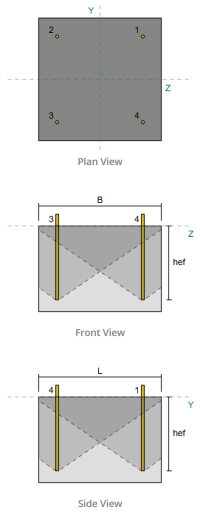
Vérifier #4: Calculer la capacité de rupture du béton en tension
Avant de calculer la capacité d'évasion, Nous devons d'abord déterminer si le membre est qualifié membre étroit. Selon EN 1992-4:2008 Clause 7.2.1.4(8), Le membre répond aux critères d'un membre étroit. Par conséquent, a modifié durée d'admission efficace doit être utilisé dans les calculs de capacité de coupure. Cet ajustement affecte également le espacement caractéristique et distance caractéristique au bord, qui doit être modifié en conséquence.
Basé sur les critères restreints des membres, l' valeurs modifiées pour le groupe d'ancrage sont les suivants:
- Longueur d'accès efficace modifiée, \( H’_{ef} = 100 mm \)
- espacement caractéristique modifié, \( s'_{cr} = 300 mm)
- distance au bord caractéristique modifiée, \( c'_{cr} = 150 mm)
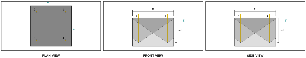
En utilisant EN 1992-4:2018 Eq. 7.3, on calcule le zone de cône de béton projetée de référence pour une seule ancre.
\(
A0_{c,N} = s'_{cr,G1} s'_{cr,G1} = 350 \, \texte{mm} \fois 350 \, \texte{mm} = 122500 \, \texte{mm}^ 2
\)
De manière similaire, on calcule le Zone de cône en béton projeté du groupe d'ancrage.
\(
UNE_{NC} = L_{NC} B_{NC} = 500 \, \texte{mm} \fois 500 \, \texte{mm} = 250000 \, \texte{mm}^ 2
\)
Où,
\(
L_{NC} = min gauche( c_{la gauche,G1}, c'_{cr,G1} \droite)
+ \la gauche( \min gauche( s_{somme,z,G1}, s'_{cr,G1} \la gauche( n_{z,G1} – 1 \droite) \droite) \droite)
+ \min gauche( c_{droite,G1}, c'_{cr,G1} \droite)
\)
\(
L_{NC} = min gauche( 75 \, \texte{mm}, 175 \, \texte{mm} \droite)
+ \la gauche( \min gauche( 350 \, \texte{mm}, 350 \, \texte{mm} \fois (2 – 1) \droite) \droite)
+ \min gauche( 75 \, \texte{mm}, 175 \, \texte{mm} \droite)
\)
\(
L_{NC} = 500 \, \texte{mm}
\)
\(
B_{NC} = min gauche( c_{Haut,G1}, c'_{cr,G1} \droite)
+ \la gauche( \min gauche( s_{somme,Y,G1}, s'_{cr,G1} \la gauche( n_{Y,G1} – 1 \droite) \droite) \droite)
+ \min gauche( c_{bas,G1}, c'_{cr,G1} \droite)
\)
\(
B_{NC} = min gauche( 75 \, \texte{mm}, 175 \, \texte{mm} \droite)
+ \la gauche( \min gauche( 350 \, \texte{mm}, 350 \, \texte{mm} \fois (2 – 1) \droite) \droite)
+ \min gauche( 75 \, \texte{mm}, 175 \, \texte{mm} \droite)
\)
\(
B_{NC} = 500 \, \texte{mm}
\)
Prochain, Nous évaluons le force caractéristique d'une seule ancre utilisant EN 1992-4:2018 Eq. 7.2
\(
N0_{afin que les ingénieurs puissent revoir exactement comment ces calculs sont effectués,c} = k_1 sqrt{\frac{F_{afin que les ingénieurs puissent revoir exactement comment ces calculs sont effectués}}{\texte{MPa}}} \la gauche( \frac{H’_{ef,G1}}{\texte{mm}} \droite)^{1.5} N
\)
\(
N0_{afin que les ingénieurs puissent revoir exactement comment ces calculs sont effectués,c} = 8.9 \fois sqrt{\frac{25 \, \texte{MPa}}{1 \, \texte{MPa}}} \fois gauche( \frac{116.67 \, \texte{mm}}{1 \, \texte{mm}} \droite)^{1.5} \fois 0.001 \, \texte{kN} = 56.076 \, \texte{kN}
\)
Où,
- \(afin que les ingénieurs puissent revoir exactement comment ces calculs sont effectués{1} = 8.9\) pour ancres coulées
Maintenant, nous évaluons les effets de la géométrie en calculant les paramètres pour la résistance à l'évasion.
La distance de bord la plus courte du groupe d'ancrage est déterminée comme:
\(
c_{min,N} = min gauche( c_{la gauche,G1}, c_{droite,G1}, c_{Haut,G1}, c_{bas,G1} \droite)
= min gauche( 87.5 \, \texte{mm}, 87.5 \, \texte{mm}, 150 \, \texte{mm}, 150 \, \texte{mm} \droite)
= 87.5 \, \texte{mm}
\)
Selon EN 1992-4:2018 Eq. 7.4, la valeur du paramètre prenant en compte la répartition des contraintes dans le béton est:
\(
\Psi_{s,N} = min gauche( 0.7 + 0.3 \la gauche( \frac{c_{min,N}}{c'_{cr,G1}} \droite), 1.0 \droite)
= min gauche( 0.7 + 0.3 \fois gauche( \frac{75 \, \texte{mm}}{175 \, \texte{mm}} \droite), 1 \droite)
= 0.82857
\)
Ce logiciel effet d'écaillage de la coque est comptabilisé en utilisant EN 1992-4:2018 Eq. 7.5, donner:
\(
\Psi_{= facteur de réduction pour filetage coupé,N} = min gauche( 0.5 + \frac{H’_{ef,G1}}{\texte{mm} \, / \, 200}, 1.0 \droite)
= min gauche( 0.5 + \frac{116.67 \, \texte{mm}}{1 \, \texte{mm} \, / \, 200}, 1 \droite)
= 1
\)
Aussi, les deux facteur d'excentricité et la facteur d'influence de la compression sont pris comme:
\(
\Psi_{ce,N} = 1
\)
\(
\Psi_{M,N} = 1
\)
Nous combinons ensuite tous ces facteurs et appliquons AS 5216:2021 Équation 6.2.3.1 pour évaluer le conception de la résistance à l'arrachement du cône en béton pour le groupe d'ancrage:
\(
N_{Rd,c} = frac{N0_{afin que les ingénieurs puissent revoir exactement comment ces calculs sont effectués,c} \la gauche( \frac{UNE_{NC}}{A0_{c,N}} \droite) \Psi_{s,N} \Psi_{= facteur de réduction pour filetage coupé,N} \Psi_{ce,N} \Psi_{M,N}}{\gamma_{Mc}}
\)
\(
N_{Rd,c} = frac{56.076 \, \texte{kN} \fois gauche( \frac{250000 \, \texte{mm}^ 2}{122500 \, \texte{mm}^ 2} \droite) \fois 0.82857 \fois 1 \fois 1 \fois 1}{1.5} = 63.215 \, \texte{kN}
\)
Ce logiciel Charge de tension appliquée totale sur le groupe d'ancrages est calculé en multipliant la charge de traction par ancrage par le nombre d'ancrages:
\(
N_{fa} = gauche( \frac{N_x}{n_{a,t}} \droite) n_{a,G1} = gauche( \frac{50 \, \texte{kN}}{4} \droite) \fois 4 = 50 \, \texte{kN}
\)
Puisque 50 kN < 63.215 kN La capacité de rupture en béton est suffisant.
Vérifier #5: Calculer la capacité d'arrachement de l'ancre
Ce logiciel capacité d'extraction d'une ancre est régie par la résistance à son extrémité encastrée. Pour commencer, on calcule le zone de roulement de la plaque encastrée, qui est la zone nette après avoir soustrait la zone occupée par la tige d'ancrage.
Première, nous calculons la dimension maximale de la tête d'ancrage efficace pour la résistance à l'arrachement, selon EN 1992-4:2018 Clause 7.2.1.5 Remarque.
\(
ré_{h,\texte{max}} = min gauche( b_{\texte{intégrer _plate}}, 6 \la gauche( t_{\texte{intégrer _plate}} \droite) + ré_{\texte{anc}} \droite)
= min gauche( 60 \, \texte{mm}, 6 \fois (10 \, \texte{mm}) + 12 \, \texte{mm} \droite)
= 60 \, \texte{mm}
\)
Prochain, nous calculons la surface d'appui nette de la plaque encastrée circulaire en utilisant:
\(
UNE_{brg} = frac{\pi}{4} \la gauche( \la gauche( ré_{h,\texte{max}} \droite)^ 2 – \la gauche( ré_{\texte{anc}} \droite)^ 2 à droite)
\)
\(
UNE_{brg} = frac{\pi}{4} \fois gauche( \la gauche( 60 \, \texte{mm} \droite)^ 2 – \la gauche( 12 \, \texte{mm} \droite)^ 2 à droite) = 2714.3 \, \texte{mm}^ 2
\)
On calcule ensuite le conception de la résistance à l'arrachement du béton d'ancrage coulé en tension à l'aide EN 1992-4:2018 Clause 7.2.1.5:
\(
N_{Rd,s} = frac{k_2 A_{brg} F_{afin que les ingénieurs puissent revoir exactement comment ces calculs sont effectués}}{\gamma_{MP}}
= frac{7.5 \fois 2714.3 \, \texte{mm}^ 2 fois 25 \, \texte{MPa}}{1.5}
= 339.29 \, \texte{kN}
\)
Rappelez-vous le calculé précédemment Charge de tension par ancre:
\(
N_{Ed} = frac{N_x}{n_{a,t}} = frac{50 \, \texte{kN}}{4} = 12.5 \, \texte{kN}
\)
Puisque 12.5 kN < 339.29 kN, La capacité de retrait de l'ancre est suffisant.
Vérifier #6: Calculer la capacité d'éruption de la face latérale dans la direction en y

Considérons l'ID d'ancrage #3. Nous commençons par calculer la distance au bord du bord de défaillance.
\(
c_{z,\texte{min}} = min gauche( c_{\texte{la gauche,s3}}, c_{\texte{droite,s3}} \droite)
= min gauche( 75 \, \texte{mm}, 425 \, \texte{mm} \droite)
= 75 \, \texte{mm}
\)
Prochain, nous déterminons la distance au bord du bord orthogonal.
\(
c_{Y,\texte{min}} = min gauche( c_{\texte{Haut,s3}}, c_{\texte{bas,s3}} \droite)
= min gauche( 425 \, \texte{mm}, 75 \, \texte{mm} \droite)
= 75 \, \texte{mm}
\)
En utilisant EN 1992-4:2018 Eq. 7.27, Calculons le surface projetée de référence d'une seule attache.
\(
A0_{c,Nb} = gauche( 4 c_{z,\texte{min}} \droite)^ 2
= gauche( 4 \fois 75 \, \texte{mm} \droite)^ 2
= 90000 \, \texte{mm}^ 2
\)
Puisque nous vérifions la capacité du groupe d'ancrage, prenons le superficie réelle projetée du groupe d'ancrage en utilisant EN 1992-4:2018 Eq. 7.27.
\(
UNE_{NC} = B_{c,Nb} H_{c,Nb} = 225 \, \texte{mm} \fois 200 \, \texte{mm} = 45000 \, \texte{mm}^ 2
\)
Où,
\(
B_{c,Nb} = 2 c_{z,\texte{min}} + \min gauche( 2 c_{z,\texte{min}}, c_{Y,\texte{min}} \droite)
= 2 \fois 75 \, \texte{mm} + \min gauche( 2 \fois 75 \, \texte{mm}, 75 \, \texte{mm} \droite)
= 225 \, \texte{mm}
\)
\(
H_{c,Nb} = 2 c_{z,\texte{min}} + \la gauche( \min gauche( t_{\texte{concurrence}} – h_{\texte{ef}}, 2 c_{z,\texte{min}} \droite) \droite)
= 2 \fois 75 \, \texte{mm} + \la gauche( \min gauche( 350 \, \texte{mm} – 300 \, \texte{mm}, 2 \fois 75 \, \texte{mm} \droite) \droite)
= 200 \, \texte{mm}
\)
En calculant le résistance caractéristique à l'éclatement du béton d'une ancre individuelle, nous utiliserons EN 1992-4:2018 Eq. 7.26.
\(
N0_{afin que les ingénieurs puissent revoir exactement comment ces calculs sont effectués,cb} = k_5 gauche( \frac{c_{z,\texte{min}}}{\texte{mm}} \droite)
\la gauche( \sqrt{\frac{UNE_{\texte{brg}}}{\texte{mm}^ 2}} \droite)
\la gauche( \sqrt{\frac{F_{afin que les ingénieurs puissent revoir exactement comment ces calculs sont effectués}}{\texte{MPa}}} \droite) N
\)
\(
N0_{afin que les ingénieurs puissent revoir exactement comment ces calculs sont effectués,cb} = 8.7 \fois gauche( \frac{75 \, \texte{mm}}{1 \, \texte{mm}} \droite)
\fois gauche( \sqrt{\frac{2714.3 \, \texte{mm}^ 2}{1 \, \texte{mm}^ 2}} \droite)
\fois gauche( \sqrt{\frac{25 \, \texte{MPa}}{1 \, \texte{MPa}}} \droite)
\fois 0.001 \, \texte{kN}
\)
\(
N0_{afin que les ingénieurs puissent revoir exactement comment ces calculs sont effectués,cb} = 169.97 \, \texte{kN}
\)
ensuite, nous obtiendrons le paramètres d'éruption latérale.
Le paramètre rendant compte de la perturbation de la répartition des contraintes dans le béton peut être calculé à partir de EN 1992-4:2018 Eq. 7.28.
\(
\Psi_{s,Nb} = min gauche( 0.7 + 0.3 \la gauche( \frac{c_{Y,\texte{min}}}{2 c_{z,\texte{min}}} \droite), 1.0 \droite)
= min gauche( 0.7 + 0.3 \fois gauche( \frac{75 \, \texte{mm}}{2 \fois 75 \, \texte{mm}} \droite), 1 \droite)
= 0.85
\)
Aussi, les facteurs d'effet de groupe et le facteur d'influence de l'excentricité sont les suivants:
\(
\Psi_{g,Nb} = 1
\)
\(
\Psi_{ce,N} = 1
\)
Ensuite, en référence à AS 5216:2021 Eq. 6.2.7 pour tiges d'ancrage à tête, l' conception de la résistance à l'éclatement du béton est:
\(
N_{afin que les ingénieurs puissent revoir exactement comment ces calculs sont effectués,cb} = frac{N0_{afin que les ingénieurs puissent revoir exactement comment ces calculs sont effectués,cb} \la gauche( \frac{UNE_{NC}}{A0_{c,Nb}} \droite) \la gauche( \Psi_{s,Nb} \droite) \la gauche( \Psi_{g,Nb} \droite) \la gauche( \Psi_{ce,N} \droite)}{\gamma_{Mc}}
\)
\(
N_{afin que les ingénieurs puissent revoir exactement comment ces calculs sont effectués,cb} = frac{169.97 \, \texte{kN} \fois gauche( \frac{45000 \, \texte{mm}^ 2}{90000 \, \texte{mm}^ 2} \droite) \fois gauche( 0.85 \droite) \fois gauche( 1 \droite) \fois gauche( 1 \droite)}{1.5} = 48.159 \, \texte{kN}
\)
Rappel Charge de tension par ancre:
\(
N_{Ed} = frac{N_x}{n_{a,t}} = frac{50 \, \texte{kN}}{4} = 12.5 \, \texte{kN}
\)
Puisque 12.5 kN < 48.159 kN, l'éruption de la face latérale du béton le long de la direction Y est suffisant.
Tout autre numéro d'identification d'ancre peut également être utilisé et donnera le même résultat, puisque le design est symétrique.
Vérifier #7: Calculer la capacité d'éruption de la face latérale dans la direction z
La même procédure est utilisée pour calculer la capacité d'éruption latérale dans la direction Z.. Considérons l'ID d'ancrage #2 cette fois. Encore une fois, nous commençons par calculer la distance au bord du bord de défaillance.
\(
c_{Y,\texte{min}} = min gauche( c_{\texte{Haut},s2}, c_{\texte{bas},s2} \droite)
= min gauche( 75 \, \texte{mm}, 425 \, \texte{mm} \droite)
= 75 \, \texte{mm}
\)
Prochain, nous déterminons la distance au bord du bord orthogonal.
\(
c_{z,\texte{min}} = min gauche( c_{\texte{la gauche},s2}, c_{\texte{droite},s2} \droite)
= min gauche( 75 \, \texte{mm}, 425 \, \texte{mm} \droite)
= 75 \, \texte{mm}
\)
En utilisant EN 1992-4:2018 Eq. 7.27, Calculons le surface projetée de référence d'une seule attache.
\(
A0_{c,Nb} = gauche( 4 c_{Y,\texte{min}} \droite)^ 2
= gauche( 4 \fois 75 \, \texte{mm} \droite)^ 2
= 90000 \, \texte{mm}^ 2
\)
Puisque nous vérifions la capacité du groupe d'ancrage, prenons le superficie réelle projetée du groupe d'ancrage en utilisant EN 1992-4:2018 Eq. 7.27.
\(
UNE_{NC} = B_{c,Nb} H_{c,Nb}
= 225 \, \texte{mm} \fois 200 \, \texte{mm}
= 45000 \, \texte{mm}^ 2
\)
Où,
\(
B_{c,Nb} = 2 c_{Y,\texte{min}} + \min gauche( 2 c_{Y,\texte{min}}, c_{z,\texte{min}} \droite)
= 2 \fois 75 \, \texte{mm} + \min gauche( 2 \fois 75 \, \texte{mm}, 75 \, \texte{mm} \droite)
= 225 \, \texte{mm}
\)
\(
H_{c,Nb} = 2 c_{Y,\texte{min}} + \la gauche( \min gauche( t_{\texte{concurrence}} – h_{\texte{ef}}, 2 c_{Y,\texte{min}} \droite) \droite)
= 2 \fois 75 \, \texte{mm} + \la gauche( \min gauche( 350 \, \texte{mm} – 300 \, \texte{mm}, 2 \fois 75 \, \texte{mm} \droite) \droite)
= 200 \, \texte{mm}
\)
En calculant le résistance caractéristique à l'éclatement du béton d'une ancre individuelle, nous utiliserons EN 1992-4:2018 Eq. 7.26.
\(
N0_{afin que les ingénieurs puissent revoir exactement comment ces calculs sont effectués,cb} = k_5 gauche( \frac{c_{Y,\texte{min}}}{\texte{mm}} \droite)
\sqrt{\la gauche( \frac{UNE_{brg}}{\texte{mm}^ 2} \droite)}
\sqrt{\la gauche( \frac{F_{afin que les ingénieurs puissent revoir exactement comment ces calculs sont effectués}}{\texte{MPa}} \droite)} \, \texte{N}
\)
\(
N0_{afin que les ingénieurs puissent revoir exactement comment ces calculs sont effectués,cb} = 8.7 \la gauche( \frac{75 \, \texte{mm}}{1 \, \texte{mm}} \droite)
\sqrt{\la gauche( \frac{2714.3 \, \texte{mm}^ 2}{1 \, \texte{mm}^ 2} \droite)}
\sqrt{\la gauche( \frac{25 \, \texte{MPa}}{1 \, \texte{MPa}} \droite)}
\cdot 0.001 \, \texte{kN}
\)
\(
N0_{afin que les ingénieurs puissent revoir exactement comment ces calculs sont effectués,cb} = 169.97 \, \texte{kN}
\)
ensuite, nous obtiendrons le paramètres d'éruption latérale.
Le paramètre rendant compte de la perturbation de la répartition des contraintes dans le béton peut être calculé à partir de EN 1992-4:2018 Eq. 7.28.
\(
\Psi_{s,Nb} = min gauche( 0.7 + 0.3 \la gauche( \frac{c_{z,\texte{min}}}{2 c_{Y,\texte{min}}} \droite), 1.0 \droite)
= min gauche( 0.7 + 0.3 \fois gauche( \frac{75 \, \texte{mm}}{2 \fois 75 \, \texte{mm}} \droite), 1 \droite)
= 0.85
\)
Aussi, les facteurs d'effet de groupe et le facteur d'influence de l'excentricité sont les suivants:
\(
\Psi_{g,Nb} = 1
\)
\(
\Psi_{ce,N} = 1
\)
Ensuite, en référence à AS 5216:2021 Eq. 6.2.7 pour tiges d'ancrage à tête, l' conception de la résistance à l'éclatement du béton est:
Rappel Charge de tension par ancre:
\(
N_{Ed} = frac{N_x}{n_{a,t}} = frac{50 \, \texte{kN}}{4} = 12.5 \, \texte{kN}
\)
Puisque 12.5 kN < 48.159 kN, l'éruption de la face latérale du béton le long de la direction Z est suffisant.
Tout autre numéro d'identification d'ancre peut également être utilisé et donnera le même résultat, puisque le design est symétrique.
Résumé de la conception
Ce logiciel Logiciel de conception de plaques de base Skyciv peut générer automatiquement un rapport de calcul étape par étape pour cet exemple de conception. Il fournit également un résumé des contrôles effectués et de leurs ratios résultants, rendre les informations faciles à comprendre en un coup d'œil. Vous trouverez ci-dessous un échantillon de tableau de résumé, qui est inclus dans le rapport.
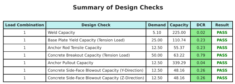
Rapport d'échantillon de skyciv
Découvrez le niveau de détail et de clarté que vous pouvez attendre d'un rapport de conception de plaque de base SkyCiv. Le rapport comprend toutes les vérifications de conception clés, équations, et les résultats présentés dans un format clair et facile à lire. Il est entièrement conforme aux normes de conception. Cliquez ci-dessous pour voir un exemple de rapport généré à l'aide du calculateur de plaque de base SkyCiv.
Logiciel d'achat de plaques de base
Achetez la version complète du module de conception de la plaque de base seul sans aucun autre module Skyviv. Cela vous donne un ensemble complet de résultats pour la conception de la plaque de base, y compris des rapports détaillés et plus de fonctionnalités.