Exemple de conception de plaque de base à l'aide de CSA S16:19 et CSA A23.3:19
Déclaration de problème
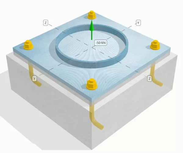
Déterminez si la connexion de colonne à base de colonne conçue est suffisante pour une charge de tension de 50 kN.
Données données
Colonne:
Section colonne: HS324X9.5
Zone de colonne: 9410 mm2
Matériau de colonne: 230g
Plaque de base:
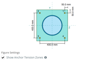
Dimensions de la plaque de base: 500 millimètre x 500 mm
Épaisseur de plaque de base: 20 mm
Matériau de plaque de base: 230g
Jointoyer:
Épaisseur de coulis: 20 mm
Béton:
Dimensions du béton: 550 millimètre x 550 mm
Épaisseur de béton: 200 mm
Matériau en béton: 20.68 MPa
Craquelé ou sans crates: Fissuré
Ancres:
Diamètre d'ancrage: 19.1 mm
Durée d'admission efficace: 130.0 mm
Longueur de crochet: 60mm
Distance de décalage d'ancrage de la face de la colonne: 120.84 mm
Soudures:
Type de soudure: Cjp
Classification du métal de remplissage: E43xx
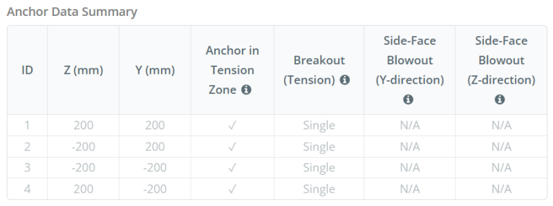
Ancrer les données (de Calculateur de skyciv):
Modèle dans l'outil gratuit SkyCiv
Modélisez la conception de la plaque de base ci-dessus à l'aide de notre outil en ligne gratuit dès aujourd'hui.! Aucune inscription requise.
Définitions
Chemin de chargement:
Lorsqu'une plaque de base est soumise à une augmentation (traction) les forces, Ces forces sont transférées sur les tiges d'ancrage, qui à son tour induit des moments de flexion dans l'assiette de base. L'action de flexion peut être visualisée comme flexion en porte-à-faux se produisant autour des brides ou du réseau de la section colonne, selon l'endroit où les ancres sont positionnées.
Dans le Logiciel de conception de plaque de base SkyCiv, seules les ancres situées dans le zone de tension ancre sont considérés comme efficaces pour résister à l'élévation. Cette zone comprend généralement des zones près des brides de colonne ou du Web. Dans le cas d'un colonne circulaire, La zone de tension d'ancrage comprend toute la zone à l'extérieur du périmètre de la colonne. Les ancres à l'extérieur de cette zone ne contribuent pas à la résistance aux tensions et sont exclues des calculs de soulèvement.
Pour déterminer la zone efficace de la plaque de base qui résiste à la flexion, a 45-dispersion de diplôme est supposé de la ligne médiane de chaque tige d'ancrage vers la face de la colonne. Cette dispersion définit le longueur de soudure efficace et aide à établir le largeur de flexion efficace de la plaque.
L'hypothèse simplifie l'analyse de la plaque de base en approximant comment la force de soulèvement se propage à travers la plaque.
Groupes d'ancrage:
Ce logiciel Logiciel de conception de plaque de base SkyCiv Comprend une caractéristique intuitive qui identifie les ancres qui font partie d'un groupe d'ancrage pour évaluer évasion de béton et éruption de face latérale en béton échecs.
Un groupe d'ancrage se compose de plusieurs ancres avec des profondeurs et un espacement effectifs similaires, et sont suffisamment proches pour leur Les zones de résistance projetées se chevauchent. Lorsque les ancres sont regroupées, Leurs capacités sont combinées pour résister à la force de tension totale appliquée au groupe.
Les ancres qui ne répondent pas aux critères de regroupement sont traitées comme ancres simples. Dans le cas présent, Seule la force de tension sur l'ancre individuelle est vérifiée par rapport à sa propre zone de résistance efficace.
Calculs étape par étape
Vérifier #1: Calculer la capacité de soudure
Pour commencer, Nous devons calculer la charge par ancre et déterminer la longueur de soudure effective pour chaque ancre. Ce logiciel longueur de soudure efficace est basé sur un 45° Ligne de dispersion tiré du centre de l'ancre à la face de la colonne. Si cette ligne de 45 ° n'inscrit pas la colonne, l' points tangents sont utilisés à la place. Aussi, Si les ancres sont étroitement espacées, La longueur de soudure effective est réduite pour éviter le chevauchement. Ensuite, La somme de toutes les longueurs de soudure efficaces ne doit pas dépasser la longueur de soudable réelle disponible le long de la circonférence de la colonne.
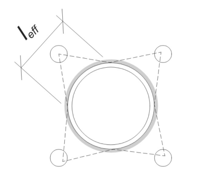
Appliquons cela à notre exemple. Basé sur la géométrie donnée, La ligne de 45 ° de l'ancre ne coupe pas la colonne. Donc, La longueur de l'arc entre les points tangents est utilisée à la place. Cette longueur d'arc doit également tenir compte des ancres adjacentes, avec toutes les parties qui se chevauchent soustraites pour éviter le double comptage. La longueur d'arc calculée est:
\(
l_{\texte{arc}} = 254.47 \, \texte{mm}
\)
Ce calcul de la longueur de l'arc est entièrement automatisé dans le logiciel de conception de la plaque de base Skyciv, Mais il peut également être effectué manuellement en utilisant des méthodes trigonométriques. Vous pouvez essayer l'outil gratuit à partir de ce lien.
Considérant la longueur soudable disponible le long de la circonférence de la colonne, la finale longueur de soudure efficace est:
\(
l_{\texte{eff}} = min gauche( l_{\texte{arc}}, \frac{\pi d_{\texte{col}}}{n_{a,t}} \droite) = min gauche( 254.47 \, \texte{mm}, \frac{\Pi Times 324 \, \texte{mm}}{4} \droite) = 254.47 \, \texte{mm}
\)
Prochain, Calculons le charge par ancre. Pour un ensemble donné de quatre (4) ancres, La charge par ancre est:
\(
T_{u,\texte{ancre}} = frac{N_x}{n_{a,t}} = frac{50 \, \texte{kN}}{4} = 12.5 \, \texte{kN}
\)
En utilisant la longueur de soudure efficace calculée, Nous pouvons maintenant calculer le Force requise par unité de longueur Agissant sur la soudure.
\(
v_f = frac{T_{u,\texte{ancre}}}{l_{\texte{eff}}} = frac{12.5 \, \texte{kN}}{254.47 \, \texte{mm}} = 0.049122 \, \texte{kN / mm}
\)
Maintenant, Nous nous référons à CSA S16:19 Clause 13.13.3.1 Pour calculer le Résistance factorisée de la pénétration articulaire complète (Cjp) souder. Cela nécessite la résistance au métal de base, exprimé en force par unité de longueur, Pour la colonne et les matériaux de la plaque de base.
\(
v_{r,\texte{BM}} = phi Left( \min gauche( F_{Y,\texte{col}} t_{\texte{col}}, F_{Y,\texte{pb}} t_{\texte{pb}} \droite) \droite)
\)
\(
v_{r,\texte{BM}} = 0.9 \fois gauche( \min gauche( 230 \, \texte{MPa} \fois 9.53 \, \texte{mm}, 230 \, \texte{MPa} \fois 20 \, \texte{mm} \droite) \droite) = 1.9727 \, \texte{kN / mm}
\)
Puisque 0.049122 kN / mm < 1.9727 kN / mm, La capacité de soudure est suffisant.
Vérifier #2: Calculer la capacité de rendement en flexion de la plaque de base due à la charge de tension
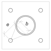
En utilisant la charge par ancre et le Distance de décalage du centre de l'ancre à la face de la colonne, Le moment appliqué à la plaque de base peut être calculé en utilisant un cantilever hypothèse. Pour une colonne circulaire, L'excentricité de charge est déterminée en considérant la sagitta de l'arc soudé, et peut être calculé comme suit:
\(
e_{\texte{tuyau}} = d_o + r_{\texte{col}} \la gauche( 1 – \car gauche( \frac{l_{\texte{eff}}}{2 r_{\texte{col}}} \droite) \droite)
\)
\(
e_{\texte{tuyau}} = 120.84 \, \texte{mm} + 162 \, \texte{mm} \fois gauche( 1 – \car gauche( \frac{254.47 \, \texte{mm}}{2 \fois 162 \, \texte{mm}} \droite) \droite) = 168.29 \, \texte{mm}
\)
Le moment induit est calculé comme:
\(
M_f = t_{u,\texte{ancre}} e_{\texte{tuyau}} = 12.5 \, \texte{kN} \fois 168.29 \, \texte{mm} = 2103.6 \, \texte{kN} \CDOT Texte{mm}
\)
Prochain, Nous déterminerons la largeur de flexion de la plaque de base. Pour ça, Nous utilisons le longueur de corde correspondant à l'arc de soudure efficace.
\(
\theta_{\texte{travailler}} = frac{l_{\texte{eff}}}{0.5 ré_{\texte{col}}} = frac{254.47 \, \texte{mm}}{0.5 \fois 324 \, \texte{mm}} = 1.5708
\)
\(
b = d_{\texte{col}} \la gauche( \péché gauche( \frac{\theta_{\texte{travailler}}}{2} \droite) \droite) = 324 \, \texte{mm} \fois gauche( \péché gauche( \frac{1.5708}{2} \droite) \droite) = 229.1 \, \texte{mm}
\)
Ensuite, Nous pouvons calculer le fasciné résistance à la flexion de la plaque de base en utilisant CSA S16:19 Clause 13.5.
\(
M_r = phi f_{Y,\texte{pb}} Z_{\texte{eff}} = 0.9 \fois 230 \, \texte{MPa} \fois 22910 \, \texte{mm}^ 3 = 4742.4 \, \texte{kN} \CDOT Texte{mm}
\)
Où,
\(
Z_{\texte{eff}} = frac{b (t_{\texte{pb}})^ 2}{4} = frac{229.1 \, \texte{mm} \fois (20 \, \texte{mm})^ 2}{4} = 22910 \, \texte{mm}^ 3
\)
Puisque 2103.6 kn-mm < 4742.4 kn-mm, La capacité de rendement en flexion de la plaque de base est suffisant.
Vérifier #3: Calculer la capacité de traction de la tige d'ancrage
Pour évaluer la capacité de traction de la tige d'ancrage, Nous nous référons à CSA A23.3:19 Clause D.6.1.2 et CSA S16:19 Clause 25.3.2.1.
Première, Nous déterminons le Force de traction spécifiée de l'acier d'ancrage. C'est la valeur la plus basse autorisée par CSA A23.3:19 Clause D.6.1.2.
\(
F_{\texte{uta}} = min gauche( F_{u,\texte{anc}}, 1.9 F_{Y,\texte{anc}}, 860 \droite) = min gauche( 400 \, \texte{MPa}, 1.9 \fois 248.2 \, \texte{MPa}, 860.00 \, \texte{MPa} \droite) = 400 \, \texte{MPa}
\)
Prochain, Nous déterminons le zone transversale efficace de la tige d'ancrage en tension en utilisant Manuel de conception du béton CAC, 3édition rd, Le tableau 12.3.
\(
UNE_{je connais,N} = 215 \, \texte{mm}^ 2
\)
Avec ces valeurs, Nous appliquons CSA A23.3:19 Eq. D.2 Pour calculer le résistance à la traction prise en compte de la tige d'ancrage.
\(
N_{\texte{sar}} = A_{je connais,N} \phi_s f_{\texte{uta}} R = 215 \, \texte{mm}^ 2 fois 0.85 \fois 400 \, \texte{MPa} \fois 0.8 = 58.465 \, \texte{kN}
\)
Aussi, Nous évaluons le résistance à la traction prise en compte selon CSA S16:19 Clause 25.3.2.1.
\(
T_r = phi_{ardente} 0.85 UNE_{ardente} F_{u,\texte{anc}} = 0.67 \fois 0.85 \fois 285.02 \, \texte{mm}^ 2 fois 400 \, \texte{MPa} = 64.912 \, \texte{kN}
\)
Après avoir comparé les deux, Nous identifions que la résistance factorisée calculée à l'aide de CSA A23.3:19 gouverne dans ce cas.
Rappelez-vous le calculé précédemment Charge de tension par ancre:
\(
N_{fa} = frac{N_x}{n_{a,t}} = frac{50 \, \texte{kN}}{4} = 12.5 \, \texte{kN}
\)
Puisque 12.5 kN < 58.465 kN, La capacité de traction de la tige d'ancrage est suffisant.
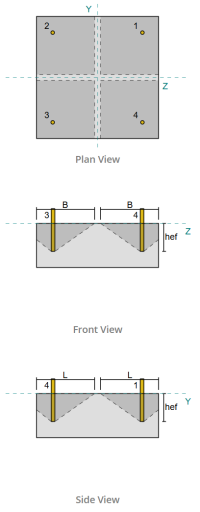
Vérifier #4: Calculer la capacité de rupture du béton en tension
Avant de calculer la capacité d'évasion, Nous devons d'abord déterminer si le membre est qualifié membre étroit. Selon CSA A23.3:19 Clause D.6.2.3, Le membre ne répond pas aux critères d'un membre étroit. Par conséquent, le donné durée d'admission efficace sera utilisé dans les calculs.
En utilisant CSA A23.3:19 Eq. D.5, on calcule le Zone de cône en béton maximum projeté pour une seule ancre, en fonction de la longueur d'introduction effective.
\(
UNE_{Rappelles toi} = 9 (h_{ef,s1})À partir de l'élévation du sol générée à partir des élévations Google 9 \fois (130 \, \texte{mm})À partir de l'élévation du sol générée à partir des élévations Google 152100 \, \texte{mm}^ 2
\)
De manière similaire, Nous utilisons la longueur effective de l'intégration pour calculer le Zone de cône en béton projeté de l'ancre unique.
\(
UNE_{NC} = L_{NC} B_{NC} = 270 \, \texte{mm} \fois 270 \, \texte{mm} = 72900 \, \texte{mm}^ 2
\)
Où,
\(
L_{NC} = gauche( \min gauche( c_{\texte{la gauche},s1}, 1.5 h_{ef,s1} \droite) \droite) + \la gauche( \min gauche( c_{\texte{droite},s1}, 1.5 h_{ef,s1} \droite) \droite)
\)
\(
L_{NC} = gauche( \min gauche( 475 \, \texte{mm}, 1.5 \fois 130 \, \texte{mm} \droite) \droite) + \la gauche( \min gauche( 75 \, \texte{mm}, 1.5 \fois 130 \, \texte{mm} \droite) \droite)
\)
\(
L_{NC} = 270 \, \texte{mm}
\)
\(
B_{NC} = gauche( \min gauche( c_{\texte{Haut},s1}, 1.5 h_{ef,s1} \droite) \droite) + \la gauche( \min gauche( c_{\texte{bas},s1}, 1.5 h_{ef,s1} \droite) \droite)
\)
\(
B_{NC} = gauche( \min gauche( 75 \, \texte{mm}, 1.5 \fois 130 \, \texte{mm} \droite) \droite) + \la gauche( \min gauche( 475 \, \texte{mm}, 1.5 \fois 130 \, \texte{mm} \droite) \droite)
\)
\(
B_{NC} = 270 \, \texte{mm}
\)
Prochain, Nous évaluons le fasciné Résistance à la rupture en béton de base d'une seule ancre utilisant CSA A23.3:19 Eq. D.6
\(
N_{br} = k_c phi lambda_a sqrt{\frac{f'_c}{\texte{MPa}}} \la gauche( \frac{h_{ef,s1}}{\texte{mm}} \droite)^{1.5} R n
\)
\(
N_{br} = 10 \fois 0.65 \fois 1 \fois sqrt{\frac{20.68 \, \texte{MPa}}{1 \, \texte{MPa}}} \fois gauche( \frac{130 \, \texte{mm}}{1 \, \texte{mm}} \droite)^{1.5} \fois 1 \fois 0.001 \, \texte{kN} = 43.813 \, \texte{kN}
\)
Où,
- \(afin que les ingénieurs puissent revoir exactement comment ces calculs sont effectués{c} = 10\) pour ancres coulées
- \(\lambda = 1.0 \) pour le béton de poids normal
Maintenant, Nous évaluons les effets de la géométrie en calculant facteur d'effet de bord.
La distance de bord la plus courte du groupe d'ancrage est déterminée comme:
\(
c_{a,\texte{min}} = min gauche( c_{\texte{la gauche},s1}, c_{\texte{droite},s1}, c_{\texte{Haut},s1}, c_{\texte{bas},s1} \droite) = min gauche( 475 \, \texte{mm}, 75 \, \texte{mm}, 75 \, \texte{mm}, 475 \, \texte{mm} \droite) = 75 \, \texte{mm}
\)
Selon CSA A23.3:19 Eq. D.10 et D.11, la rupture facteur d'effet de bord est:
\(
\Psi_{ed,N} = min gauche( 1.0, 0.7 + 0.3 \la gauche( \frac{c_{a,\texte{min}}}{1.5 h_{ef,s1}} \droite) \droite) = min gauche( 1, 0.7 + 0.3 \fois gauche( \frac{75 \, \texte{mm}}{1.5 \fois 130 \, \texte{mm}} \droite) \droite) = 0.81538
\)
Aussi, les deux facteur de fissuration et la facteur de division sont pris comme:
\(
\Psi_{c,N} = 1
\)
\(
\Psi_{cp,N} = 1
\)
ensuite, Nous combinons tous ces facteurs et utilisons ACI 318-19 Eq. 17.6.2.1b pour évaluer le fasciné résistance à la rupture en béton de l'ancre unique:
\(
N_{cbr} = gauche( \frac{UNE_{NC}}{UNE_{Rappelles toi}} \droite) \Psi_{ed,N} \Psi_{c,N} \Psi_{cp,N} N_{br} = gauche( \frac{72900 \, \texte{mm}^ 2}{152100 \, \texte{mm}^ 2} \droite) \fois 0.81538 \fois 1 \fois 1 \fois 43.813 \, \texte{kN} = 17.122 \, \texte{kN}
\)
Rappelez-vous le calculé précédemment Charge de tension par ancre:
\(
N_{fa} = frac{N_x}{n_{a,s}} = frac{50 \, \texte{kN}}{4} = 12.5 \, \texte{kN}
\)
Puisque 12.5 kN < 17.122 kN La capacité de rupture en béton est suffisant.
Ce calcul de rupture en béton est basé sur l'identifiant d'ancrage #1. La même capacité s'appliquera aux autres ancres en raison de la conception symétrique.
Vérifier #5: Calculer la capacité d'arrachement de l'ancre
La capacité de retrait d'une ancre est régie par la résistance à son extrémité intégrée. Pour les ancres accrochées, il dépend de sa longueur de crochet.
Nous calculons le Résistance à l'arrachement de l'ancre de base factorisé par CSA A23.3:19 Eq. D.17.
\(
N_{RP} = Psi_{c,p} 0.9 \phi (f'_c) e_h d_a r = 1 \fois 0.9 \fois 0.65 \fois (20.68 \, \texte{MPa}) \fois 60 \, \texte{mm} \fois 19.05 \, \texte{mm} \fois 1 = 13.828 \, \texte{kN}
\)
Rappelez-vous le calculé précédemment Charge de tension par ancre:
\(
N_{fa} = frac{N_x}{n_{a,t}} = frac{50 \, \texte{kN}}{4} = 12.5 \, \texte{kN}
\)
Puisque 12.5 kN < 13.828 kN, La capacité de retrait de l'ancre est suffisant.
Vérifier #6: Calculer la capacité d'éruption de la face latérale dans la direction en y
Ce calcul n'est pas applicable aux ancres accrochées.
Vérifier #7: Calculer la capacité d'éruption de la face latérale dans la direction z
Ce calcul n'est pas applicable aux ancres accrochées.
Résumé de la conception
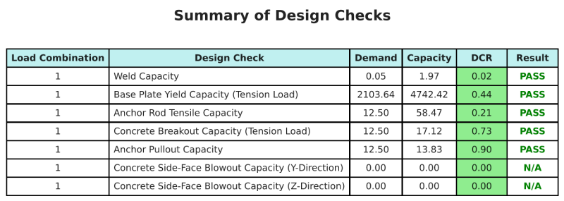
Ce logiciel Logiciel de conception de plaques de base Skyciv peut générer automatiquement un rapport de calcul étape par étape pour cet exemple de conception. Il fournit également un résumé des contrôles effectués et de leurs ratios résultants, rendre les informations faciles à comprendre en un coup d'œil. Vous trouverez ci-dessous un échantillon de tableau de résumé, qui est inclus dans le rapport.
Rapport d'échantillon de skyciv
Découvrez le niveau de détail et de clarté que vous pouvez attendre d'un rapport de conception de plaque de base SkyCiv. Le rapport comprend toutes les vérifications de conception clés, équations, et les résultats présentés dans un format clair et facile à lire. Il est entièrement conforme aux normes de conception. Cliquez ci-dessous pour voir un exemple de rapport généré à l'aide du calculateur de plaque de base SkyCiv.
Logiciel d'achat de plaques de base
Achetez la version complète du module de conception de la plaque de base ONITS sans aucun autre module Skyviv. Cela vous donne un ensemble complet de résultats pour la conception de la plaque de base, y compris des rapports détaillés et plus de fonctionnalités.