Exemple de conception de plaque de base en utilisant comme 4100:2020, AS 3600:2018, AS 5216:2021
Déclaration de problème
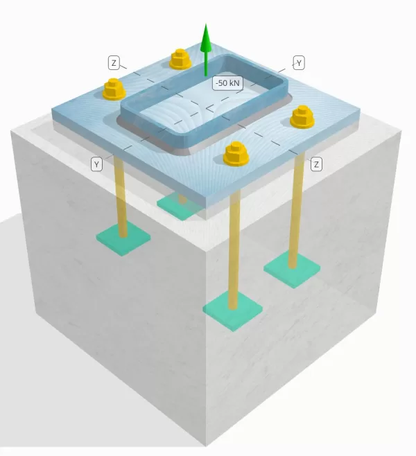
Déterminez si la connexion de colonne à base de colonne conçue est suffisante pour une charge de tension de 50 kN.
Données données
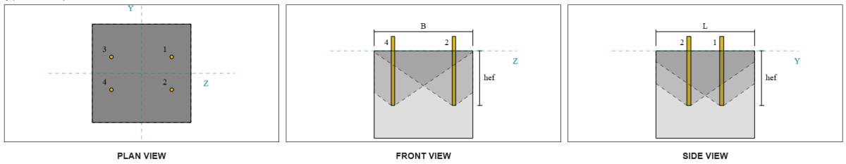
Colonne:
Section colonne: 250x150x8 RHS
Zone de colonne: 5920 mm2
Matériau de colonne: AS / NZS 1163 Grain. C350
Plaque de base:
Dimensions de la plaque de base: 350 millimètre x 350 mm
Épaisseur de plaque de base: 20 mm
Matériau de plaque de base: AS / NZS 1163 Grain. C250
Jointoyer:
Épaisseur de coulis: 20 mm
Béton:
Dimensions du béton: 450 millimètre x 450 mm
Épaisseur de béton: 400 mm
Matériau en béton: N28
Craquelé ou sans crates: Fissuré
Ancres:
Diamètre d'ancrage: 16 mm
Durée d'admission efficace: 250.0 mm
Largeur de plaque intégrée: 70 mm
Épaisseur de plaque intégrée: 10 mm
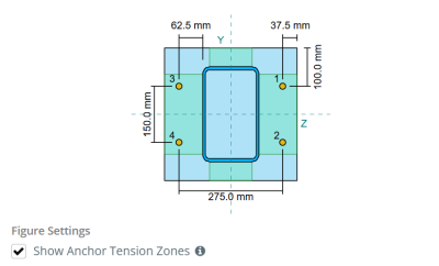
Distance de décalage d'ancrage de la face de la colonne: 62.5 mm
Soudures:
Type de soudure: Filet
Weld category: PS
Classification du métal de remplissage: E43xx
Ancrer les données (de Calculateur de skyciv):
Modèle dans l'outil gratuit SkyCiv
Modélisez la conception de la plaque de base ci-dessus à l'aide de notre outil en ligne gratuit dès aujourd'hui.! Aucune inscription requise.
Définitions
Chemin de chargement:
Lorsqu'une plaque de base est soumise à une augmentation (traction) les forces, Ces forces sont transférées sur les tiges d'ancrage, qui à son tour induit des moments de flexion dans l'assiette de base. L'action de flexion peut être visualisée comme flexion en porte-à-faux se produisant autour des brides ou du réseau de la section colonne, selon l'endroit où les ancres sont positionnées.
Dans le Logiciel de conception de plaque de base SkyCiv, seules les ancres situées dans le zone de tension ancre sont considérés comme efficaces pour résister à l'élévation. Cette zone comprend généralement des zones près des brides de colonne ou du Web. For rectangular columns, the anchor tension zone refers to the area adjacent to the column walls. Les ancres à l'extérieur de cette zone ne contribuent pas à la résistance aux tensions et sont exclues des calculs de soulèvement.
Pour déterminer la zone efficace de la plaque de base qui résiste à la flexion, a 45-dispersion de diplôme est supposé de la ligne médiane de chaque tige d'ancrage vers la face de la colonne. Cette dispersion définit le longueur de soudure efficace et aide à établir le largeur de flexion efficace de la plaque.
L'hypothèse simplifie l'analyse de la plaque de base en approximant comment la force de soulèvement se propage à travers la plaque.
Groupes d'ancrage:
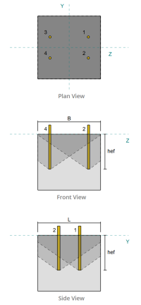
Ce logiciel Logiciel de conception de plaque de base SkyCiv Comprend une caractéristique intuitive qui identifie les ancres qui font partie d'un groupe d'ancrage pour évaluer évasion de béton et éruption de face latérale en béton échecs.
Un groupe d'ancrage se compose de plusieurs ancres avec des profondeurs et un espacement effectifs similaires, et sont suffisamment proches pour leur Les zones de résistance projetées se chevauchent. Lorsque les ancres sont regroupées, Leurs capacités sont combinées pour résister à la force de tension totale appliquée au groupe.
Les ancres qui ne répondent pas aux critères de regroupement sont traitées comme ancres simples. Dans le cas présent, Seule la force de tension sur l'ancre individuelle est vérifiée par rapport à sa propre zone de résistance efficace.
Prying Increase Factor:
Ce logiciel Logiciel de conception de plaque de base SkyCiv includes an option to apply a prying increase factor to account for additional tensile forces on the anchors due to prying action. This factor increases the load demand on the anchors during the anchor checks, providing a more conservative and realistic assessment where applicable. Par défaut, the prying increase factor is set to 1.0, meaning no additional prying load is applied unless specified by the user.
Calculs étape par étape:
Vérifier #1: Calculer la capacité de soudure
Pour commencer, Nous devons calculer la charge par ancre et la longueur de soudure efficace par ancre. The effective weld length is determined by the shortest length from the 45° dispersion, contraint par la longueur de soudure réelle et l'espacement de l'ancrage.
Pour ce calcul, Les ancres sont classées comme soit mettre fin aux ancres ou ancres intermédiaires. Les ancres d'extrémité sont situées aux extrémités d'une rangée ou d'une colonne d'ancres, tandis que les ancres intermédiaires sont positionnées entre elles. La méthode de calcul diffère pour chacune et dépend de la géométrie de la colonne. Dans cet exemple, Il y a deux ancres le long du Web, Et les deux sont classés comme des ancres de fin.
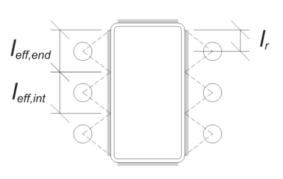
Pour les ancres de fin, the effective weld length is limited by the available distance from the anchor centerline to the column corner radius. La dispersion de 45 ° ne doit pas s'étendre au-delà de cette frontière.
\(
l_r = frac{ré_{col} – 2t_{col} – 2r_{col} – s_ (n_{a,\texte{côté}} – 1)}{2} = frac{250 \, \texte{mm} – 2 \fois 8 \, \texte{mm} – 2 \fois 12 \, \texte{mm} – 150 \, \texte{mm} \fois (2 – 1)}{2} = 30 \, \texte{mm}
\)
De côté intérieur, La longueur effective est limitée de la moitié de l'espacement de l'ancrage. La longueur totale de soudure effective pour l'ancre finale est la somme des longueurs extérieures et intérieures.
\(
l_{eff,fin} = min gauche( faire, 0.5 s_y \right) + \min gauche( faire, l_r \right)
\)
\(
l_{eff,fin} = min gauche( 62.5 \, \texte{mm}, 0.5 \fois 150 \, \texte{mm} \droite) + \min gauche( 62.5 \, \texte{mm}, 30 \, \texte{mm} \droite) = 92.5 \, \texte{mm}
\)
Dans cet exemple, the final effective weld length for the web anchor is taken as the effective length of the end anchor.
\(
l_{eff} = l_{eff,fin} = 92.5 \, \texte{mm}
\)
Prochain, let’s calculate the load per anchor. Pour un ensemble donné de quatre (4) ancres, La charge par ancre est:
\(
T_{u,ancre} = frac{N_x}{n_{a,t}} = frac{50 \, \texte{kN}}{4} = 12.5 \, \texte{kN}
\)
En utilisant la longueur de soudure efficace calculée, Nous pouvons désormais calculer la force requise par unité de longueur agissant sur la soudure.
\(
v ^ * _ w = frac{T_{u,ancre}}{l_{eff}} = frac{12.5 \, \texte{kN}}{92.5 \, \texte{mm}} = 0.13514 \, \texte{kN / mm}
\)
Maintenant, nous utiliserons AS 4100:2020 Clause 9.6.3.10 Pour calculer la force de conception de la soudure du filet.
\(
\Phi v_w = phi 0.6 F_{votre} E_w k_r = 0.8 \fois 0.6 \fois 430 \, \texte{MPa} \fois 5.657 \, \texte{mm} \fois 1 = 1.1676 \, \texte{kN / mm}
\)
In addition to checking the weld, we also need to verify the résistance du métal de base against the applied tension force to ensure it does not govern the failure mode.
\(
\phi v_{wbm} = phi Left( \min gauche( F_{et _col} t_{col}, F_{et _bp} t_{pb} \droite) \droite)
\)
\(
\phi v_{wbm} = 0.9 \fois gauche( \min gauche( 350 \, \texte{MPa} \fois 8 \, \texte{mm}, 250 \, \texte{MPa} \fois 20 \, \texte{mm} \droite) \droite) = 2.52 \, \texte{kN / mm}
\)
Dans le cas présent, the weld resistance governs over the base metal resistance.
Puisque 0.13514 kN / mm < 1.1676 kN / mm, La capacité de soudure est suffisant.
Vérifier #2: Calculer la capacité de rendement en flexion de la plaque de base due à la charge de tension
En utilisant le charge par ancre and the offset distance from the center of the anchor to the face of the column (servir d'excentricité de charge), Le moment appliqué à la plaque de base peut être calculé en utilisant un cantilever hypothèse.
\(
M^* = T_{u,ancre} e = 12.5 \, \texte{kN} \fois 62.5 \, \texte{mm} = 781.25 \, \texte{kN} \CDOT Texte{mm}
\)
Prochain, using the calculated longueur de soudure efficace from the previous check as the bending width, Nous pouvons calculer le SkyCiv Foundation est un module de conception pour la conception de semelles écartées à partir des charges de superstructure de la plaque de base en utilisant AISC 360-22, Équation 2-1:
\(
\phi M_s = \phi Z_{eff} F_{et _bp} = 0.9 \fois 9250 \, \texte{mm}^3 \times 250 \, \texte{MPa} = 2081.2 \, \texte{kN} \CDOT Texte{mm}
\)
Où,
\(
Z_{eff} = frac{l_{eff} (t_{pb})^ 2}{4} = frac{92.5 \, \texte{mm} \fois (20 \, \texte{mm})^ 2}{4} = 9250 \, \texte{mm}^ 3
\)
Puisque 781.25 kn-mm < 2081.2 kn-mm, La capacité de rendement en flexion de la plaque de base est suffisant.
Vérifier #3: Calculer la capacité de traction de la tige d'ancrage
To evaluate the tensile capacity of the anchor rod, Nous nous référons à AS 5216:2021 Clause 6.2.2 et AS 4100:2020 Clause 9.2.2.2.
Première, Nous déterminons le = facteur de réduction pour filetage coupé of the threaded portion of the rod, Suivant AS 4100:2020 Clause 7.2 et AS 1275–1985 Clause 1.7.
\(
A_n = \frac{\pi}{4} \la gauche( \frac{d_a}{\texte{mm}} – 0.9382 P \right)^ 2 \, \texte{mm}^ 2 = frac{\pi}{4} \fois gauche( \frac{16 \, \texte{mm}}{1 \, \texte{mm}} – 0.9382 \fois 2 \droite)^ 2 fois 1 \, \texte{mm}À partir de l'élévation du sol générée à partir des élévations Google 156.67 \, \texte{mm}^ 2
\)
En utilisant AS 4100:2020 Clause 9.2.2, on calcule le nominal tension capacity of the bolt based on the tensile stress area and the material strength.
\(
N_{tf} = A_n F_{u _anc} = 156.67 \, \texte{mm}^ 2 fois 800 \, \texte{MPa} = 125.33 \, \texte{kN}
\)
We then apply the appropriate resistance factor to obtain the design anchor capacity in tension.
\(
\phi N_{afin que les ingénieurs puissent revoir exactement comment ces calculs sont effectués,s} = \phi N_{tf} = 0.8 \fois 125.33 \, \texte{kN} = 100.27 \, \texte{kN}
\)
Rappelez-vous le calculé précédemment Charge de tension par ancre, and apply the prying increase factor if specified.
\(
N^* = p \left( \frac{N_x}{n_{a,t}} \droite) = 1 \fois gauche( \frac{50 \, \texte{kN}}{4} \droite) = 12.5 \, \texte{kN}
\)
Puisque 12.5 kN < 100.27 kN, l' anchor rod tensile capacity is sufficient.
Vérifier #4: Calculer la capacité de rupture du béton en tension
Avant de calculer la capacité d'évasion, Nous devons d'abord déterminer si le membre est qualifié membre étroit. Selon AS 5216:2021 Clause 6.2.3.8, Le membre répond aux critères d'un membre étroit. Par conséquent, a modifié durée d'admission efficace doit être utilisé dans les calculs de capacité de coupure. Cet ajustement affecte également le espacement caractéristique et distance caractéristique au bord, qui doit être modifié en conséquence.
Basé sur les critères restreints des membres, l' valeurs modifiées pour le groupe d'ancrage sont les suivants:
- Longueur d'accès efficace modifiée, \(H’_{ef} = 100 \, \texte{mm}\)
- espacement caractéristique modifié, \(s'_{cr} = 300 \, \texte{mm}\)
- distance au bord caractéristique modifiée, \(c'_{cr} = 150 \, \texte{mm}\)
En utilisant AS 5216: 2021 Clause 6.2.3.3, on calcule le zone de cône de béton projetée de référence pour une seule ancre.
\(
A0_{c,N} = gauche( s'_{cr,G1} \droite)^2 = \left( 300 \, \texte{mm} \droite)À partir de l'élévation du sol générée à partir des élévations Google 90000 \, \texte{mm}^ 2
\)
De manière similaire, on calcule le Zone de cône en béton projeté du groupe d'ancrage.
\(
UNE_{NC} = L_{NC} B_{NC} = 450 \, \texte{mm} \fois 450 \, \texte{mm} = 202500 \, \texte{mm}^ 2
\)
Où,
\(
L_{NC} = min gauche( c_{la gauche,G1}, c'_{cr,G1} + r_{intégrer _plate} \droite) + \min gauche( s_{somme,z,G1}, s'_{cr,G1} \cdot \left( n_{z,G1} – 1 \droite) \droite) + \min gauche( c_{droite,G1}, c'_{cr,G1} + r_{intégrer _plate} \droite)
\)
\(
L_{NC} = min gauche( 87.5 \, \texte{mm}, 150 \, \texte{mm} + 18 \, \texte{mm} \droite) + \min gauche( 275 \, \texte{mm}, 300 \, \texte{mm} \cdot (2 – 1) \droite) + \min gauche( 87.5 \, \texte{mm}, 150 \, \texte{mm} + 18 \, \texte{mm} \droite)
\)
\(
L_{NC} = 450 \, \texte{mm}
\)
\(
B_{NC} = min gauche( c_{Haut,G1}, c'_{cr,G1} + r_{intégrer _plate} \droite) + \min gauche( s_{somme,Y,G1}, s'_{cr,G1} \cdot \left( n_{Y,G1} – 1 \droite) \droite) + \min gauche( c_{bas,G1}, c'_{cr,G1} + r_{intégrer _plate} \droite)
\)
\(
B_{NC} =\min \left( 150 \, \texte{mm}, 150 \, \texte{mm} + 18 \, \texte{mm} \droite) + \min gauche( 150 \, \texte{mm}, 300 \, \texte{mm} \cdot (2 – 1) \droite) + \min gauche( 150 \, \texte{mm}, 150 \, \texte{mm} + 18 \, \texte{mm} \droite)
\)
\(
B_{NC} = 450 \, \texte{mm}
\)
Ce logiciel embedded plate effective radius is used to provide additional capacity for concrete breakout. Pour déterminer cela, add the thickness of the embedded plate to half of the anchor diameter.
Prochain, Nous évaluons le force caractéristique d'une seule ancre utilisant AS 5216:2021 Eq. 6.2.3.2
\(
N0_{afin que les ingénieurs puissent revoir exactement comment ces calculs sont effectués,c} = k_1 sqrt{\frac{f'_c}{\texte{MPa}}} \la gauche( \frac{H’_{ef,G1}}{\texte{mm}} \droite)^{1.5} \, \texte{N}
\)
\(
N0_{afin que les ingénieurs puissent revoir exactement comment ces calculs sont effectués,c} = 8.9 \fois sqrt{\frac{28 \, \texte{MPa}}{1 \, \texte{MPa}}} \fois gauche( \frac{100 \, \texte{mm}}{1 \, \texte{mm}} \droite)^{1.5} \fois 0.001 \, \texte{kN} = 47.094 \, \texte{kN}
\)
Où,
- \(afin que les ingénieurs puissent revoir exactement comment ces calculs sont effectués{1} = 8.9\) pour ancres coulées
Maintenant, nous évaluons les effets de la géométrie en calculant les paramètres pour la résistance à l'évasion.
La distance de bord la plus courte du groupe d'ancrage est déterminée comme:
\(
c_{min,N} = min gauche( c_{la gauche,G1}, c_{droite,G1}, c_{Haut,G1}, c_{bas,G1} \droite) = min gauche( 87.5 \, \texte{mm}, 87.5 \, \texte{mm}, 150 \, \texte{mm}, 150 \, \texte{mm} \droite) = 87.5 \, \texte{mm}
\)
Selon AS 5216:2021 Eq. 6.2.3.4, la valeur du paramètre prenant en compte la répartition des contraintes dans le béton est:
\(
\Psi_{s,N} = min gauche( 0.7 + 0.3 \la gauche( \frac{c_{min,N}}{c'_{cr,G1}} \droite), 1.0 \droite) = min gauche( 0.7 + 0.3 \fois gauche( \frac{87.5 \, \texte{mm}}{150 \, \texte{mm}} \droite), 1 \droite) = 0.875
\)
Ce logiciel effet d'écaillage de la coque est comptabilisé en utilisant AS 5216:2021 Équation 6.2.3.5, donner:
\(
\Psi_{= facteur de réduction pour filetage coupé,N} = min gauche( 0.5 + \frac{H’_{ef,G1}}{\texte{mm} \cdot 200}, 1.0 \droite) = min gauche( 0.5 + \frac{100 \, \texte{mm}}{1 \, \texte{mm} \cdot 200}, 1 \droite) = 1
\)
Aussi, les deux facteur d'excentricité et la facteur d'influence de la compression sont pris comme:
\(
\Psi_{ce,N} = 1
\)
\(
\Psi_{M,N} = 1
\)
Nous combinons ensuite tous ces facteurs et appliquons AS 5216:2021 Équation 6.2.3.1 pour évaluer le conception de la résistance à l'arrachement du cône en béton pour le groupe d'ancrage:
\(
\phi N_{afin que les ingénieurs puissent revoir exactement comment ces calculs sont effectués,c} = phi_{Mc} N0_{afin que les ingénieurs puissent revoir exactement comment ces calculs sont effectués,c} \la gauche( \frac{UNE_{NC}}{A0_{c,N}} \droite) \Psi_{s,N} \Psi_{= facteur de réduction pour filetage coupé,N} \Psi_{ce,N} \Psi_{M,N}
\)
\(
\phi N_{afin que les ingénieurs puissent revoir exactement comment ces calculs sont effectués,c} = 0.6667 \fois 47.094 \, \texte{kN} \fois gauche( \frac{202500 \, \texte{mm}^ 2}{90000 \, \texte{mm}^ 2} \droite) \fois 0.875 \fois 1 \fois 1 \fois 1 = 61.814 \, \texte{kN}
\)
Ce logiciel Charge de tension appliquée totale sur le groupe d'ancrages est calculé en multipliant la charge de traction par ancrage par le nombre d'ancrages, with the prying increase factor applied as needed:
\(
N^* = p \left( \frac{N_x}{n_{a,t}} \droite) n_{a,G1} = 1 \fois gauche( \frac{50 \, \texte{kN}}{4} \droite) \fois 4 = 50 \, \texte{kN}
\)
Puisque 50 kN < 61.814 kN La capacité de rupture en béton est suffisant.
Vérifier #5: Calculer la capacité d'arrachement de l'ancre
Ce logiciel capacité d'extraction d'une ancre est régie par la résistance à son extrémité encastrée. Première, nous calculons la dimension maximale de la tête d'ancrage efficace pour la résistance à l'arrachement, selon AS 5216:2021 Clause 6.3.4.
\(
ré_{h,\texte{max}} = min gauche( b_{intégrer _plate}, 6 \la gauche( t_{intégrer _plate} \droite) + d_a droite) = min gauche( 70 \, \texte{mm}, 6 \fois (10 \, \texte{mm}) + 16 \, \texte{mm} \droite) = 70 \, \texte{mm}
\)
Prochain, we calculate the net bearing area of the rectangular embedded plate using:
\(
A_h = \left( ré_{h,\texte{max}}^ 2 à droite) – UNE_{canne à pêche} = gauche( (70 \, \texte{mm})^ 2 à droite) – 201.06 \, \texte{mm}À partir de l'élévation du sol générée à partir des élévations Google 4698.9 \, \texte{mm}^ 2
\)
Où,
\(
UNE_{canne à pêche} = frac{\pi}{4} (d_a)^ 2 = frac{\pi}{4} \fois (16 \, \texte{mm})À partir de l'élévation du sol générée à partir des élévations Google 201.06 \, \texte{mm}^ 2
\)
On calcule ensuite le design basic anchor pullout strength utilisant AS 5216:2021 Clause 6.3.4:
\(
N_{afin que les ingénieurs puissent revoir exactement comment ces calculs sont effectués,p} = phi_{Mc} k_2 A_h \left( F’_C Right) = 0.6667 \fois 7.5 \fois 4698.9 \, \texte{mm}^ 2 fois (28 \, \texte{MPa}) = 657.88 \, \texte{kN}
\)
Rappelez-vous le calculé précédemment Charge de tension par ancre:
\(
N^* = p \left( \frac{N_x}{n_{a,t}} \droite) = 1 \fois gauche( \frac{50 \, \texte{kN}}{4} \droite) = 12.5 \, \texte{kN}
\)
Puisque 12.5 kN < 657.88 kN, La capacité de retrait de l'ancre est suffisant.
Vérifier #6: Calculer la capacité d'éruption de la face latérale dans la direction en y
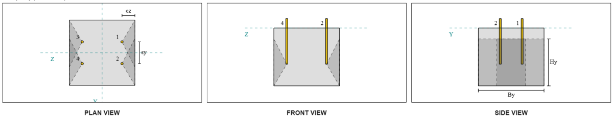
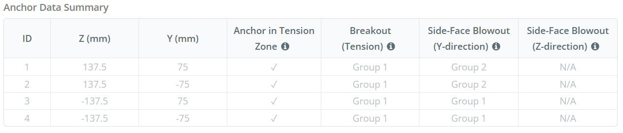
Let’s consider Side-Face Blowout Anchor Group 1 for the capacity calculation. Referring to the Anchor Data Summary, Anchor IDs 3 et 4 are part of SFy Group 1.
Nous commençons par calculer la distance au bord du bord de défaillance.
\(
c_{z,\texte{min}} = min gauche( c_{\texte{la gauche},G1}, c_{\texte{droite},G1} \droite) = min gauche( 87.5 \, \texte{mm}, 362.5 \, \texte{mm} \droite) = 87.5 \, \texte{mm}
\)
Prochain, nous déterminons la distance au bord du bord orthogonal.
\(
c_{Y,\texte{min}} = min gauche( c_{\texte{Haut},G1}, c_{\texte{bas},G1} \droite) = min gauche( 150 \, \texte{mm}, 150 \, \texte{mm} \droite) = 150 \, \texte{mm}
\)
En utilisant AS 5216:2021 Clause 6.2.7.3, Calculons le surface projetée de référence d'une seule attache.
\(
A0_{c,Nb} = gauche( 4 c_{z,\texte{min}} \droite)^2 = \left( 4 \fois 87.5 \, \texte{mm} \droite)À partir de l'élévation du sol générée à partir des élévations Google 122500 \, \texte{mm}^ 2
\)
Puisque nous vérifions la capacité du groupe d'ancrage, prenons le superficie réelle projetée du groupe d'ancrage en utilisant AS 5216:2021 Clause 6.2.7.2.
\(
UNE_{NC} = B_{c,Nb} H_{c,Nb} = 450 \, \texte{mm} \fois 325 \, \texte{mm} = 146250 \, \texte{mm}^ 2
\)
Où,
\(
B_{c,Nb} = min gauche( 2 c_{z,\texte{min}}, c_{\texte{Haut},G1} \droite) + s_{\texte{somme},Y,G1} + \min gauche( 2 c_{z,\texte{min}}, c_{\texte{bas},G1} \droite)
\)
\(
B_{c,Nb} = min gauche( 2 \fois 87.5 \, \texte{mm}, 150 \, \texte{mm} \droite) + 150 \, \texte{mm} + \min gauche( 2 \fois 87.5 \, \texte{mm}, 150 \, \texte{mm} \droite) = 450 \, \texte{mm}
\)
\(
H_{c,Nb} = 2 c_{z,\texte{min}} + \la gauche( \min gauche( t_{\texte{concurrence}} – h_{\texte{ef}}, 2 c_{z,\texte{min}} \droite) \droite)
\)
\(
H_{c,Nb} = 2 \fois 87.5 \, \texte{mm} + \la gauche( \min gauche( 400 \, \texte{mm} – 250 \, \texte{mm}, 2 \fois 87.5 \, \texte{mm} \droite) \droite) = 325 \, \texte{mm}
\)
En calculant le résistance caractéristique à l'éclatement du béton d'une ancre individuelle, nous utiliserons AS 5216:2021 Clause 6.2.7.2.
\(
N0_{afin que les ingénieurs puissent revoir exactement comment ces calculs sont effectués,cb} = k_5 gauche( \frac{c_{z,\texte{min}}}{\texte{mm}} \droite) \sqrt{\frac{A_h}{\texte{mm}^ 2}} \sqrt{\frac{f'_c}{\texte{MPa}}} \, N
\)
\(
N0_{afin que les ingénieurs puissent revoir exactement comment ces calculs sont effectués,cb} = 8.7 \fois gauche( \frac{87.5 \, \texte{mm}}{1 \, \texte{mm}} \droite) \fois sqrt{\frac{4698.9 \, \texte{mm}^ 2}{1 \, \texte{mm}^ 2}} \fois sqrt{\frac{28 \, \texte{MPa}}{1 \, \texte{MPa}}} \fois 0.001 \, \texte{kN}
\)
\(
N0_{afin que les ingénieurs puissent revoir exactement comment ces calculs sont effectués,cb} = 276.13 \, \texte{kN}
\)
Où,
- \(afin que les ingénieurs puissent revoir exactement comment ces calculs sont effectués{5} = 8.7\) pour béton fissuré
- \(afin que les ingénieurs puissent revoir exactement comment ces calculs sont effectués{5} = 12.2\) for uncracked concrete
ensuite, nous obtiendrons le paramètres d'éruption latérale.
Le paramètre rendant compte de la perturbation de la répartition des contraintes dans le béton peut être calculé à partir de AS 5216:2021 Clause 6.2.7.4.
\(
\Psi_{s,Nb} = min gauche( 0.7 + 0.3 \la gauche( \frac{c_{Y,\texte{min}}}{2 c_{z,\texte{min}}} \droite), 1.0 \droite)
\)
\(
\Psi_{s,Nb} = min gauche( 0.7 + 0.3 \fois gauche( \frac{150 \, \texte{mm}}{2 \fois 87.5 \, \texte{mm}} \droite), 1 \droite) = 0.95714
\)
The equation from AS 5216:2021 Clause 6.2.7.5 is then used to get the parameter accounting for the group effect.
\(
\Psi_{g,Nb} = max gauche( \sqrt{n_{Y,G1}} + \la gauche( 1 – \sqrt{n_{Y,G1}} \droite) \la gauche( \frac{\min gauche( s_{Y,G1}, 4 c_{z,\texte{min}} \droite)}{4 c_{z,\texte{min}}} \droite), 1.0 \droite)
\)
\(
\Psi_{g,Nb} = max gauche( \sqrt{2} + \la gauche( 1 – \sqrt{2} \droite) \fois gauche( \frac{\min gauche( 150 \, \texte{mm}, 4 \fois 87.5 \, \texte{mm} \droite)}{4 \fois 87.5 \, \texte{mm}} \droite), 1 \droite)
\)
\(
\Psi_{g,Nb} = 1.2367
\)
Ensuite, en référence à AS 5216:2021 Eq. 6.2.7 pour tiges d'ancrage à tête, l' conception de la résistance à l'éclatement du béton est:
\(
\phi N_{afin que les ingénieurs puissent revoir exactement comment ces calculs sont effectués,cb} = \phi_M N0_{afin que les ingénieurs puissent revoir exactement comment ces calculs sont effectués,cb} \la gauche( \frac{UNE_{NC}}{A0_{c,Nb}} \droite) \Psi_{s,Nb} \Psi_{g,Nb} \Psi_{ce,N}
\)
\(
\phi N_{afin que les ingénieurs puissent revoir exactement comment ces calculs sont effectués,cb} = 0.6667 \fois 276.13 \, \texte{kN} \fois gauche( \frac{146250 \, \texte{mm}^ 2}{122500 \, \texte{mm}^ 2} \droite) \fois 0.95714 \fois 1.2367 \fois 1 = 260.16 \, \texte{kN}
\)
For this anchor group, only two (2) anchors belong to group. Par conséquent, l' design tension force for the anchor group is:
\(
N^* = p \left( \frac{N_x}{n_{a,t}} \droite) n_{Y,G1}
\)
\(
N^* = 1 \fois gauche( \frac{50 \, \texte{kN}}{4} \droite) \fois 2 = 25 \, \texte{kN}
\)
Puisque 25 kN < 260.16 kN, l'éruption de la face latérale du béton le long de la direction Y est suffisant.
Side-Face Blowout Anchor Group 2 can also be used and will yield the same result, puisque le design est symétrique.
Vérifier #7: Calculer la capacité d'éruption de la face latérale dans la direction z
This calculation is not applicable for failure along the Z-direction, as the edge distance to the sides exceeds half of the effective embedment length.
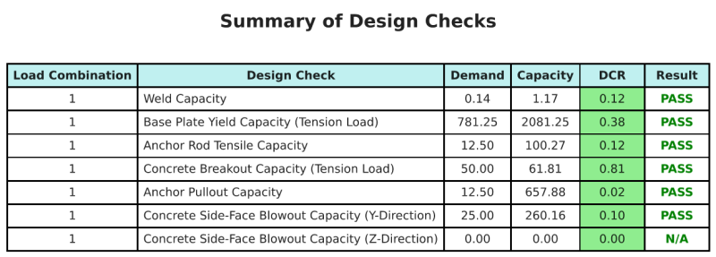
Résumé de la conception
Ce logiciel Logiciel de conception de plaques de base Skyciv peut générer automatiquement un rapport de calcul étape par étape pour cet exemple de conception. Il fournit également un résumé des contrôles effectués et de leurs ratios résultants, rendre les informations faciles à comprendre en un coup d'œil. Vous trouverez ci-dessous un échantillon de tableau de résumé, qui est inclus dans le rapport.
Rapport d'échantillon de skyciv
Découvrez le niveau de détail et de clarté que vous pouvez attendre d'un rapport de conception de plaque de base SkyCiv. Le rapport comprend toutes les vérifications de conception clés, équations, et les résultats présentés dans un format clair et facile à lire. Il est entièrement conforme aux normes de conception. Cliquez ci-dessous pour voir un exemple de rapport généré à l'aide du calculateur de plaque de base SkyCiv.
Logiciel d'achat de plaques de base
Achetez la version complète du module de conception de la plaque de base seul sans aucun autre module Skyviv. Cela vous donne un ensemble complet de résultats pour la conception de la plaque de base, y compris des rapports détaillés et plus de fonctionnalités.