Exemple de conception de plaque de base utilisant AISC 360-22 et ACI 318-19
Déclaration de problème
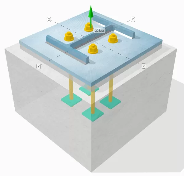
Déterminez si la connexion de colonne à base de colonne conçue est suffisante pour une charge de tension de 20 kip.
Données données
Colonne:
Section colonne: W12X53
Zone de colonne: 15.6 in2
Matériau de colonne: A992
Plaque de base:
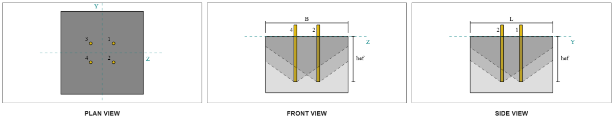
Dimensions de la plaque de base: 18 en x 18 in
Épaisseur de plaque de base: 3/4 in
Matériau de plaque de base: A36
Jointoyer:
Épaisseur de coulis: 1 in
Béton:
Dimensions du béton: 22 en x 22 in
Épaisseur de béton: 15 in
Matériau en béton: 4000 psi
Craquelé ou sans crates: Fissuré
Ancres:
Diamètre d'ancrage: 3/4 in
Durée d'admission efficace: 12 in
Largeur de plaque intégrée: 3 in
Épaisseur de plaque intégrée: 1/4 in
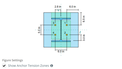
Ancrage de décalage distance de la face de la colonne Web: 2.8275 in
Soudures:
Taille de soudure: 1/4 in
Classification du métal de remplissage: E70XX
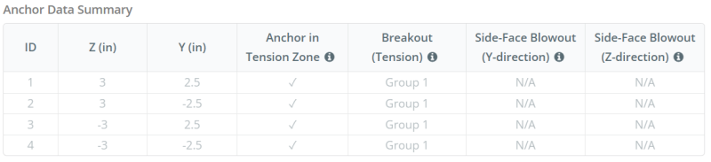
Ancrer les données (de Calculateur de skyciv):
Modèle dans l'outil gratuit SkyCiv
Modélisez la conception de la plaque de base ci-dessus à l'aide de notre outil en ligne gratuit dès aujourd'hui.! Aucune inscription requise.
Définitions
Chemin de chargement:
Lorsqu'une plaque de base est soumise à une augmentation (traction) les forces, Ces forces sont transférées sur les tiges d'ancrage, qui à son tour induit des moments de flexion dans l'assiette de base. L'action de flexion peut être visualisée comme flexion en porte-à-faux se produisant autour des brides ou du réseau de la section colonne, selon l'endroit où les ancres sont positionnées.
Dans le Logiciel de conception de plaque de base SkyCiv, seules les ancres situées dans le zone de tension ancre sont considérés comme efficaces pour résister à l'élévation. Cette zone comprend généralement des zones près des brides de colonne ou du Web. Les ancres à l'extérieur de cette zone ne contribuent pas à la résistance aux tensions et sont exclues des calculs de soulèvement.
Pour déterminer la zone efficace de la plaque de base qui résiste à la flexion, a 45-dispersion de diplôme est supposé de la ligne médiane de chaque tige d'ancrage vers la face de la colonne. Cette dispersion définit le longueur de soudure efficace et aide à établir le largeur de flexion efficace de la plaque.
L'hypothèse simplifie l'analyse de la plaque de base en approximant comment la force de soulèvement se propage à travers la plaque.
Groupes d'ancrage:
Ce logiciel Logiciel de conception de plaque de base SkyCiv Comprend une caractéristique intuitive qui identifie les ancres qui font partie d'un groupe d'ancrage pour évaluer évasion de béton et sid en bétonÉruption de l'e-face échecs.
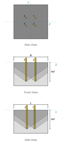
Un groupe d'ancrage se compose de plusieurs ancres avec des profondeurs et un espacement effectifs similaires, et sont suffisamment proches pour leur Les zones de résistance projetées se chevauchent. Lorsque les ancres sont regroupées, Leurs capacités sont combinées pour résister à la force de tension totale appliquée au groupe.
Les ancres qui ne répondent pas aux critères de regroupement sont traitées comme ancres simples. Dans le cas présent, Seule la force de tension sur l'ancre individuelle est vérifiée par rapport à sa propre zone de résistance efficace.
Calculs étape par étape
Vérifier #1: Calculer la capacité de soudure
Pour commencer, Nous devons calculer la charge par ancre et la longueur de soudure efficace par ancre. La longueur de soudure effective est déterminée par la plus courte longueur du 45° Dispersion, contraint par la longueur de soudure réelle et l'espacement de l'ancrage.
Pour ce calcul, Les ancres sont classées comme soit mettre fin aux ancres ou ancres intermédiaires. Les ancres d'extrémité sont situées aux extrémités d'une rangée ou d'une colonne d'ancres, tandis que les ancres intermédiaires sont positionnées entre elles. La méthode de calcul diffère pour chacune et dépend de la géométrie de la colonne. Dans cet exemple, Il y a deux ancres le long du Web, Et les deux sont classés comme des ancres de fin.
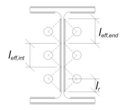
Pour les ancres de fin, La longueur de soudure effective est limitée par la distance disponible de la ligne centrale de l'ancre au filet de colonne. La dispersion de 45 ° ne doit pas s'étendre au-delà de cette frontière.
\(
l_r = frac{ré_{col} – 2t_f – 2r_{col} – s_(n_{a,côté} – 1)}{2} = frac{12.1 \, \texte{in} – 2 \fois 0.575 \, \texte{in} – 2 \fois 0.605 \, \texte{in} – 5 \, \texte{in} \fois (2 – 1)}{2} = 2.37 \, \texte{in}
\)
De côté intérieur, La longueur effective est limitée de la moitié de l'espacement de l'ancrage. La longueur totale de soudure effective pour l'ancre finale est la somme des longueurs extérieures et intérieures.
\(
l_{eff,fin} = min(faire, 0.5s_) + \min(faire, l_r)
\)
\(
l_{eff,fin} = min(2.8275 \, \texte{in}, 0.5 \fois 5 \, \texte{in}) + \min(2.8275 \, \texte{in}, 2.37 \, \texte{in}) = 4.87 \, \texte{in}
\)
Dans cet exemple, l' longueur de soudure efficace finale car l'ancre Web est considérée comme la longueur effective de l'ancre finale.
\(
l_{eff} = l_{eff,fin} = 4.87 \, \texte{in}
\)
Prochain, Calculons le charge par ancre. Pour un ensemble donné de quatre (4) ancres, La charge par ancre est:
\(
T_{u,ancre} = frac{N_x}{n_{a,t}} = frac{20 \, \texte{kip}}{4} = 5 \, \texte{kip}
\)
En utilisant la longueur de soudure efficace calculée, Nous pouvons maintenant déterminer le Force requise par unité de longueur sur la soudure.
\(
r_u = frac{T_{u,ancre}}{l_{eff}} = frac{5 \, \texte{kip}}{4.87 \, \texte{in}} = 1.0267 \, \texte{kip / in}
\)
Maintenant, nous utiliserons AISC 360-22, Chapitre J2.4 Pour calculer la force de conception de la soudure du filet.
Puisque la charge appliquée est une tension purement axiale, l'angle \(\thêta ) est pris à 90 °, et le coefficient de résistance directionnel KDS est calculé en fonction de AISC 360-22 Eq. J2-5.
\(
afin que les ingénieurs puissent revoir exactement comment ces calculs sont effectués{ds} = 1.0 + 0.5(\sin(\thêta ))^{1.5} = 1 + 0.5 \fois (\sin(1.5708))^{1.5} = 1.5
\)
Ensuite, nous appliquerons AISC 360-22 Eq. J2-4 pour déterminer le Force de conception de la soudure du filet par unité de longueur.
\(
\Phi r_n = phi 0.6 F_{Exx} E_{w,la toile} afin que les ingénieurs puissent revoir exactement comment ces calculs sont effectués{ds} = 0.75 \fois 0.6 \fois 70 \, \texte{KSI} \fois 0.177 \, \texte{in} \fois 1.5 = 8.3633 \, \texte{kip / in}
\)
Puisque 1.0267 kpi < 8.3633 kpi, La capacité de soudure est suffisant.
Vérifier #2: Calculer la capacité de rendement en flexion de la plaque de base due à la charge de tension
En utilisant til charge par ancre et le oFfset Distance du centre de l'ancre à la face de la colonne (servir d'excentricité de charge), Le moment appliqué à la plaque de base peut être calculé en utilisant un cantilever hypothèse.
\(
M_u = t_{u,\texte{ancre}} e = 5 \, \texte{kip} \fois 2.8275 \, \texte{in} = 14.137 \, \texte{kip} \CDOT Texte{in}
\)
Prochain, en utilisant le calculD Longueur de soudure efficace à l'extérieurm le chèque précédent comme largeur de flexion, Nous pouvons calculer le SkyCiv Foundation est un module de conception pour la conception de semelles écartées à partir des charges de superstructure de la plaque de base en utilisant AISC 360-22, Équation 2-1:
\(
\non -m_n = phi f_{Y,\texte{pb}} Z_{\texte{eff}} = 0.9 \fois 36 \, \texte{KSI} \fois 0.68484 \, \texte{in}^ 3 = 22.189 \, \texte{kip} \CDOT Texte{in}
\)
Où,
\(
Z_{\texte{eff}} = frac{l_{\texte{eff}} (t_{\texte{pb}})^ 2}{4} = frac{4.87 \, \texte{in} \fois (0.75 \, \texte{in})^ 2}{4} = 0.68484 \, \texte{in}^ 3
\)
Puisque 14.137 poulet dans < 22.189 poulet dans, La capacité de rendement en flexion de la plaque de base est suffisant.
Vérifier #3: Calculer la capacité de traction de la tige d'ancrage
Pour évaluer la capacité de traction de la tige d'ancrage, nous utiliserons ACI 318-19 Équation 17.6.1.2.
Première, Nous déterminons le Force de traction spécifiée de l'acier d'ancrage. C'est la valeur la plus basse autorisée par ACI 318-19 Clause 17.6.1.2, en référence aux propriétés des matériaux dans AISC 360-22 Tableau J3.2.
\(
F_{\texte{uta}} = min gauche( 0.75 F_{u,\texte{anc}}, 1.9 F_{Y,\texte{anc}}, 125 \droite) = min gauche( 0.75 \fois 120 \, \texte{KSI}, 1.9 \fois 92 \, \texte{KSI}, 125.00 \, \texte{KSI} \droite) = 90 \, \texte{KSI}
\)
Prochain, on calcule le zone transversale efficace de la tige d'ancrage. Ceci est basé sur ACI 318-19 Clause de commentaires R17.6.1.2, qui explique la géométrie du thread. Le nombre de fils par pouce est tiré de Tableau ASME B1.1-2019 1.
\(
UNE_{je connais,N} = frac{\pi}{4} \la gauche( d_a – \frac{0.9743}{n_t} \droite)^ 2 = frac{\pi}{4} \fois gauche( 0.75 \, \texte{in} – \frac{0.9743}{10 \, \texte{in}^{-1}} \droite)À partir de l'élévation du sol générée à partir des élévations Google 0.33446 \, \texte{in}^ 2
\)
Avec ces valeurs, Nous appliquons ACI 318-19 Équation 17.6.1.2 Pour calculer le Conception de la résistance à la traction de la tige d'ancrage.
\(
\phi N_{à} = phi A_{je connais,N} F_{\texte{uta}} = 0.75 \fois 0.33446 \, \texte{in}^ 2 fois 90 \, \texte{KSI} = 22.576 \, \texte{kip}
\)
Rappelez-vous le calculé précédemment Charge de tension par ancre:
\(
N_{faire} = frac{N_x}{n_{a,t}} = frac{20 \, \texte{kip}}{4} = 5 \, \texte{kip}
\)
Puisque 5 kip < 22.576 kip, La capacité de traction de la tige d'ancrage est suffisant.
Vérifier #4: Calculer la capacité de rupture du béton en tension
Avant de calculer la capacité d'évasion, Nous devons d'abord déterminer si le membre est qualifié membre étroit. Selon ACI 318-19 Clause 17.6.2.1.2, Le membre répond aux critères d'un membre étroit. Par conséquent, Une longueur d'admission efficace modifiée doit être utilisée dans les calculs.
Il est déterminé que le Longueur d'accès efficace modifiée, h’ef, du groupe d'ancrage est:
\(
H’_{\texte{ef}} = 5.667 \, \texte{in}
\)
En utilisant ACI 318-19 Clause 17.6.2, on calcule le Zone de cône en béton maximum projeté pour une seule ancre, basé sur la longueur d'admission efficace modifiée.
\(
UNE_{N_{co}} = 9 \la gauche( H’_{ef,G1} \droite)À partir de l'élévation du sol générée à partir des élévations Google 9 \fois gauche( 5.6667 \, \texte{in} \droite)À partir de l'élévation du sol générée à partir des élévations Google 289 \, \texte{in}^ 2
\)
De manière similaire, Nous utilisons la longueur d'admission effective modifiée pour calculer le Zone de cône en béton projeté du groupe d'ancrage.
\(
UNE_{Caroline du Nord} = min gauche( n_{a,G1} UNE_{N_{co}}, L_{Caroline du Nord} B_{Caroline du Nord} \droite) = min gauche( 4 \fois 289 \, \texte{in}^ 2, 22 \, \texte{in} \fois 22 \, \texte{in} \droite) = 484 \, \texte{in}^ 2
\)
Où,
\(
L_{Caroline du Nord} = min gauche( c_{\texte{la gauche},G1}, 1.5 H’_{\texte{ef},G1} \droite)
+ \la gauche( \min gauche( s_{\texte{somme},z,G1}, 3 H’_{\texte{ef},G1} \la gauche( n_{z,G1} – 1 \droite) \droite) \droite)
+ \min gauche( c_{\texte{droite},G1}, 1.5 H’_{\texte{ef},G1} \droite)
\)
\(
L_{Caroline du Nord} = min gauche( 8 \, \texte{in}, 1.5 \fois 5.6667 \, \texte{in} \droite)
+ \la gauche( \min gauche( 6 \, \texte{in}, 3 \fois 5.6667 \, \texte{in} \fois gauche( 2 – 1 \droite) \droite) \droite)
+ \min gauche( 8 \, \texte{in}, 1.5 \fois 5.6667 \, \texte{in} \droite)
\)
\(
L_{Caroline du Nord} = 22 \, \texte{in}
\)
\(
B_{Caroline du Nord} = min gauche( c_{\texte{Haut},G1}, 1.5 H’_{\texte{ef},G1} \droite)
+ \la gauche( \min gauche( s_{\texte{somme},Y,G1}, 3 H’_{\texte{ef},G1} \la gauche( n_{Y,G1} – 1 \droite) \droite) \droite)
+ \min gauche( c_{\texte{bas},G1}, 1.5 H’_{\texte{ef},G1} \droite)
\)
\(
B_{Caroline du Nord} = min gauche( 8.5 \, \texte{in}, 1.5 \fois 5.6667 \, \texte{in} \droite)
+ \la gauche( \min gauche( 5 \, \texte{in}, 3 \fois 5.6667 \, \texte{in} \fois gauche( 2 – 1 \droite) \droite) \droite)
+ \min gauche( 8.5 \, \texte{in}, 1.5 \fois 5.6667 \, \texte{in} \droite)
\)
\(
B_{Caroline du Nord} = 22 \, \texte{in}
\)
Prochain, Nous évaluons le Force de base en béton d'une seule ancre utilisant ACI 318-19 Clause 17.6.2.2.1
\(
N_b = k_c lambda_a sqrt{\frac{f'_c}{\texte{psi}}} \la gauche( \frac{H’_{\texte{ef},G1}}{\texte{in}} \droite)^{1.5} \, \texte{lbf}
\)
\(
N_b = 24 \fois 1 \fois sqrt{\frac{4 \, \texte{KSI}}{0.001 \, \texte{KSI}}} \fois gauche( \frac{5.6667 \, \texte{in}}{1 \, \texte{in}} \droite)^{1.5} \fois 0.001 \, \texte{kip} = 20.475 \, \texte{kip}
\)
Où,
- \(afin que les ingénieurs puissent revoir exactement comment ces calculs sont effectués{c} = 24\) pour ancres coulées
- \(\lambda = 1.0 \) pour le béton de poids normal
Maintenant, Nous évaluons les effets de la géométrie en calculant facteur d'effet de bord et la facteur d'excentricité.
La distance de bord la plus courte du groupe d'ancrage est déterminée comme:
\(
c_{a,\texte{min}} = min gauche( c_{\texte{la gauche},G1}, c_{\texte{droite},G1}, c_{\texte{Haut},G1}, c_{\texte{bas},G1} \droite)
= min gauche( 8 \, \texte{in}, 8 \, \texte{in}, 8.5 \, \texte{in}, 8.5 \, \texte{in} \droite) = 8 \, \texte{in}
\)
Selon ACI 318-19 Clause 17.6.2.4.1, la rupture facteur d'effet de bord est:
\(
\Psi_{ed,N} = min gauche( 1.0, 0.7 + 0.3 \la gauche( \frac{c_{a,\texte{min}}}{1.5 H’_{\texte{ef},G1}} \droite) \droite)
= min gauche( 1, 0.7 + 0.3 \fois gauche( \frac{8 \, \texte{in}}{1.5 \fois 5.6667 \, \texte{in}} \droite) \droite) = 0.98235
\)
Étant donné que la charge de tension est appliquée au centre de centroïde du groupe d'ancrage, L'excentricité est nul. C'est à dire, l' facteur d'excentricité, Aussi de la clause 17.6.2.4.1, est:
\(
\Psi_{ce,N} = min gauche( 1.0, \frac{1}{1 + \frac{2 et n}{3 H’_{\texte{ef},G1}}} \droite)
= min gauche( 1, \frac{1}{1 + \frac{2 \fois 0}{3 \fois 5.6667 \, \texte{in}}} \droite) = 1
\)
Aussi, les deux facteur de fissuration et la facteur de division sont pris comme:
\(
\Psi_{c,N} = 1
\)
\(
\Psi_{cp,N} = 1
\)
ensuite, Nous combinons tous ces facteurs et utilisons ACI 318-19 Eq. 17.6.2.1b pour évaluer le Force de rupture en béton du groupe d'ancrage:
\(
\phi N_{cbg} = phi Left( \frac{UNE_{Caroline du Nord}}{UNE_{N_{co}}} \droite) \Psi_{ce,N} \Psi_{ed,N} \Psi_{c,N} \Psi_{cp,N} N_b
\)
\(
\phi N_{cbg} = 0.7 \fois gauche( \frac{484 \, \texte{in}^ 2}{289 \, \texte{in}^ 2} \droite) \fois 1 \fois 0.98235 \fois 1 \fois 1 \fois 20.475 \, \texte{kip} = 23.58 \, \texte{kip}
\)
Ce logiciel Charge de tension appliquée totale Sur le groupe d'ancrage se trouve le produit de la charge individuelle de l'ancrage et du nombre d'ancres:
\(
N_{faire} = gauche( \frac{N_x}{n_{a,t}} \droite) n_{a,G1} = gauche( \frac{20 \, \texte{kip}}{4} \droite) \fois 4 = 20 \, \texte{kip}
\)
Puisque 20 kips < 23.58 kips, La capacité de rupture en béton est suffisant.
Vérifier #5: Calculer la capacité d'arrachement de l'ancre
La capacité de retrait d'une ancre est régie par la résistance à son extrémité intégrée. Pour commencer, Nous calculons la zone de roulement de la plaque intégrée, qui est la zone nette après avoir soustrait la zone occupée par la tige d'ancrage.
Pour une plaque intégrée rectangulaire, l' zone de roulement est calculé comme:
\(
UNE_{brg} = gauche( \la gauche( b_{intégrer _plate} \droite)^ 2 à droite) – UNE_{canne à pêche} = gauche( \la gauche( 3 \, \texte{in} \droite)^ 2 à droite) – 0.44179 \, \texte{in}À partir de l'élévation du sol générée à partir des élévations Google 8.5582 \, \texte{in}^ 2
\)
Où,
\(
UNE_{canne à pêche} = frac{\pi}{4} \la gauche( d_a droite)^ 2 = frac{\pi}{4} \fois gauche( 0.75 \, \texte{in} \droite)À partir de l'élévation du sol générée à partir des élévations Google 0.44179 \, \texte{in}^ 2
\)
Prochain, Nous déterminons le Force de retrait de l'ancre de base utilisant ACI 318-19 Équation 17.6.3.2.2a.
\(
N_b = 8 UNE_{brg} \la gauche( F’_C Right) = 8 \fois 8.5582 \, \texte{in}^ 2 Times Left( 4 \, \texte{KSI} \droite) = 273.86 \, \texte{kip}
\)
Nous appliquons ensuite le facteur de résistance approprié et Facteur de fissuration en retrait:
- Pour fissuré le béton, \(\Psi_{cp} = 1.0\)
- Pour sans casse le béton, \(\Psi_{cp} = 1.4\)
En utilisant ces, Nous calculons le Concevoir une résistance à l'arrachement de l'ancre en tension par ACI 318-19 Équation 17.6.3.1.
\(
\phi N_{pn} = Phi psi_{c,p} N_b = 0.7 \fois 1 \fois 273.86 \, \texte{kip} = 191.7 \, \texte{kip}
\)
Rappelez-vous le calculé précédemment Charge de tension par ancre:
\(
N_{faire} = frac{N_x}{n_{a,t}} = frac{20 \, \texte{kip}}{4} = 5 \, \texte{kip}
\)
Puisque 5 kips < 191.7 kips, La capacité de retrait de l'ancre est suffisant.
Vérifier #6: Calculer la capacité de flexion de la plaque intégrée
Ceci est un contrôle supplémentaire effectué en utilisant le Logiciel de conception de plaques de base Skyciv Pour vérifier que la plaque intégrée a une capacité de flexion suffisante et ne cédera pas sous les charges de retrait appliquées.
Première, Nous déterminons la longueur du libre (non pris en charge) fin de la plaque intégrée, mesuré du bord du soutien à la face de la tige.
\(
b’ = frac{b_{intégrer _plate} – d_a}{2} = frac{3 \, \texte{in} – 0.75 \, \texte{in}}{2} = 1.125 \, \texte{in}
\)
Prochain, on calcule le moments de flexion induit par la pression de roulement uniforme. Cette pression représente la force transférée de l'action de retrait de l'ancre sur la plaque intégrée.
\(
m_f = frac{\la gauche( \frac{T_a}{UNE_{brg}} \droite) \la gauche( b’ \droite)^ 2}{2} = frac{\la gauche( \frac{5 \, \texte{kip}}{8.5582 \, \texte{in}^ 2} \droite) \fois gauche( 1.125 \, \texte{in} \droite)^ 2}{2} = 0.36971 \, \texte{kip}
\)
Ensuite, en utilisant le moment calculé et donné des propriétés de matériau, Nous déterminerons le Épaisseur de plaque minimale requise résister rendement en flexion.
\(
t_{min} = sqrt{\frac{4 m_f}{\Phi f_{ouais}}} = sqrt{\frac{4 \fois 0.36971 \, \texte{kip}}{0.9 \fois 36 \, \texte{KSI}}} = 0.21364 \, \texte{in}
\)
Rappeler l'épaisseur de la plaque intégrée réelle:
\(
t_{réel} = t_{intégrer _plate} = 0.25 \, \texte{in}
\)
Puisque 0.21364 in < 0.25 in, La capacité de flexion de la plaque intégrée est suffisant.
Vérifier #7: Calculer la capacité d'éruption de la face latérale dans la direction en y
Ce calcul ne s'applique pas à cet exemple, Comme les conditions spécifiées dans ACI 318-19 Clause 17.6.4 ne sont pas rencontrés. Par conséquent, Une défaillance de l'éruption de la face latérale le long de la direction y ne se produira pas.
Vérifier #8: Calculer la capacité d'éruption de la face latérale dans la direction z
Ce calcul ne s'applique pas à cet exemple, Comme les conditions spécifiées dans ACI 318-19 Clause 17.6.4 ne sont pas rencontrés. Par conséquent, Une défaillance de l'éruption de la face latérale le long de la direction z ne se produira pas.
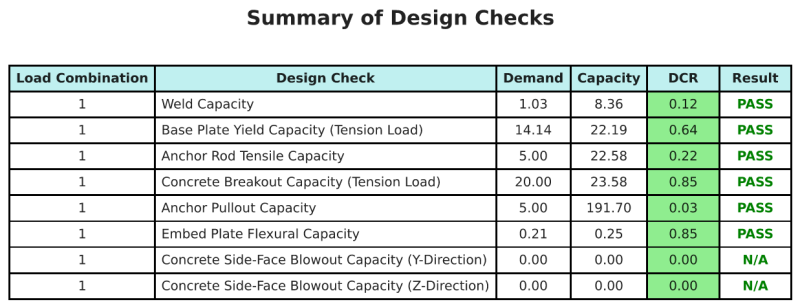
Résumé de la conception
Ce logiciel Logiciel de conception de plaques de base Skyciv peut générer automatiquement un rapport de calcul étape par étape pour cet exemple de conception. Il fournit également un résumé des contrôles effectués et de leurs ratios résultants, rendre les informations faciles à comprendre en un coup d'œil. Vous trouverez ci-dessous un échantillon de tableau de résumé, qui est inclus dans le rapport.
Rapport d'échantillon de skyciv
Découvrez le niveau de détail et de clarté que vous pouvez attendre d'un rapport de conception de plaque de base SkyCiv. Le rapport comprend toutes les vérifications de conception clés, équations, et les résultats présentés dans un format clair et facile à lire. Il est entièrement conforme aux normes de conception. Cliquez ci-dessous pour voir un exemple de rapport généré à l'aide du calculateur de plaque de base SkyCiv.
Logiciel d'achat de plaques de base
Achetez la version complète du module de conception de la plaque de base seul sans aucun autre module Skyviv. Cela vous donne un ensemble complet de résultats pour la conception de la plaque de base, y compris des rapports détaillés et plus de fonctionnalités.