Exemple de conception de plaque de base utilisant AISC 360-22 et ACI 318-19
Déclaration de problème
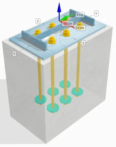
Déterminez si la connexion colonne-plaque de base conçue est suffisante pour 30 kN charge de traction, 3 kN Vy charge de cisaillement, et 6 kN Vz charge de cisaillement.
Données données
Colonne:
Section colonne: L14x30
Zone de colonne: 5709.7 mm2
Matériau de colonne: A992
Plaque de base:
Dimensions de la plaque de base: 250 millimètre x 250 mm
Épaisseur de plaque de base: 12 mm
Matériau de plaque de base: A992
Jointoyer:
Épaisseur de coulis: 0 mm
Béton:
Dimensions du béton: 300 millimètre x 500 mm
Épaisseur de béton: 500 mm
Matériau en béton: 20.7 MPa
Craquelé ou sans crates: Fissuré
Ancres:
Diamètre d'ancrage: 16 mm
Durée d'admission efficace: 400 mm
Fin de l'ancre: Plaque circulaire
Diamètre de la plaque intégrée: 70 mm
Épaisseur de plaque intégrée: 10 mm
Matériau en acier: F1554 Gr.55
Filetages dans le plan de cisaillement: Compris
Soudures:
Taille de soudure: 7 mm
Classification du métal de remplissage: E70XX
Ancrer les données (de Calculateur de skyciv):
Modèle dans l'outil gratuit SkyCiv
Modélisez la conception de la plaque de base ci-dessus à l'aide de notre outil en ligne gratuit dès aujourd'hui.! Aucune inscription requise.
Remarque
Le but de cet exemple de conception est de démontrer les calculs étape par étape pour les contrôles de capacité impliquant des charges de cisaillement et axiales simultanées.. Certaines des vérifications requises ont déjà été abordées dans les exemples de conception précédents.. Veuillez vous référer aux liens fournis dans chaque section.
Calculs étape par étape
Vérifier #1: Calculer la capacité de soudure
Pour déterminer la capacité de soudure sous chargement simultané, nous devons d'abord calculer la demande de soudure en raison du charge de cisaillement et la demande de soudure en raison du charge de traction. Vous pouvez vous référer à ceci lien pour la procédure permettant d'obtenir les exigences de soudure en cisaillement, et ça lien pour les demandes de soudure par tension.
Pour cette conception, l' demande de soudure sur le Web en raison de la charge de tension, on constate que, où le stress est exprimé comme force par unité de longueur.
\(r_{u,\texte{la toile}} = frac{T_{u,\texte{ancre}}}{l_{\texte{eff}}} = frac{5\ \texte{kN}}{93.142\ \texte{mm}} = 0.053681\ \texte{kN / mm}\)
en outre, l' contrainte de soudure à n'importe quelle partie de la section de poteau due à la charge de cisaillement est déterminée comme:
\(v_{ouais} = frac{V_y}{L_{\texte{souder}}} = frac{3\ \texte{kN}}{1250.7\ \texte{mm}} = 0.0023987\ \texte{kN / mm}\)
\(v_{à} = frac{V_z}{L_{\texte{souder}}} = frac{6\ \texte{kN}}{1250.7\ \texte{mm}} = 0.0047973\ \texte{kN / mm}\)
Puisqu’il existe une combinaison de charges de traction et de cisaillement au niveau la toile, nous devons obtenir la résultante. Exprimer cela en force par unité de longueur, nous avons:
\(r_u = sqrt{(r_{u,\texte{la toile}})^ 2 + (v_{ouais})^ 2 + (v_{à})^ 2}\)
\(r_u = sqrt{(0.053681\ \texte{kN / mm})^ 2 + (0.0023987\ \texte{kN / mm})^ 2 + (0.0047973\ \texte{kN / mm})^ 2}\)
\(r_u = 0.053949\ \texte{kN / mm}\)
Pour le brides, seules les contraintes de cisaillement sont présentes. C'est à dire, la résultante est:
\(r_u = sqrt{(v_{ouais})^ 2 + (v_{à})^ 2}\)
\(r_u = sqrt{(0.0023987\ \texte{kN / mm})^ 2 + (0.0047973\ \texte{kN / mm})^ 2} = 0.0053636\ \texte{kN / mm}\)
Prochain, on calcule le capacités de soudure. Pour la bride, nous déterminons l'angle θ en utilisant le Vz et Vy de charges.
\( \thêta = tan^{-1}\!\la gauche(\frac{v_{ouais}}{v_{à}}\droite) = tan^{-1}\!\la gauche(\frac{0.0023987\ \texte{kN / mm}}{0.0047973\ \texte{kN / mm}}\droite) = 0.46365\ \texte{travailler} \)
par conséquent, l' kds le facteur et la capacité de soudure sont calculés à l'aide de AISC 360-22 Eq. J2-5 et Eq. J2-4.
\(afin que les ingénieurs puissent revoir exactement comment ces calculs sont effectués{ds} = 1.0 + 0.5(\sin(\thêta ))^{1.5} = 1 + 0.5 \fois (\sin(0.46365\ \texte{travailler}))^{1.5} = 1.1495\)
\(\phi r_{n,flg} = phi,0,6,F_{Exx}\,E_w,k_{ds} = 0.75 \fois 0.6 \fois 480\ \texte{MPa} \fois 4.95\ \texte{mm} \fois 1.1495 = 1.2291\ \texte{kN / mm}\)
Pour le web, nous calculons l'angle θ en utilisant une formule différente. Noter que Ouah est utilisé dans la formule car il représente la charge parallèle à l'axe de la soudure.
\( \thêta = cos^{-1}\!\la gauche(\frac{v_{ouais}}{r_u}\droite) = cos^{-1}\!\la gauche(\frac{0.0023987\ \texte{kN / mm}}{0.053949\ \texte{kN / mm}}\droite) = 1.5263\ \texte{travailler} \)
En utilisant AISC 360-22 Eq. J2-5 et Eq. J2-4, l' kds Le facteur et la capacité de soudure résultante sont déterminés de la même manière.
\(afin que les ingénieurs puissent revoir exactement comment ces calculs sont effectués{ds} = 1.0 + 0.5(\sin(\thêta ))^{1.5} = 1 + 0.5 \fois (\sin(1.5263\ \texte{travailler}))^{1.5} = 1.4993\)
\(\phi r_{n,la toile} = phi,0,6,F_{Exx}\,E_w,k_{ds} = 0.75 \fois 0.6 \fois 480\ \texte{MPa} \fois 4.95\ \texte{mm} \fois 1.4993 = 1.603\ \texte{kN / mm}\)
dernièrement, nous effectuons contrôles des métaux communs pour la colonne et la plaque de base, puis obtenez la capacité régissant les métaux de base.
\( \phi r_{Nbm,col} = phi,0,6,F_{u,col}\,t_{col,moitié} = 0.75 \fois 0.6 \fois 448.2\ \texte{MPa} \fois 3.429\ \texte{mm} = 0.6916\ \texte{kN / mm} \)
\( \phi r_{Nbm,pb} = phi,0,6,F_{u,pb}\,t_{pb} = 0.75 \fois 0.6 \fois 400\ \texte{MPa} \fois 12\ \texte{mm} = 2.1595\ \texte{kN / mm} \)
\( \phi r_{Nbm} = mingros(\phi r_{Nbm,pb},\ \phi r_{Nbm,col}\grand) = min(2.1595\ \texte{kN / mm},\ 0.6916\ \texte{kN / mm}) = 0.6916\ \texte{kN / mm} \)
Nous comparons ensuite les capacités de soudage d'angle et capacités en métaux communs pour les exigences de soudure au brides et âme séparément.
Puisque 0.053949 kN / mm < 0.6916 kN / mm, La capacité de soudure est suffisant.
Vérifier #2: Calculer la capacité de rendement en flexion de la plaque de base due à la charge de tension
Un exemple de conception pour la capacité de flexion de la plaque de base est déjà abordé dans l'exemple de conception de plaque de base pour la traction.. Veuillez vous référer à ce lien pour le calcul étape par étape.
Vérifier #3: Calculer la capacité de traction de la tige d'ancrage
Un exemple de conception pour la capacité de traction de la tige d'ancrage est déjà abordé dans l'exemple de conception de plaque de base pour la tension.. Veuillez vous référer à ce lien pour le calcul étape par étape. Veuillez vous référer à ce lien pour le calcul étape par étape.
Vérifier #4: Calculer la capacité de rupture du béton en tension
Un exemple de conception pour la capacité du béton à se rompre en traction est déjà discuté dans l'exemple de conception de plaque de base pour la traction.. Veuillez vous référer à ce lien pour le calcul étape par étape. Veuillez vous référer à ce lien pour le calcul étape par étape.
Vérifier #5: Calculer la capacité d'arrachement de l'ancre
Un exemple de conception pour la capacité d'extraction de l'ancre est déjà abordé dans l'exemple de conception de plaque de base pour la tension.. Veuillez vous référer à ce lien pour le calcul étape par étape. Veuillez vous référer à ce lien pour le calcul étape par étape.
Vérifier #6: Calculer la capacité de flexion de la plaque intégrée
Un exemple de conception pour le contrôle supplémentaire de la capacité de flexion de la plaque encastrée est déjà discuté dans l'exemple de conception de plaque de base pour la traction.. Veuillez vous référer à ce lien pour le calcul étape par étape.
Vérifier #7: Calculer la capacité d'éruption de la face latérale dans la direction en y
Pour calculer le Éruption latérale (SFBO) capacité, nous déterminons d'abord le total force de tension sur les ancrages les plus proches du bord. Pour ce chèque, nous évaluerons la capacité du bord le long du Direction Y.
Étant donné que les projections du cône de rupture du SFBO le long de la direction Y se chevauchent, les ancres sont traitées comme un groupe d'ancrage.
La demande de tension totale du groupe d'ancrage est calculée comme suit ::
\(N_{faire} = gauche(\frac{N_x}{n_{a,t}}\droite) n_{Y,G1} = gauche(\frac{30\ \texte{kN}}{6}\droite) \fois 3 = 15\ \texte{kN}\)
Prochain, Nous déterminons le distances aux bords:
\(c_{z,\min} = min(c_{\texte{la gauche},G1},\ c_{\texte{droite},G1}) = min(100\ \texte{mm},\ 200\ \texte{mm}) = 100\ \texte{mm}\)
\(c_{Y,\min} = min(c_{\texte{Haut},G1},\ c_{\texte{bas},G1}) = min(150\ \texte{mm},\ 150\ \texte{mm}) = 150\ \texte{mm}\)
Utilisation de ces distances aux bords, on calcule le capacité du groupe d'ancrage conformément à ACI 318-19 Eq. (17.6.4.1).
\(N_{comme} = gauche(\frac{1 + \dfrac{c_{Y,\min}}{c_{z,\min}}}{4} + \frac{s_{somme,Y,G1}}{6\,c_{z,\min}}\droite)\fois 13 \fois gauche(\frac{c_{z,\min}}{1\ \texte{mm}}\droite)\fois sqrt{\frac{UNE_{brg}}{\texte{mm}^ 2}}\ \lambda_a sqrt{\frac{f_c}{\texte{MPa}}}\fois 0.001\ \texte{kN}\)
\(N_{comme} = gauche(\frac{1 + \dfrac{150\ \texte{mm}}{100\ \texte{mm}}}{4} + \frac{200\ \texte{mm}}{6\fois 100\ \texte{mm}}\droite)\fois 13 \fois gauche(\frac{100\ \texte{mm}}{1\ \texte{mm}}\droite)\fois sqrt{\frac{3647.4\ \texte{mm}^ 2}{1\ \texte{mm}^ 2}}\fois 1 \fois sqrt{\frac{20.68\ \texte{MPa}}{1\ \texte{MPa}}}\fois 0.001\ \texte{kN}\)
\(N_{comme} = 342.16\ \texte{kN}\)
Dans l'équation originale, un facteur de réduction est appliqué lorsque l'espacement des ancrages est inférieur à 6ca₁, en supposant que les ancrages à tête ont une distance de bord suffisante. Par contre, dans cet exemple de conception, puisque ca₂ < 3ca₁, le calculateur SkyCiv applique un facteur de réduction supplémentaire pour tenir compte de la capacité de pointe réduite.
Ensuite, l' capacité de conception SFBO est:
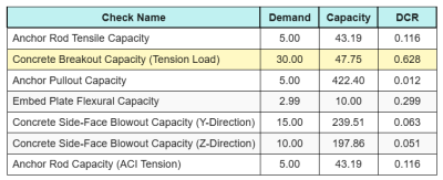
\(\phi N_{comme} = phi,N_{comme} = 0.7 \fois 342.16\ \texte{kN} = 239.51\ \texte{kN}\)
Puisque 15 kN < 239.51 kN, la capacité SFBO le long de la direction Y est suffisant.
Vérifier #8: Calculer la capacité d'éruption de la face latérale dans la direction z
En suivant la même approche que dans Vérifier #7, la demande de tension totale du groupe d'ancrage pour les ancrages les plus proches du Direction Z le bord est:
\(N_{faire} = gauche(\frac{N_x}{n_{a,t}}\droite)n_{z,G1} = gauche(\frac{30\ \texte{kN}}{6}\droite)\fois 2 = 10\ \texte{kN}\)
Ce logiciel distances aux bords sont calculés comme:
\(c_{Y,\min} = min(c_{\texte{Haut},G1},\ c_{\texte{bas},G1}) = min(150\ \texte{mm},\ 350\ \texte{mm}) = 150\ \texte{mm}\)
\(c_{z,\min} = min(c_{\texte{la gauche},G1},\ c_{\texte{droite},G1}) = min(100\ \texte{mm},\ 100\ \texte{mm}) = 100\ \texte{mm}\)
Ce logiciel capacité nominale SFBO est alors déterminé comme:
\(N_{comme} = gauche(\frac{1 + \dfrac{c_{z,\min}}{c_{Y,\min}}}{4} + \frac{s_{somme,z,G1}}{6\,c_{Y,\min}}\droite)\fois 13 \fois gauche(\frac{c_{Y,\min}}{1\ \texte{mm}}\droite)\fois sqrt{\frac{UNE_{brg}}{\texte{mm}^ 2}}\ \lambda_a sqrt{\frac{f_c}{\texte{MPa}}}\fois 0.001\ \texte{kN}\)
\(N_{comme} = gauche(\frac{1 + \dfrac{100\ \texte{mm}}{150\ \texte{mm}}}{4} + \frac{100\ \texte{mm}}{6\fois 150\ \texte{mm}}\droite)\fois 13 \fois gauche(\frac{150\ \texte{mm}}{1\ \texte{mm}}\droite)\fois sqrt{\frac{3647.4\ \texte{mm}^ 2}{1\ \texte{mm}^ 2}}\fois 1 \fois sqrt{\frac{20.68\ \texte{MPa}}{1\ \texte{MPa}}}\fois 0.001\ \texte{kN}\)
\(N_{comme} = 282.65\ \texte{kN}\)
Depuis la distance au bord ca₂ est encore inférieur à 3ca₁, le même facteur de réduction modifié est appliqué.
Ensuite, l' capacité de conception SFBO est:
\(\phi N_{comme} = phi,N_{comme} = 0.7 \fois 282.65\ \texte{kN} = 197.86\ \texte{kN}\)
Puisque 10 kN < 197.86 kN, la capacité SFBO le long de la Direction Z est suffisant.
Vérifier #9: Calculer la capacité de répartition (Vy Shear)
Un exemple de conception pour la capacité d'arrachement du béton en cisaillement Vy est déjà abordé dans l'exemple de conception de plaque de base pour le cisaillement.. Veuillez vous référer à ce lien pour le calcul étape par étape.
Vérifier #10: Calculer la capacité de répartition (Cisaillement vz)
Un exemple de conception pour la capacité d'arrachement du béton en cisaillement Vy est déjà abordé dans l'exemple de conception de plaque de base pour le cisaillement.. Veuillez vous référer à ce lien pour le calcul étape par étape.
Vérifier #11: Calculer la capacité d'extraction (Vy Shear)
Un exemple de conception de la capacité du béton à résister à la rupture par effet de levier due au cisaillement Vy est déjà abordé dans l'exemple de conception de plaque de base pour le cisaillement.. Veuillez vous référer à ce lien pour le calcul étape par étape.
Vérifier #12: Calculer la capacité d'extraction (Cisaillement vz)
Un exemple de conception de la capacité du béton à résister à la rupture par effet de levier due au cisaillement Vy est déjà abordé dans l'exemple de conception de plaque de base pour le cisaillement.. Veuillez vous référer à ce lien pour le calcul étape par étape.
Vérifier #13: Calculer la capacité de cisaillement de la tige d'ancrage
Un exemple de conception pour la capacité de cisaillement de la tige d'ancrage est déjà abordé dans l'exemple de conception de plaque de base pour le cisaillement.. Veuillez vous référer à ce lien pour le calcul étape par étape.
Vérifier #14: Calculer le cisaillement de la tige d'ancrage et la capacité axiale (AISC)
Pour déterminer la capacité de la tige d'ancrage sous des charges combinées de cisaillement et axiales, nous utilisons AISC 360-22 Eq. J3-3A. Dans cette calculatrice, l'équation est réorganisée pour exprimer le résultat sous la forme de la résistance au cisaillement modifiée..
Ce logiciel demande de cisaillement est défini comme le charge de cisaillement par ancrage.
\(V_{faire} = V_{faire} = 2.5\ \texte{kN}\)
Ce logiciel demande de tension s'exprime comme le contrainte de traction dans la tige d'ancrage.
\(F_{Utah} = frac{N_{faire}}{UNE_{canne à pêche}} = frac{5\ \texte{kN}}{201.06\ \texte{mm}^ 2} = 24.868\ \texte{MPa}\)
Ce logiciel capacité de cisaillement modifiée de la tige d'ancrage est alors calculé comme:
\(F’_{nv} = min!\la gauche(1.3\,F_{nv} – \la gauche(\frac{F_{nv}}{\Phi f_{NT}}\droite) F_{Utah},\; F_{nv}\droite)\)
\(F’_{nv} = min!\la gauche(1.3\fois 232.69\ \texte{MPa} – \la gauche(\frac{232.69\ \texte{MPa}}{0.75\fois 387.82\ \texte{MPa}}\droite)\fois 24.868\ \texte{MPa},\; 232.69\ \texte{MPa}\droite) = 232.69\ \texte{MPa}\)
On multiplie ensuite cette force par le zone d'ancrage utilisant AISC 360-22 Eq. J3-2.
\(\phi R_{n,\texte{AISC}} = phi F'_{nv} UNE_{\texte{canne à pêche}} = 0.75 \fois 232.69\ \texte{MPa} \fois 201.06\ \texte{mm}À partir de l'élévation du sol générée à partir des élévations Google 35.09\ \texte{kN}\)
Puisque 2.5 kN < 35.09 kN, la capacité de la tige d'ancrage est suffisant.
Vérifier #15: Calculer les contrôles d'interaction (ACI)
Lors de la vérification de la capacité de la tige d'ancrage sous des charges combinées de cisaillement et de traction à l'aide de ACI, une approche différente est appliquée. Pour être complet, nous effectuons également le Vérifications des interactions ACI dans ce calcul, qui incluent d'autres contrôles d'interactions concrètes ainsi que.
Voici le résultat ratios pour tous les contrôles de tension ACI:
Et voici le résultat ratios pour tous les contrôles de cisaillement ACI:
Nous obtenons le chèque avec le rapport le plus élevé et le comparons au rapport d'interaction maximal en utilisant ACI 318-19 Eq. 17.8.3.
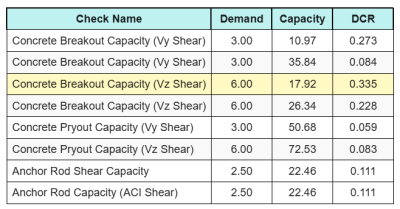
\(JE_{int} = frac{N_{faire}}{\phi N_n} + \frac{V_{faire}}{\phi V_n} = frac{30}{47.749} + \frac{6}{17.921} = 0.96308\)
Puisque 0.96 < 1.2, le contrôle d'interaction est suffisant.
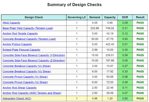
Résumé de la conception
Ce logiciel Logiciel de conception de plaques de base Skyciv peut générer automatiquement un rapport de calcul étape par étape pour cet exemple de conception. Il fournit également un résumé des contrôles effectués et de leurs ratios résultants, rendre les informations faciles à comprendre en un coup d'œil. Vous trouverez ci-dessous un échantillon de tableau de résumé, qui est inclus dans le rapport.
Rapport d'échantillon de skyciv
Découvrez le niveau de détail et de clarté que vous pouvez attendre d'un rapport de conception de plaque de base SkyCiv. Le rapport comprend toutes les vérifications de conception clés, équations, et les résultats présentés dans un format clair et facile à lire. Il est entièrement conforme aux normes de conception. Cliquez ci-dessous pour voir un exemple de rapport généré à l'aide du calculateur de plaque de base SkyCiv.
Logiciel d'achat de plaques de base
Achetez la version complète du module de conception de la plaque de base seul sans aucun autre module Skyviv. Cela vous donne un ensemble complet de résultats pour la conception de la plaque de base, y compris des rapports détaillés et plus de fonctionnalités.