Dans cet article, nous vous expliquerons comment déterminer les catégories de terrain ou d'exposition du côté au vent de l'emplacement du site., qui sont essentiels pour calculer les charges de vent. Nous couvrirons les procédures spécifiques décrites dans l'ASCE 7, CNBC 2015, et AS / NZS 1170.2 pour déterminer les catégories de terrain et discuter de la manière dont celles-ci s'appliquent à chaque code de référence disponible dans le générateur de charge SkyCiv.
ASCE7-16/ASCE 7-22
Pour ASCE 7, la procédure pour déterminer la catégorie d'exposition de l'exposition au vent d'un emplacement de site est discutée dans la section 26.7, en fonction du terrain. Dans cet article, pour simplifier la référence, nous utiliserons ASCE 7-16. Pour chaque direction de source de vent, il doit être analysé à partir de deux secteurs au vent s'étendant sur ±45°.
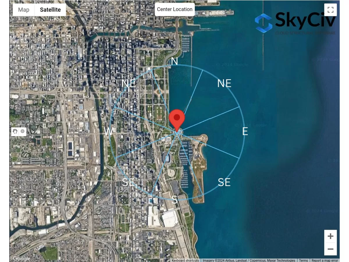
Figure 1. Secteurs de terrain pour chaque direction de source de vent.
Pour chaque secteur, la catégorie de rugosité de surface doit être vérifiée sur la base de la définition suivante basée sur la section 26.7.2 de l'ASCE 7-16:
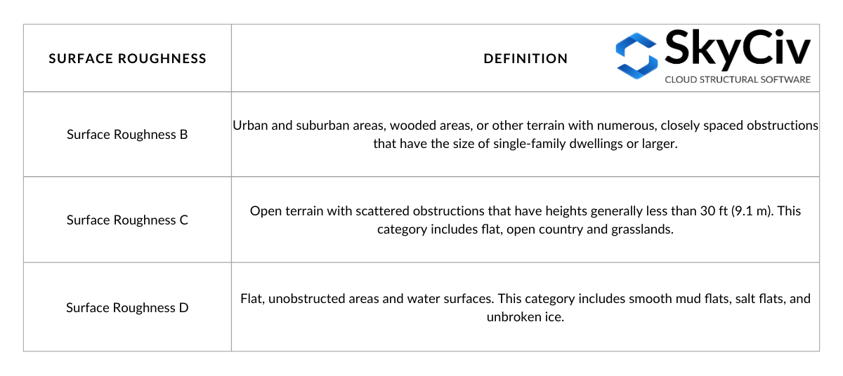
Le tableau 1. Définition de la rugosité de surface basée sur la section 26.7.2 de l'ASCE 7-16.
De la définition de la rugosité de surface, nous pouvons déterminer la catégorie d'exposition du terrain délimité par le secteur au vent. La définition de chaque catégorie d'exposition est indiquée dans la section 26.7.3 de l'ASCE 7-16 comme suit:
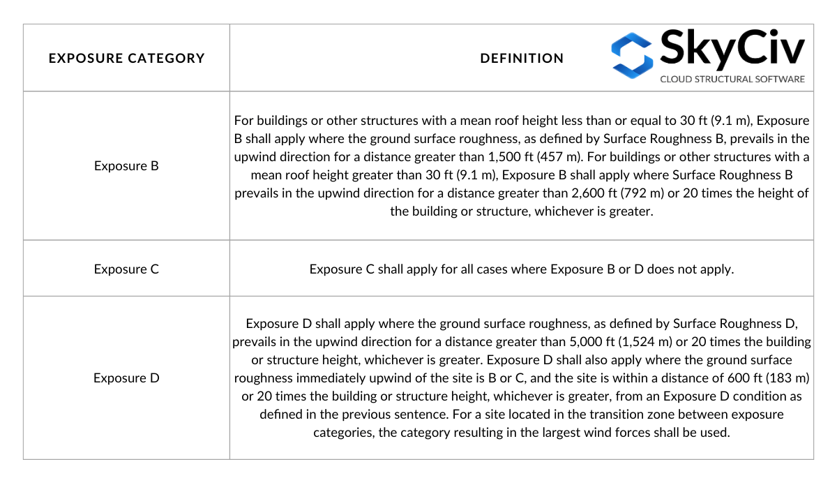
Le tableau 2. Définition de la catégorie d'exposition basée sur la section 26.7.3 de l'ASCE 7-16.
Le tableau 2 peut être visualisé à travers les figures suivantes basées sur la figure C26.7-2:
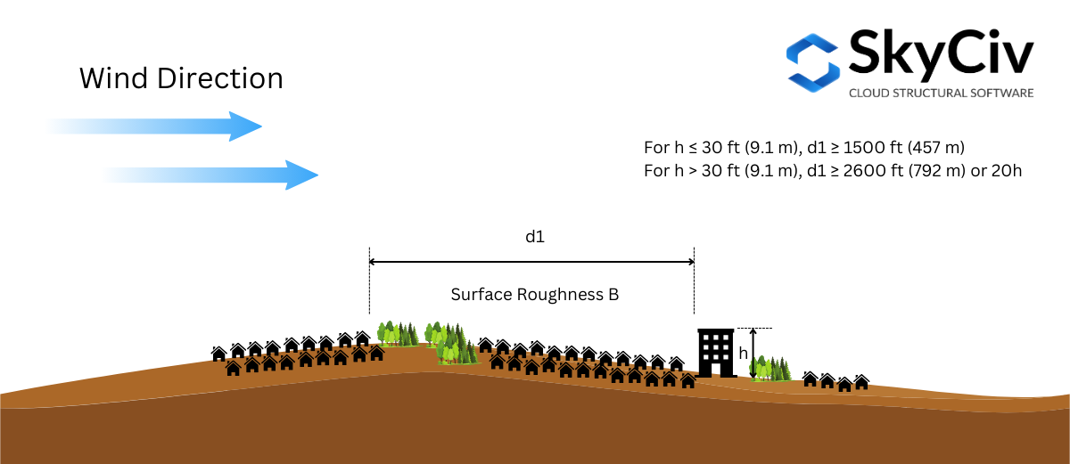
Figure 2. Conditions de rugosité de surface au vent requises pour l’exposition B.
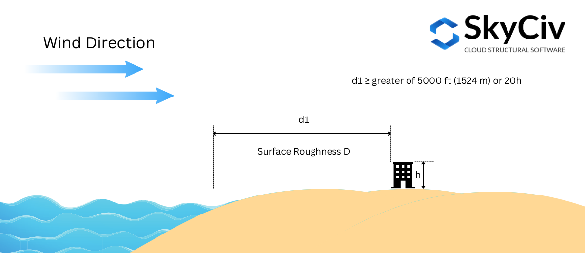
Figure 3. Condition de rugosité de surface au vent requise pour l’exposition D – Cas 1.
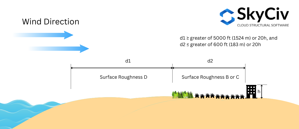
Figure 4. Condition de rugosité de surface au vent requise pour l’exposition D – Cas 2.
La catégorie d'exposition doit être déterminée pour chaque direction de la source de vent.. Utilisation d'un exemple d'emplacement de site – “1200 S DuSable Lake Shore Dr, Chicago, LES 60605, États-Unis”, analysons cela pour chaque direction.
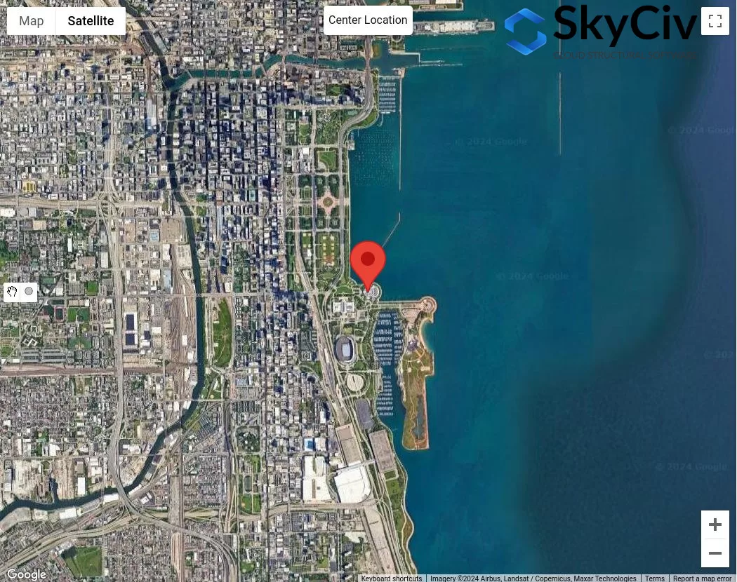
Figure 4. Emplacement de l'échantillon pour l'analyse de la catégorie d'exposition.
En supposant que la hauteur moyenne du toit de la structure est 25 pi ( \( 20h = 500 pi \)), nous utiliserons la procédure suivante pour vérifier la catégorie d'exposition pour chaque secteur:
État 1. Déterminez si l’exposition D à l’aide de la figure 3:
Utilisation de la figure 3 – où la distance \( ré_{1} \) est 5000 pi (1524 m), nous devons vérifier l'exposition D, où la rugosité de surface D est dominante pour l'ensemble 5000 étirement des pieds:
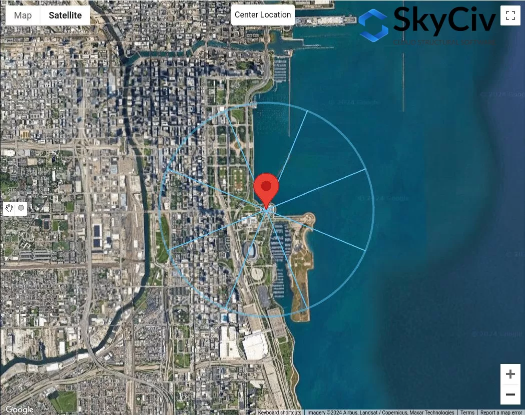
Figure 5. Distance de décalage de 5000 ft de l'emplacement du site pour la vérification de l'exposition D à l'aide de la figure 3.
De la figure 5, nous pouvons déjà conclure que les directions de la source du vent N, NE, et E avoir une rugosité de surface D pour l'ensemble 5000 étirement des pieds. Par conséquent, ces directions de source de vent sont Exposition D.
État 2. Déterminez si l’exposition D à l’aide de la figure 2
Utilisation de la figure 4 – où la distance \( ré_{1} \) est 5000 pi (1524 m) et la distance \( ré_{2} \) est égal à 600 pi (183 m), nous devons vérifier l'exposition D. De la figure 5, cela ne peut être appliqué que pour la direction de la source de vent venant du SE:
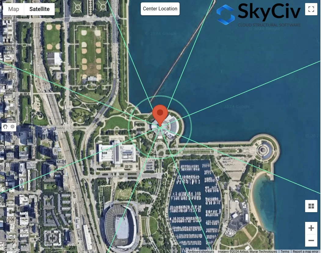
Figure 6. Distance de décalage de 600 pieds et supplémentaire 5000 ft de l'emplacement du site pour la vérification de l'exposition D à l'aide de la figure 4.
Pour la direction de la source de vent SE, utilisant \( ré_{2} = 600 pi \), on peut considérer que cette section est la rugosité de surface B. Par contre, pour la distance \( ré_{1} = 5000 pi \), la section n'est pas 100% Rugosité de surface D. Donc, SE ne doit pas être considéré comme une exposition D.
État 3. Déterminez si l’exposition B à l’aide de la figure 1
Utilisation de la figure 3 – où la distance \( ré_{1} \) est 1500 pi (457 m) puisque \( h < 30 pi \), nous devons vérifier l'exposition B.
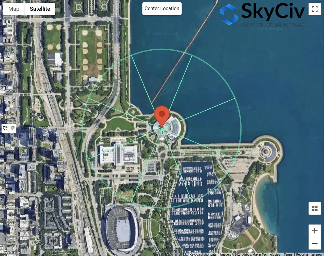
Figure 7. Distance de décalage de 1500 ft de l'emplacement du site pour la vérification de l'exposition B à l'aide de la figure 3.
De la figure 7, nous pouvons déterminer que pour les directions de la source du vent NW, W, SW, et S sont classés comme exposition B car la rugosité de surface pour chaque secteur de direction est la rugosité de surface B..
État 4. Si les conditions 1 à 3 ne sont pas vrais, donc, le terrain est l'exposition C.
Par conséquent, pour la direction de la source de vent SE, il est classé dans la catégorie d'exposition C. En résumé, les catégories d'exposition pour chaque direction de la source de vent sont indiquées dans la figure 8 ci-dessous.
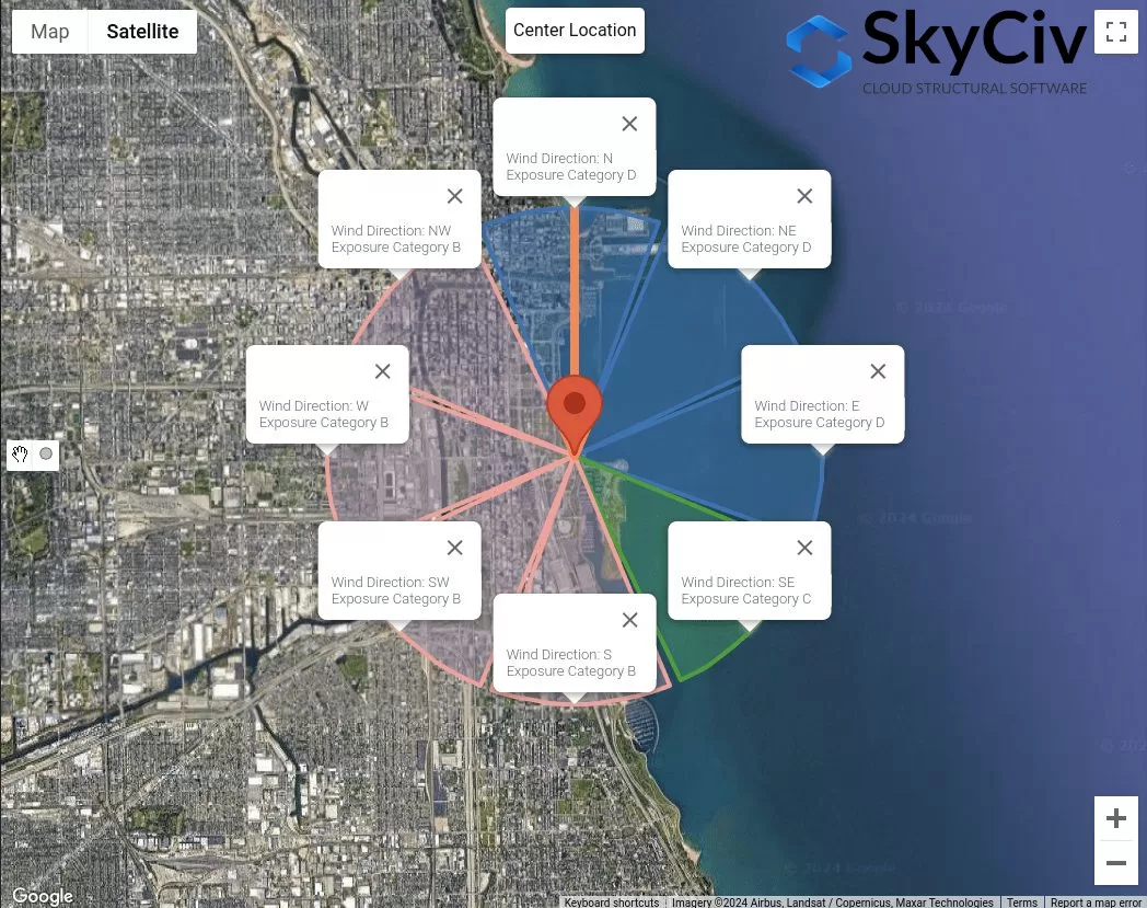
Figure 8. Les catégories d'exposition pour chaque direction de source de vent.
Ces données peuvent être utilisées pour déterminer quelle sera la pire direction de la source de vent en tant que coefficients de pression-vitesse. \( K_{z} \), Facteur Topographique \( K_{t} \), et facteur d'effet de rafale \( g \) utilisant un calcul détaillé sont affectés par la catégorie d'exposition.
CNBC 2015/2020
Pour le NBCC 2015, la procédure pour déterminer la catégorie d'exposition de l'exposition au vent d'un emplacement de site est discutée dans la section 4.1.7.3(5), en fonction du terrain. Pour chaque direction de source de vent, il doit être analysé à partir de deux secteurs au vent s'étendant sur ±45°.
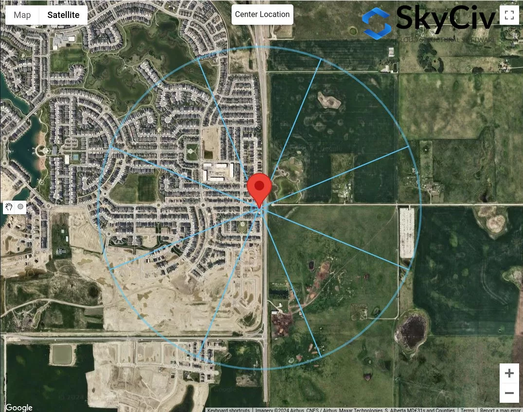
Figure 9. Secteurs de terrain pour chaque direction de source de vent.
Pour chaque secteur, la catégorie de terrain doit être vérifiée sur la base de la définition suivante basée sur la section 4.1.7.3(5) du NBCC 2015:
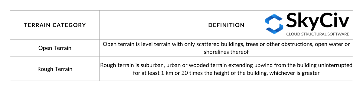
Le tableau 3. Définition des catégories de terrain telles que définies dans la section 4.1.7.3(5) du NBCC 2015.
Visualisation des options dans le tableau 3:
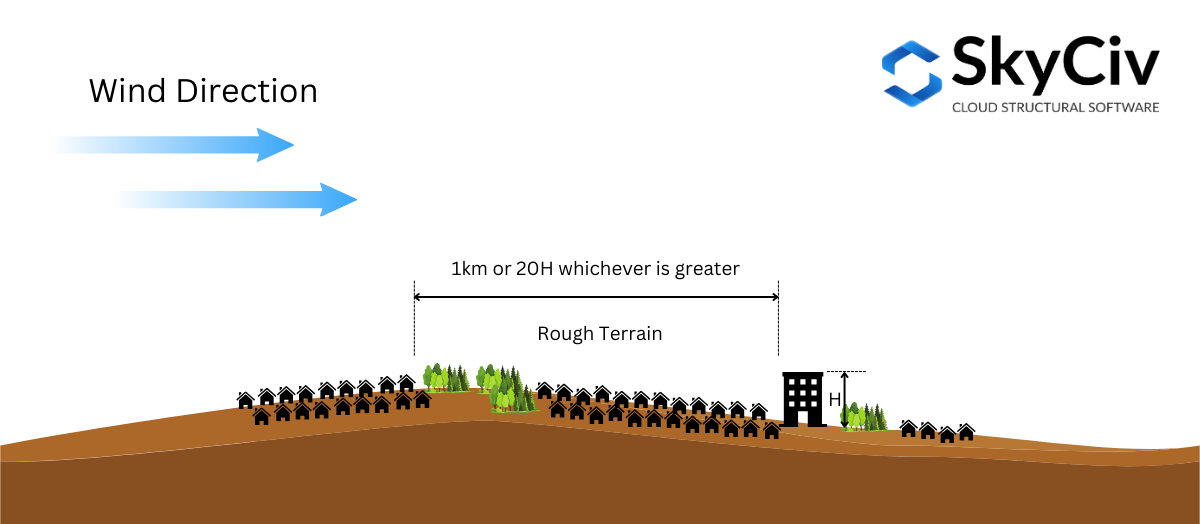
Figure 10. Définition du terrain accidenté telle que définie dans la section 4.1.7.3(5) du NBCC 2015.
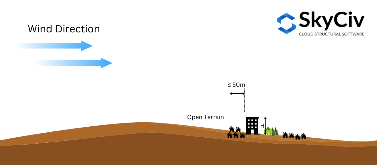
Figure 10. Définition du terrain ouvert telle que définie dans la section 4.1.7.3(5) du NBCC 2015.
Basé sur la section 4.1.7.3(5) du NBCC 2015, il est permis d'interpoler le Facteur d'exposition \( C_{e} \) en terrain intermédiaire. Si la distance en terrain accidenté de l'emplacement de la structure est supérieure ou égale à 1 km ou 20 fois la hauteur de la structure, selon la plus grande de ces deux valeurs, le terrain peut être considéré comme Terrain accidenté, et si la distance est inférieure à 50 m, il est considéré comme Terrain ouvert. Sinon, le facteur d'exposition \( C_{e} \) selon la section 4.1.7.3(5) sera calculé à partir des valeurs limites. Ceci peut être visualisé sur la figure 11 ci-dessous.
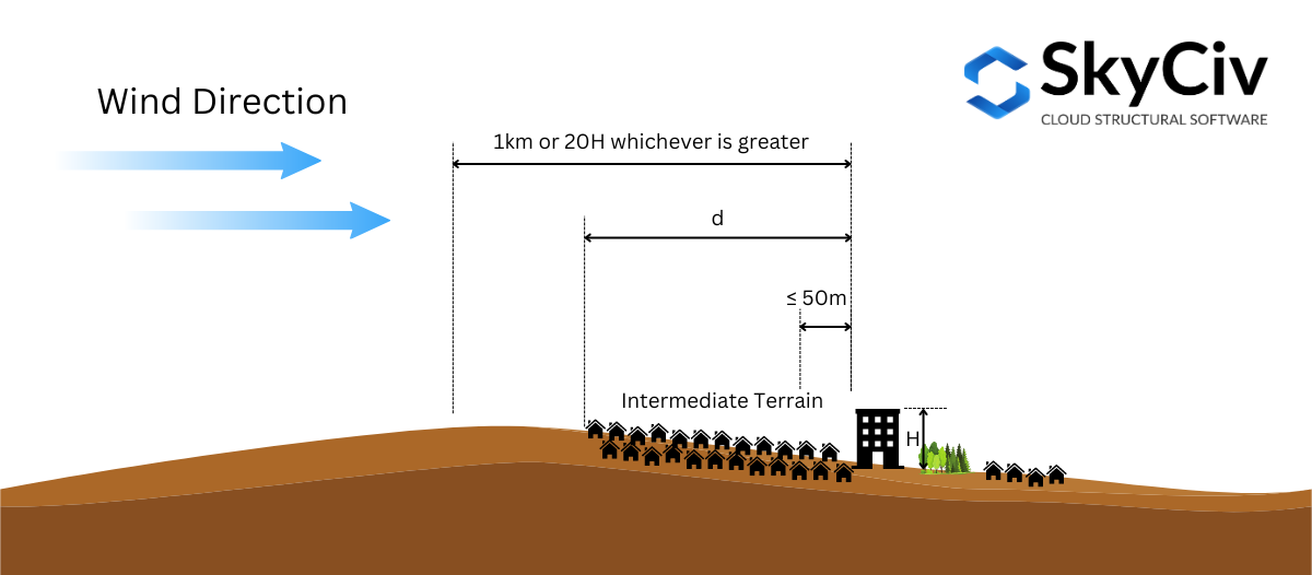
Figure 11. Définition du terrain intermédiaire telle que définie dans la section 4.1.7.3(5) du NBCC 2015.
Pour illustrer davantage cela, utilisons un exemple d'emplacement de site – “657 Masters Rd SE, Calgary, AB T3M 2B6, du Canada,” en supposant la hauteur de la structure \( H \) est 25 m ( \( 20H = 500 m \)).
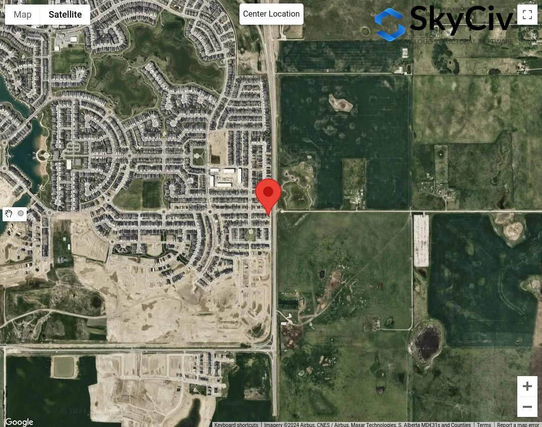
Figure 12. Exemple d'emplacement pour l'analyse de la catégorie de terrain.
La première étape consiste à classer les catégories évidentes de terrains accidentés et ouverts pour chaque direction de source de vent.. On peut tracer 50m et max de 1 km ou \( 20 H \) rayon de l'emplacement du site.
Figure 13. Distance de décalage de 50 m et 1 km pour déterminer la catégorie de terrain sur la base du tableau 1 définitions.
De la figure 13, on peut dire que les directions de la source du vent NE, E, et SE sont classés comme Terrain ouvert car la longueur du terrain accidenté pour chaque direction est inférieure à 50 m de l'emplacement du site. De plus, pour les directions de la source du vent O et NO peut être classé comme terrain accidenté car la longueur du terrain accidenté pour ces directions est supérieure à 1 km. Pour la direction de la source du vent N, nous pouvons, de manière prudente, supposer que le terrain ouvert est dominant dans cette direction. Pour le reste, S et SW, nous pouvons conclure qu'il s'agit de terrains intermédiaires et nous devrons mesurer la distance entre le terrain accidenté et l'emplacement du site..
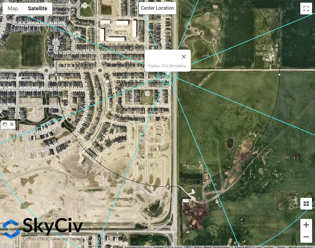
Figure 14. Longueur approximative du terrain accidenté mesurée à partir de l'emplacement du site pour une direction de la source de vent SO égale à 574 m.
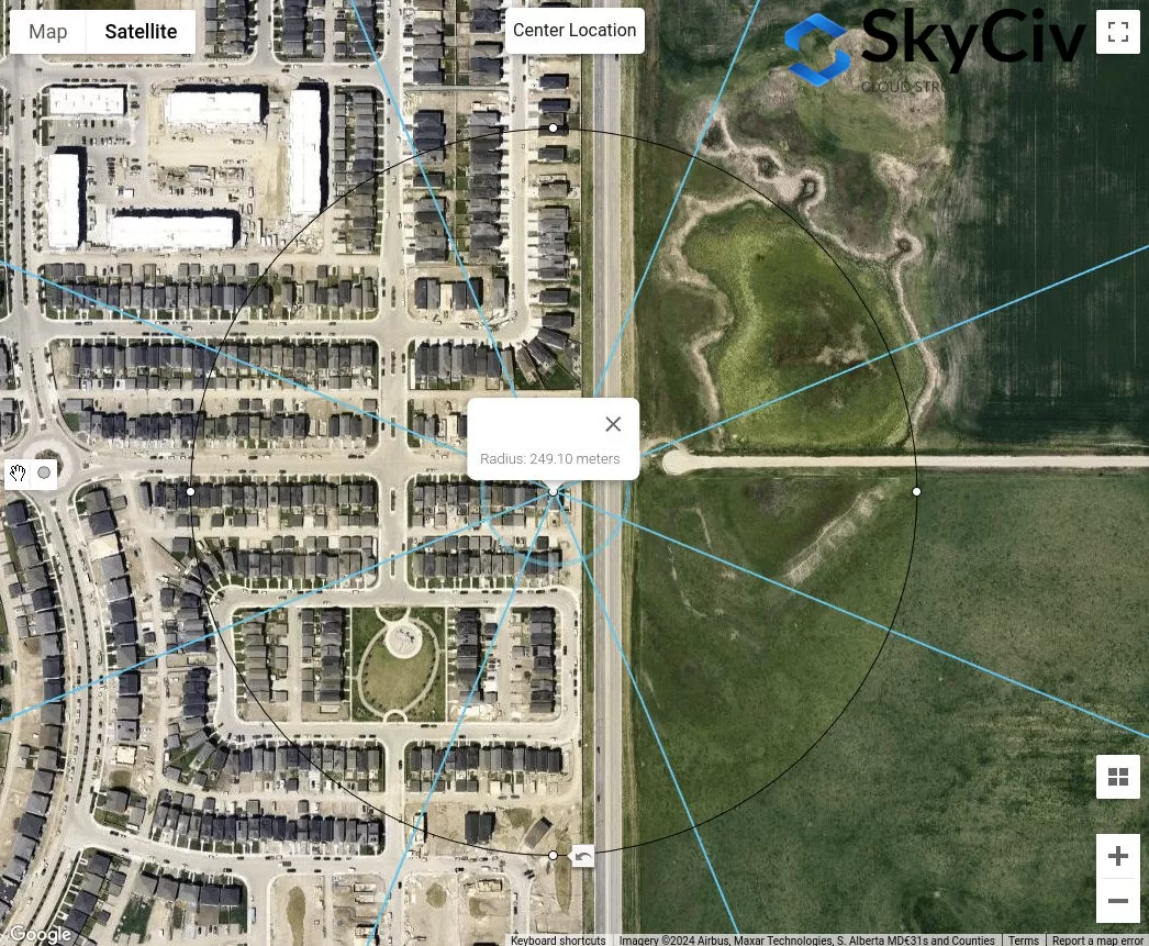
Figure 15. Longueur approximative du terrain accidenté mesurée à partir de l'emplacement du site pour une direction de source de vent S égale à 249 m.
D'après l'analyse ci-dessus, les directions de la source de vent avec Open Terrain donneront certainement des valeurs conservatrices. Par contre, si toutes les directions des sources de vent sont classées comme terrain intermédiaire, la procédure ci-dessus vous permet de déterminer la catégorie de terrain appropriée pour chaque direction..
AS / NZS 1170.2 (2021)
Pour AS / NZS 1170.2, la même procédure avec les références ci-dessus s'applique pour déterminer la catégorie de terrain de l'exposition au vent d'un emplacement de site. Ceci est discuté dans la section 4.2 d'AS / NZS 1170.2 (2021). Pour chaque direction de source de vent, il doit être analysé à partir de deux secteurs au vent s'étendant sur ±45°. La définition de chaque catégorie de terrain est présentée ci-dessous en fonction de la section 4.2.1 d'AS / NZS 1170.2 (2021):
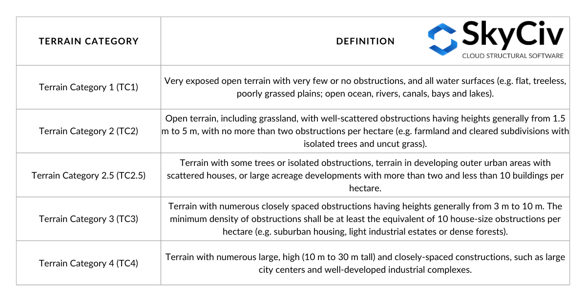
Le tableau 4. Définition des catégories de terrain telles que définies dans la section 4.2.1 d'AS / NZS 1170.2 (2021).
Pour déterminer la catégorie de terrain pour une direction, une distance de décalage égale à \( 20 z \) de l'emplacement de la structure doit être négligé. À partir de ce point, une distance décalée (distance moyenne) de 500 m ou \( 40 Avec), celui qui est le plus grand, doit être utilisé comme indiqué sur la figure 16 ci-dessous. Ce logiciel \( z \) la valeur est égale à la hauteur moyenne du toit, \( h \), lorsqu'il est inférieur ou égal à 25 m. Il est possible qu'à l'intérieur de cette distance moyenne, il y ait plusieurs catégories de terrain., et comme tel, une interpolation linéaire de doit être utilisée pour déterminer la \( M_{z,chat} \) en main, en fonction de la longueur de chaque catégorie de terrain, comme illustré sur la figure 4.1 d'AS / NZS 1170.2 (2021). Dans cet article, nous ne considérerons qu'une catégorie de terrain homogène dans la distance moyenne.
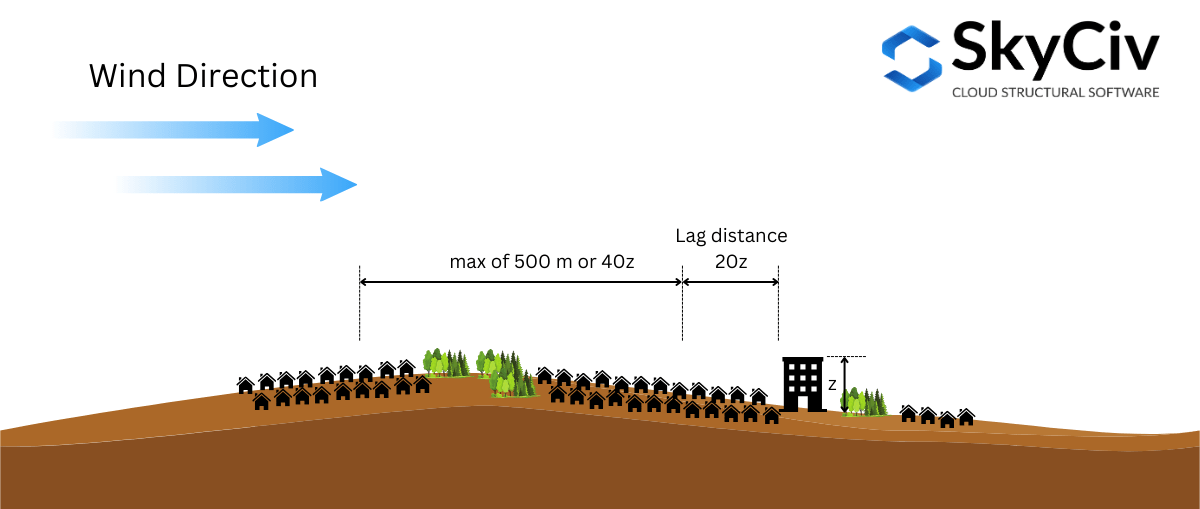
Figure 16. Illustration des distances utilisées pour déterminer la catégorie de terrain basée sur AS/NZS 1170.2 (2021).
Pour illustrer davantage cela, utilisons un exemple d'emplacement de site – latitude: 32°43’46″Argot: 151°31’47″E – en supposant la hauteur moyenne du toit \( h \) est 10 m ( où \( 20z = 20h = 200 m \) et \( 40z = 400 m \)).
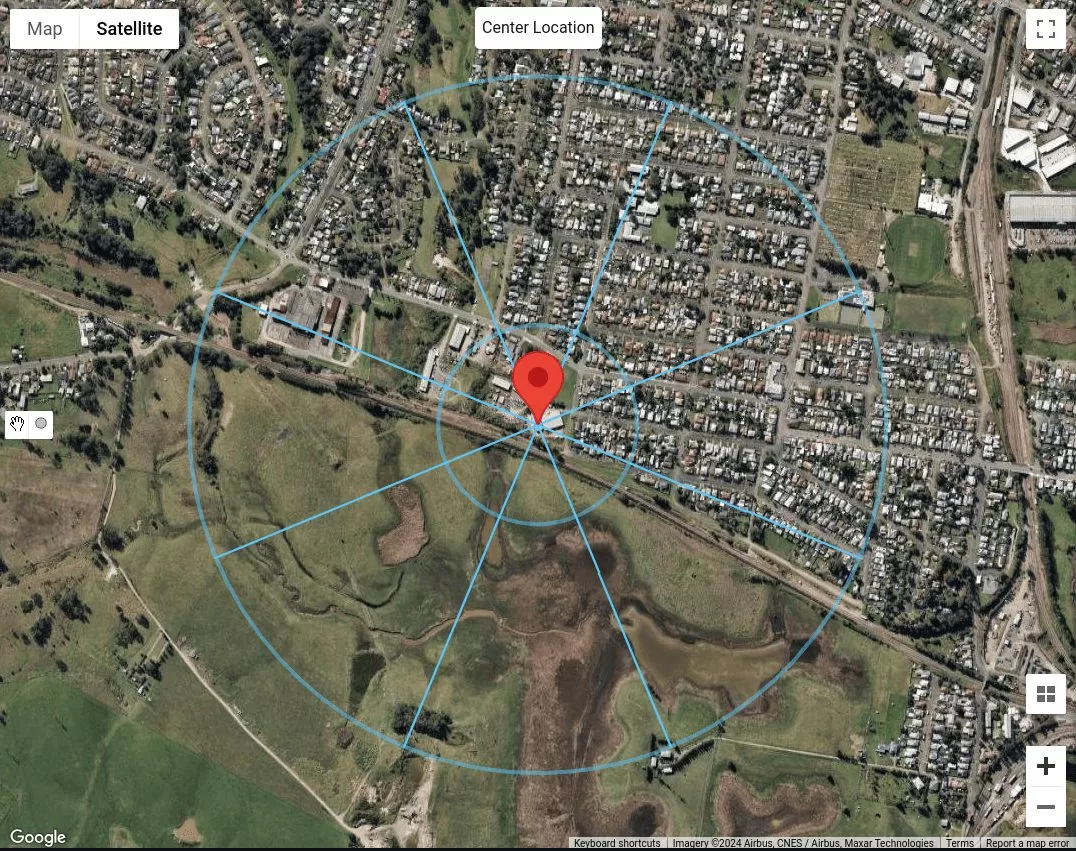
Figure 17. L'emplacement du site avec une distance de décalage égale à 200 m et une distance moyenne égale à 500 m pour chaque direction de la source de vent.
Puisque nous devons uniquement considérer la catégorie de terrain comme homogène sur l'ensemble des 500 m ou \( 40z \) distance, nous pouvons déjà classer chaque direction de source de vent. En supposant que les bâtiments sur N, NE et E, sont des bâtiments qui sont 5 à 10 m de haut, nous pouvons les classer dans la catégorie Terrain 3 (CT3) comme indiqué dans le tableau 4. Pour les directions de source de vent SE, S, SW, et W, puisque ce sont des plaines herbeuses sans obstacles, nous pouvons les classer dans la catégorie de terrain 1 (TC1). Ensuite, pour la direction de la source de vent NW, on peut en déduire qu'il y en a plus de deux mais moins de 10 bâtiments par hectare, avec des maisons dispersées. Par conséquent, nous pouvons classer cela dans la catégorie de terrain 2.5 (TC2.5).
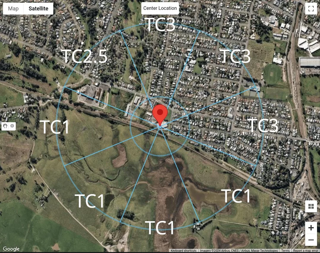
Figure 18. Résumé de la classification des catégories de terrain pour chaque direction de source de vent pour notre emplacement échantillon.
Utilisation du générateur de charge SkyCiv
Dans la version v4.7.0 du générateur de charge SkyCiv, de nouveaux outils cartographiques sont introduits – Mesurer la distance et Rayons de distance outils.
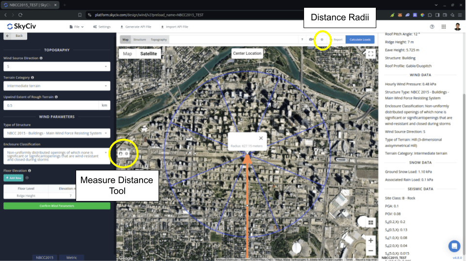
Figure 19. Outils de mesure de distance introduits dans SkyCiv Load Generator.
Ce logiciel Mesurer la distance l'outil est utilisé pour générer un cercle à partir d'un point cliqué sur la carte et afficher son rayon en mètres. Par ici, vous pouvez mesurer les distances entre l'emplacement analysé et certains emplacements. Ceci peut être utilisé pour mesurer dans NBCC 2015 pour le Étendue du terrain accidenté au vent utilisé pour calculer Facteur d'exposition \( C_{e} \). Cliquer sur le cercle généré le supprimera de la carte.
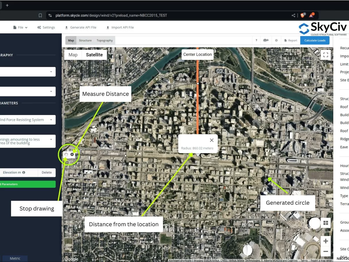
Figure 20. Outil de mesure de distance qui crée un décalage par rapport à l'emplacement et affiche le rayon/distance de décalage par rapport au centre introduit dans SkyCiv Load Generator.
En revanche, l' Rayons de distance est introduit afin que les utilisateurs puissent dessiner des cercles avec des distances spécifiées depuis l'emplacement pour chaque catégorie de source de vent. C'est un bouton bascule pour afficher ou masquer les rayons de distance sur la carte, avec l'emplacement du site comme centre des cercles.
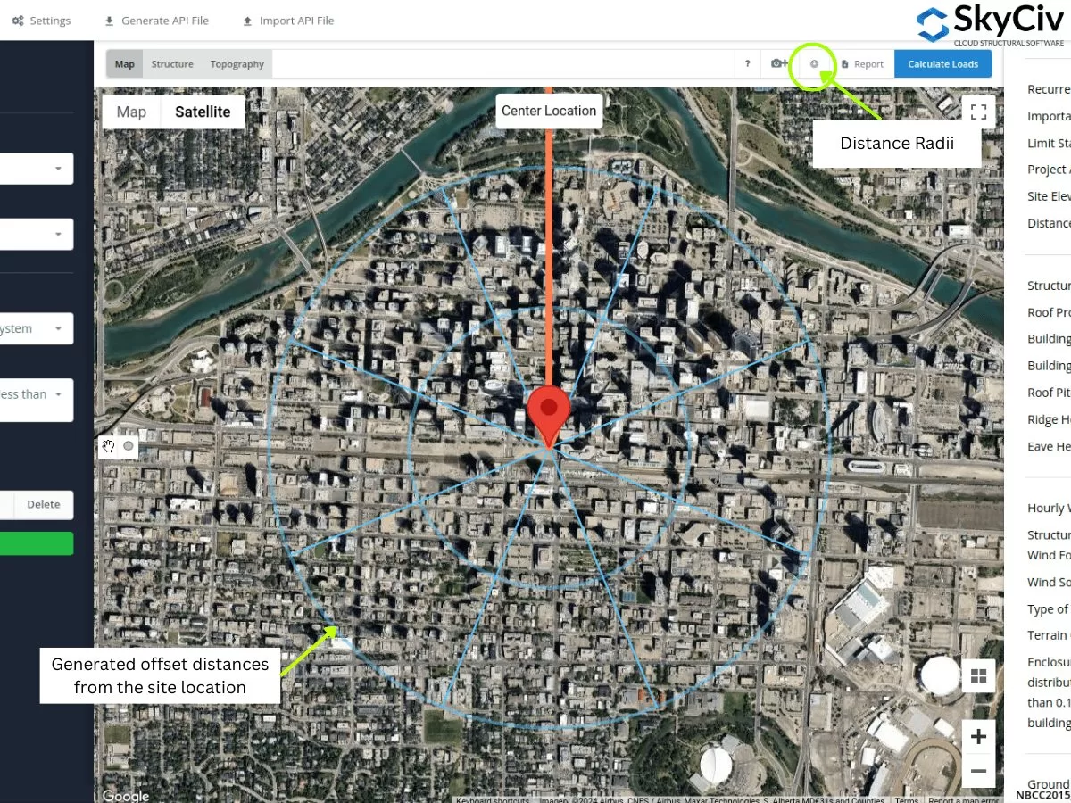
Figure 21. Outil de rayon de distance qui spécifiait les distances de décalage par rapport à l'emplacement du site introduit dans SkyCiv Load Generator.
Les valeurs des rayons peuvent être modifiées lors de l'ouverture des paramètres.
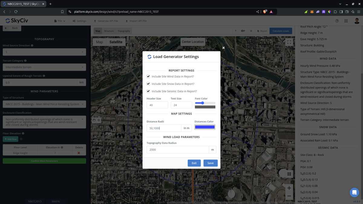
Figure 22. Option dans les paramètres pour modifier les distances pour l'outil Distance Radii dans SkyCiv Load Generator.
Notez que les utilisateurs doivent modifier les valeurs de distance car celles-ci ne sont pas automatiquement calculées par le logiciel.. Utiliser ceci pour l'ASCE 7 et NBCC, la pire catégorie d'exposition ou de terrain pour chaque direction de source de vent doit être adoptée. En ce qui concerne son utilisation dans AS/NZS 1170.2 (2021), le logiciel n'utilise pas les valeurs des rayons pour calculer la moyenne \( M_{z,chat} \) en main. Au lieu, la distance moyenne est utilisée comme plage applicable où nous pouvons attribuer une catégorie de terrain homogène, adopter la pire catégorie pour chaque direction de source de vent.
À partir des sections discutées ci-dessus, vous pouvez utiliser ces nouveaux outils pour déterminer les catégories d'exposition ou de terrain pour chaque direction de source de vent. Les procédures ci-dessus peuvent vous donner une classification rapide du terrain pour chaque direction de source de vent.. Utiliser les outils SIG et IA, vous pouvez vérifier davantage les critères que nous avons utilisés ci-dessus pour chaque direction de la source de vent et obtenir un résultat meilleur et plus efficace.

Ingénieur en structure, Développement de produits
MS Génie Civil
Références:
- Charges minimales de conception pour les bâtiments et autres structures. (2017). ASCE / SEI 7-16. Société américaine des ingénieurs civils.
- Conseil national de recherches du Canada. (2015). Code national du bâtiment du Canada, 2015. Conseil national de recherches du Canada.
- Normes Australie (2021), Actions de conception structurelle. Partie 2 Actions du vent, Norme australienne/néo-zélandaise AS/NZS1170.2:2021, Normes Australie, Sydney, Nouvelle-Galles du Sud, l'Australie.
- Google Maps