Terrain rigide printemps linéaire
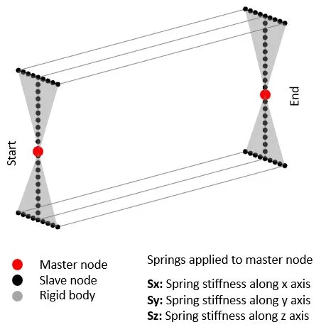
Les ressorts nodaux peuvent être attachés aux nœuds maîtres aux extrémités d'un membre. Chaque extrémité permet trois directions de rigidité de ressort le long du x, Y, Il est recommandé de revérifier les matériaux et les sections utilisés dans votre projet afin que le poids propre de votre structure soit aussi précis que possible. Si une rotation de rotation est requise, Des ressorts ponctuels supplémentaires peuvent être appliqués aux extrémités avec un décalage du nœud maître (Reportez-vous au «nœud linéaire printemps’ Section pour plus de détails).

Zone de plaque
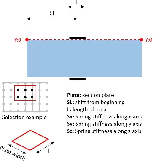
Les ressorts sont appliqués à la partie plaque. Ici, vous sélectionnez la plaque, position du centre d'une zone du côté gauche (SL), longueur (L), et largeur (B) de la zone, et raideur directionnelle du ressort. Les ressorts seront distribués entre les nœuds à l'intérieur de la zone. Les ressorts nodaux peuvent être prévisualisés en cliquant sur le bouton Aperçu.
Node Spring linéaire
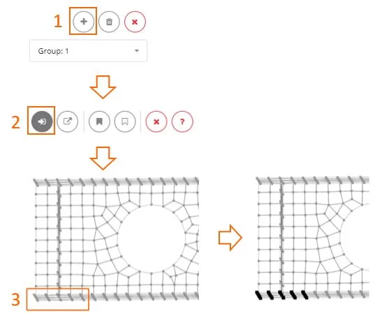
Commencez par créer un nouveau groupe en utilisant le '+’ bouton. ensuite, Sélectionnez les nœuds à l'aide de la méthode de sélection du cadre ou du polygone et définissez la rigidité directionnelle pour eux. Si vous avez besoin d'une rigidité différente pour les nœuds, Créer un autre groupe. La sélection ou la désélection peut être réalisée à l'aide des outils Cadre ou Polygone..

Node de compression uniquement
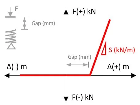
Pour chaque nœud, Vous pouvez définir une rigidité à ressort qui fonctionne dans une seule direction. Par exemple, Cela peut simuler le contact entre la surface du corps et le sol en permettant une raideur de compression et une séparation libre dans la direction opposée. Aussi, Vous pouvez spécifier un écart qui doit être fermé avant le contact. En ajustant la rotation autour des axes y et z, Vous pouvez contrôler l'orientation de la rigidité de la compression du ressort.

Commencez par créer un nouveau groupe en utilisant le '+’ bouton. ensuite, Sélectionnez les nœuds à l'aide de la méthode de sélection du cadre ou du polygone et définissez la rigidité directionnelle pour eux. Si vous avez besoin d'une rigidité différente pour les nœuds, Créer un autre groupe. La sélection ou la désélection peut être réalisée à l'aide des outils Cadre ou Polygone..


