Resumen
EN 1993-1-1: Diseño de Estructuras de Acero (Eurocódigo 3) Describe pautas de diseño para miembros estructurales de acero para uso en edificios usando el método del estado límite.. El diseño en estado límite implica comparar cargas de diseño factorizadas con capacidades reducidas de secciones y miembros.. Estos factores están destinados a tener en cuenta la variabilidad en las condiciones de carga y las propiedades del material.. Para el estado límite último (ULS) diseñar para estar satisfecho, la siguiente relación debe ser cierta:
\(ULS \;Factor * Carga ≤ Reducción \;Factor * Capacidad)
Esta guía de diseño describe el procedimiento para diseñar un miembro de acero estructural de acuerdo con EN 1993-1-1 utilizando la EN 1993-1-1 Diseño de miembros de acero módulo.
Mira nuestro Eurocódigo 3 Demostración de diseño de acero
Contenido
Propiedades materiales
Fabricación
EN 1993-1-1 proporciona orientación de diseño para cuatro tipos de fabricación de acero estructural:
- Secciones Laminadas en Caliente: Las secciones laminadas en caliente se fabrican calentando y laminando palanquillas de acero a través de un molino para lograr la forma requerida.. Los ejemplos incluyen secciones I UB/UC/UBP, Secciones en T, Canales y secciones angulares.
- Secciones soldadas: soldado (o fabricado) Las secciones se componen de varias placas planas laminadas en caliente soldadas entre sí longitudinalmente para formar una forma de acero.. Las secciones fabricadas a medida suelen estar soldadas.
- Secciones terminadas en caliente: Las secciones acabadas en caliente se producen calentando el acero más allá de su temperatura de recristalización antes del laminado para mejorar la resistencia del producto final.. Estos perfiles son casi siempre perfiles huecos estructurales. (RHS/SHS/CHS).
- Secciones conformadas en frío: Las secciones conformadas en frío se fabrican presionando palanquillas de acero a través de un molino a temperatura ambiente.. El conformado en frío se puede utilizar para producir secciones huecas estructurales y secciones abiertas más delgadas.. Nota ES 1993-1-1 solo proporciona orientación para secciones huecas conformadas en frío.
Grado de acero
Europa y el Reino Unido tienen numerosos grados de acero. (fortalezas) que se puede utilizar para el diseño según EN 1993-1-1. Existen varias normas europeas de materiales para diferentes tipos de fabricación de acero.:
- EN 10025: Productos laminados en caliente.
- EN 100210: Perfiles huecos estructurales acabados en caliente.
- EN 10219: Secciones huecas estructurales soldadas conformadas en frío.
Secciones Laminadas en Caliente (EN 10025)
A continuación se describen las disponibilidades de grados comunes y los límites elásticos indicativos para las formas de acero laminado en caliente.:
Límite elástico mínimo (MPa) |
|||||||||
|---|---|---|---|---|---|---|---|---|---|
| Calificación | ≤16mm | 16-40mm | 40-63mm | 63-80mm | 80-100mm | 100-150mm | 150-200mm | 200-250mm | 250-400mm |
| S 235 | 235 | 225 | 215 | 215 | 215 | 195 | 185 | 175 | 165 |
| S 275 | 275 | 265 | 255 | 245 | 235 | 225 | 215 | 205 | 195 |
| S 355 | 355 | 345 | 335 | 325 | 315 | 295 | 285 | 275 | 265 |
| S 460 | 460 | 440 | 420 | 400 | 390 | 390 | – | – | – |
Resistencia mínima a la tracción (MPa) |
||||||
|---|---|---|---|---|---|---|
| Calificación | ≤3mm | 3-100mm | 100-150mm | 150-250mm | 250-400mm | |
| S 235 | 360 | 350 | 350 | 340 | 330 | |
| S 275 | 430 | 410 | 400 | 380 | 380 | |
| S 355 | 510 | 470 | 450 | 450 | 450 | |
| S 460 | – | 550 | 530 | – | – | |
Secciones huecas estructurales acabadas en caliente (EN 100210)
A continuación se describen las disponibilidades de calidades comunes y los límites elásticos indicativos para secciones huecas estructurales acabadas en caliente.:
Límite elástico mínimo (MPa) |
||||||
|---|---|---|---|---|---|---|
| Calificación | ≤16mm | 16-40mm | 40-63mm | 63-80mm | 80-100mm | 100-120mm |
| S 235 H | 235 | 225 | 215 | 215 | 215 | 195 |
| S 275 H | 275 | 265 | 255 | 245 | 235 | 225 |
| S 355 H | 355 | 345 | 335 | 325 | 315 | 295 |
Resistencia mínima a la tracción (MPa) |
|||
|---|---|---|---|
| Calificación | ≤3mm | 3-100mm | 100-120mm |
| S 235 H | 360 | 360 | 350 |
| S 275 H | 430 | 410 | 400 |
| S 355 H | 510 | 470 | 450 |
Producir & Fuerza de Tensión
El límite elástico de un material es el límite de tensión más allá del cual se producirá la deformación plástica.. La resistencia a la tracción es la tensión máxima que puede soportar un material antes de fallar. / se rompe. El límite elástico y la resistencia a la tracción de las secciones de acero dependen del grado y el espesor del acero.. Normalmente, la resistencia aumenta con la calidad del acero, pero disminuye con el aumento del espesor del acero..
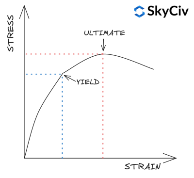
EN 1993-1-1 Tabla 3.1 proporciona un enfoque simplificado para calcular el límite elástico y la resistencia a la tracción de una sección en función de su calidad y espesor.. Se puede realizar un cálculo más detallado de la resistencia del material consultando la norma de material relevante.. The SkyCiv ES 1993-1-1 El módulo Diseño de miembros de acero no no Utilice esta simplificación y, en su lugar, consulte las normas de materiales pertinentes para el cálculo de la resistencia del material..
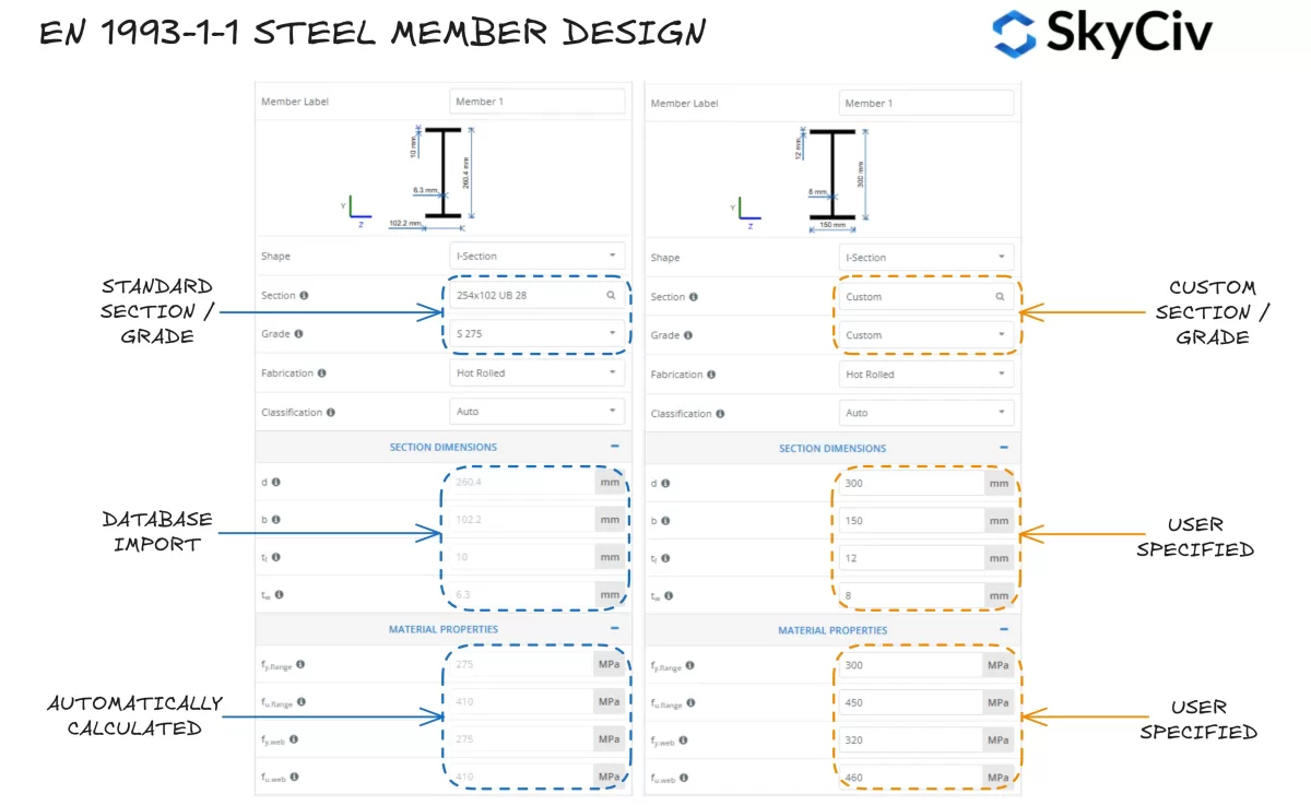
Seleccionar una sección en SkyCiv ES 1993-1-1 Diseño de miembros de acero
El SkyCiv EN 1993-1-1 Diseño de miembros de acero La herramienta permite a los usuarios seleccionar una sección de acero estándar de la base de datos SkyCiv o diseñar una sección completamente personalizada.. El programa calcula automáticamente los valores del límite elástico para el ala de la sección y el alma en función del grado de acero seleccionado.. Los usuarios también pueden adoptar un grado de acero personalizado e ingresar manualmente las propiedades del material si es necesario..
Clasificación de secciones
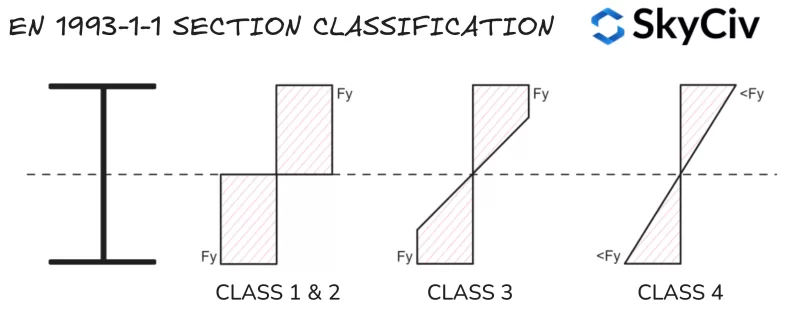
La clasificación de secciones es un sistema utilizado por EN 1993-1-1 Identificar la susceptibilidad de una sección al pandeo local antes de alcanzar su capacidad plástica total.. Las formas grandes y esbeltas suelen ser más susceptibles al pandeo local que las pequeñas., formas rechonchas. El SkyCiv EN 1993-1-1 Diseño de miembros de acero La herramienta calcula automáticamente la clasificación de secciones de acero estándar y personalizadas en función de las condiciones de carga aplicadas.. Eurocódigo 3 tiene cuatro categorías de clasificación de secciones:
- Clase 1: Secciones que pueden formar una bisagra plástica y desarrollar su momento plástico/resistencia axial., lo que significa que toda la sección puede alcanzar su límite elástico bajo flexión y/o compresión.. Clase 1 Las secciones también tienen una alta capacidad de rotación.. Las propiedades de la sección plástica se utilizan en los cálculos de capacidad..
- Clase 2: Secciones con la capacidad de formar una bisagra de plástico pero con capacidad de rotación limitada.. Eurocódigo 3 trata clase 1 y clase 2 secciones de manera similar para casi todos los cálculos de capacidad.
- Clase 3: Secciones que pueden alcanzar el límite elástico en su fibra de extrema compresión., pero se pandean localmente antes de que se logre la resistencia al momento plástico.. Las propiedades de la sección elástica se utilizan en los cálculos de capacidad..
- Clase 4: El pandeo local ocurrirá antes de que se alcance el límite elástico en parte/s de la sección.. Las propiedades de sección elástica reducida se utilizan en los cálculos de capacidad..
Nota, Clase 4 las secciones incluyen complejidad adicional en el cálculo de las propiedades de la sección / resistencia y no están cubiertos en esta guía.
Elementos de compresión
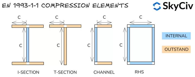
La clasificación de las secciones se determina dividiendo una sección en una serie de elementos a compresión y calculando su esbeltez. (longitud clara en relación con el espesor). Los elementos se clasifican en:
- Interno: Restringido contra pandeo en ambos extremos – Es decir. red de una sección I.
- Destacar: Sólo protegido contra pandeo en un extremo – Es decir. brida de una sección en I.
Los valores de esbeltez calculados se comparan con la Tabla 5.2 en ES 1993-1-1 para determinar su clase. La clasificación de la sección se toma como la clasificación menos favorable de sus elementos a compresión.. Nota, La clasificación de la sección cambia dependiendo de las fuerzas sobre la sección. (fuerza axial particularmente variable). Los métodos para clasificar cada tipo de carga se resumen a continuación..
Ratios de clasificación
Piezas sujetas a compresión
Los elementos en compresión pura se clasifican en función de su esbeltez únicamente utilizando los límites que se detallan a continuación..
| Clase | Partes internas | Piezas destacadas | |
| 1 | c / t ≤ 33ε | c / t ≤ 9ε | |
| 2 | c / t ≤ 38e | c / t ≤ 10ε | |
| 3 | c / t ≤ 42ε | c / t ≤ 14e | |
Dónde:
\(ε = sqrt{\frac{235}{f_y}}\)
Piezas sujetas a flexión
Los elementos internos en flexión pura se clasifican en función de su esbeltez dentro de los límites que se detallan a continuación..
| Clase | Partes internas | |
| 1 | c / t ≤ 72ε | |
| 2 | c / t ≤ 83e | |
| 3 | c / t ≤ 124e | |
Los elementos sobresalientes sujetos a flexión pura se clasifican según la relación entre la tensión de compresión y la tensión de tracción bajo el valor del momento de flexión, lo que da como resultado una tensión de compresión igual al límite elástico en el extremo de la fibra.. El método para calcular este ratio se detalla en la siguiente sección..
Piezas sujetas a compresión & Doblar
Los elementos sujetos a compresión y flexión combinadas se clasifican en función de su capacidad de compresión. / Distribución de la tensión de tracción bajo la carga de compresión aplicada.. Esta relación está representada por el símbolo α para la distribución de tensiones plásticas y el símbolo ψ para la distribución de tensiones elásticas..
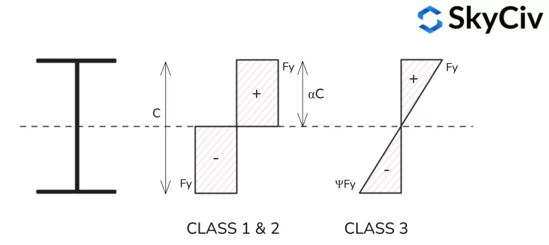
Distribución de tensiones plásticas
Fórmulas para calcular la relación de tensión plástica. (una) Para perfiles de diferentes formas se proporcionan a continuación..
Distribución de tensión plástica en sección I

Distribución de tensión plástica en sección en T
Tenga en cuenta que las distribuciones de tensión del eje menor para las secciones en T son similares a las de una sección en I..

Distribución de tensión de la sección plástica del canal
Tenga en cuenta que las distribuciones de tensión del eje principal para las secciones en T son similares a las de una sección en I..

Distribución de tensiones plásticas RHS

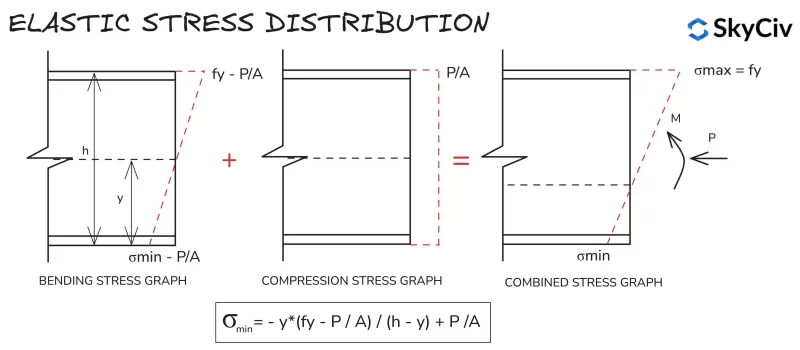
Distribución de tensión elástica
Los cálculos de distribución de tensiones elásticas son similares para todas las secciones y formas., debido a la distribución lineal de tensiones entre las fibras extremas. A continuación se muestra la fórmula para calcular la tensión mínima en una sección sometida a compresión y flexión aplicada..
Clasificación de secciones en SkyCiv ES 1993-1-1 Diseño de miembros de acero
El SkyCiv UNO 1993-1-1 Diseño de miembros de acero La herramienta determina automáticamente la clasificación de secciones estándar y personalizadas según la carga de entrada del usuario.. Un ejemplo de salida para un Grado S 275, 430A continuación se detalla el canal x100x64 con 20 kN de carga de compresión..
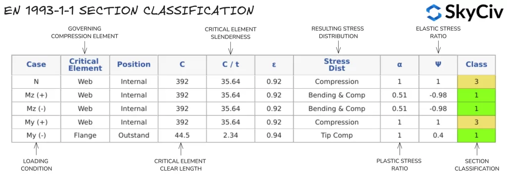
Se utiliza un único valor de clasificación de sección para todos los cálculos basados en la fuerza axial aplicada y la dirección del momento flector aplicado.. Si a un miembro se le aplica un momento flector alrededor de ambos ejes, Se adopta la clasificación más conservadora de cada dirección.. Los usuarios también pueden anular el cálculo automático de la clasificación de secciones y especificar una clasificación manualmente.
Nota, Cláusula 5.4.1(3) especifica que las secciones simplemente simétricas (como secciones en T y canales) no se pueden diseñar mediante análisis plástico cuando se doblan sobre su eje no simétrico. Por lo tanto, a las secciones de esta naturaleza se les asigna automáticamente Clase 3.
Resistencia de sección
Doblar
Resistencia a la flexión de la sección
La capacidad del momento de flexión de la sección se calcula utilizando EN 1993-1-1 Cláusula 6.2.5.
\(METRO_{c,Rd} = W*f_y/γ_{M0}\)
Donde W es el módulo de sección plástica. (Wpl) para clase 1 & 2 secciones, o el módulo de sección elástica (Wel) para clase 3 secciones, Fy es el límite elástico del material y γ es el factor de reducción de seguridad parcial.
El módulo de sección de una forma es una propiedad geométrica que cuantifica la resistencia a la flexión de una forma.. El módulo de la sección plástica supone que toda la sección alcanza su límite elástico bajo flexión.. El módulo de sección plástica de una sección se calcula de la siguiente manera:
\(W_{pl} = A_{C} * y_{C} + UNA_{T} * y_{T} \)
Donde unC y unT son las áreas a cada lado del eje neutro plástico (ANP), y yc / yt son la distancia desde el PNA al centroide de esas áreas. Nota, la ubicación del PNA es igual a la ubicación del centroide geométrico para formas simétricas, pero no igual a la ubicación del centroide geométrico para formas asimétricas.
El módulo de sección elástica asume toda la sección. (forma) permanece elástico al doblarse, Es decir. ninguna parte de la sección excede el límite elástico (Fy) del material. El módulo de sección elástica de una sección se calcula de la siguiente manera:
\(W_{el} = frac{I}{y}\)
Donde I es el segundo momento del área e y es el centroide geométrico de la forma.. Nota para una forma asimétrica, El valor del módulo elástico utilizado en el diseño es el valor menor para la flexión positiva y negativa alrededor de ese eje..
Calcular la resistencia a la flexión de una sección en SkyCiv ES 1993-1-1 Diseño de miembros de acero
Una vez calculada la Clasificación de Sección correspondiente, El módulo calcula la capacidad de momento flector de la sección. (Mc) sobre cada eje principal. Los resultados para el mismo canal 430x100x64 se muestran en el siguiente ejemplo.

Corte
Resistencia al corte de la sección
La resistencia al corte se calcula utilizando EN 1993-1-1 Cláusula 6.2.6. Los cálculos de capacidad dependen de la clasificación de la sección del miembro de acero.. Capacidad para Clase 1 & 2 Las secciones se calculan en base a la resistencia al corte plástico., mientras que para la Clase se utiliza una resistencia al corte elástica 3 & 4 secciones.
La resistencia al corte del plástico se calcula utilizando la siguiente fórmula:
\(V_{pl,Rd}=A_v * (f_y / \sqrt{3}) / do_{M0}\)
Donde Av es el área de corte de la sección en la dirección de la fuerza cortante aplicada. Para la mayoría de las secciones, esta área es equivalente al área del alma para el corte en la dirección del eje mayor., y el área de las bridas para la otra dirección. Las fórmulas para calcular el área de corte se proporcionan en EN. 1993-1-1 Cláusula 6.2.6(3).
La resistencia al corte elástico se calcula utilizando la siguiente relación, lo que garantiza que el esfuerzo cortante en el punto crítico de la sección transversal sea menor que el límite elástico.
\(t_{Ed}/(f_y / (\sqrt{3 * do_{M0}})) ≤ 1\)
El esfuerzo cortante en este punto crítico se calcula de la siguiente manera:
\(t_{Ed}=(V_{Ed} * S)/(I * t)\)
donde vEd es la fuerza cortante aplicada, S es el primer momento del área., I es el momento de sección del área y t es el espesor en el lugar de tensión crítica.
Luego, la fórmula del esfuerzo cortante elástico se puede organizar para representar un valor de resistencia. (en kN):
\(V_{el,Rd} = (I * t * \sqrt{3})/(S * f_y)\)
Pandeo por cortante
Largo, Las almas delgadas pueden pandearse bajo la fuerza de corte aplicada antes de que alcancen su resistencia elástica al corte.. Las almas son susceptibles a pandeo por cortante si satisfacen la siguiente fórmula de EN 1993-1-1 Cláusula 6.2.6(6):
\(h / t > 72 * y/n \)
Dónde η es un factor generalmente tomado como 1.0. Las redes susceptibles a pandeo por cortante deben comprobarse de acuerdo con la Sección 5 o y 1993-1-5. Nota, capacidad de corte según EN 1993-1-5 no está cubierto en SkyCiv ES 1993-1-1 herramienta, pero se mostrará una advertencia si una sección es susceptible a pandeo por cortante.
Impacto de la fuerza cortante en la flexión & Resistencia a la compresión
Una fuerza cortante elevada aplicada puede tener un impacto negativo en el momento y la resistencia axial de una sección.. En ES 1993-1-1, Este impacto se captura reduciendo el límite elástico de la sección en relación con la magnitud del corte aplicado. (referir cláusula 6.2.8 & 6.2.10). Cuando la fuerza cortante de la sección es con menos de la mitad de su resistencia al corte plástico en esa dirección, este impacto puede ser ignorado. Si el corte aplicado es mayor que este valor, el límite elástico reducido se calcula de la siguiente manera:
\(F_{y,Rd} = (1 -ρ) * f_y \)
Dónde:
\(ρ = (2 * V_{Ed} / V_{pl,Rd} – 1)^2)
El SkyCiv UNO 1993-1-1 Diseño de miembros de acero El módulo calcula automáticamente cualquier reducción en el límite elástico debido a una alta fuerza de corte aplicada y utiliza este valor reducido en los cálculos de resistencia a flexión y compresión de la sección.. Nota, Esta reducción sólo se aplica para la resistencia de la sección de un miembro., no la resistencia al pandeo.
Calcular la resistencia al corte en SkyCiv ES 1993-1-1 Diseño de miembros de acero
El SkyCiv UNO 1993-1-1 Diseño de miembros de acero La herramienta calcula la capacidad de corte de una sección en ambas direcciones del eje principal.. Resultados de los cálculos de resistencia al corte para un 254×102 UB 28 se detallan a continuación.

Compresión
Resistencia a la compresión de la sección
EN 1993-1-1 Cláusula 6.2.4 calcula la capacidad de compresión (nortec) de una clase cargada concéntricamente 1,2 o 3 sección de la siguiente manera:
\(NORTE_{c,Rd} = A*f_y / do_{M0}\)
Donde A es el área bruta de la sección transversal y fy es el límite elástico de la sección.
Calcular la resistencia a la compresión de la sección en SkyCiv ES 1993-1-1 Diseño de miembros de acero
El SkyCiv uno 1993-1-1 Diseño de miembros de acero La herramienta calcula la resistencia a la compresión de la sección. (nortec,Rd) para secciones europeas estándar y secciones personalizadas definidas por el usuario. Resultados de los cálculos de resistencia a la compresión de la sección para un 254×102 UB 28 se detallan a continuación.

Tensión
Resistencia a la tensión de la sección
EN 1993-1-1 Cláusula 6.2.3 calcula la capacidad de un miembro de tensión (Nuevo Testamento) ser la menor entre la resistencia a la tensión plástica y la resistencia a la tensión última:
\(NORTE_{t,Rd} = mín.(A*f_{y}/do_{M0} \; ,\; 0.9*UNA_{norte}*f_u /γ_{M2})\)
Donde A es el área bruta de la sección., Anorte es el área neta de la sección transversal (área bruta excluyendo penetraciones/agujeros), Fy es el límite elástico de la sección, Ftu es el de tensión (último) fuerza de la sección.
Calcular la resistencia a la tensión en SkyCiv ES 1993-1-1 Diseño de miembros de acero
El SkyCiv UNO 1993-1-1 Diseño de miembros de acero El módulo asume que no hay agujeros significativos presentes en la sección., por lo tanto Anorte se toma como igual a A. Resultados de los cálculos de resistencia a la tensión de la sección para un 254×102 UB 28 se detallan a continuación.

Doblar & Fuerza Axial
Cuando a una sección se le ha aplicado tensión axial o fuerza de compresión., Se debe tener en cuenta el efecto de esta fuerza sobre la resistencia al momento flector de la sección.. El método para evaluar este efecto descrito en EN 1993-1-1 Cláusula 6.2.9 varía según la clase 1 & 2 y clase 3 secciones.
Clase 1 & 2 compuestas
La fuerza axial y de flexión combinada se evalúa para secciones de plástico reduciendo la resistencia al momento plástico en cada dirección en una cantidad proporcional a la fuerza axial.. Esta resistencia al momento reducido se denomina con el símbolo M.norte,Rd. Cálculo de Mnorte,Rd varía según la forma de la sección y se describe en EN 1993-1-1 Cláusula 6.2.9.1. Una vez que se calcula la resistencia al momento reducido, El siguiente criterio se utiliza para evaluar la resistencia axial y de flexión combinada.:
\( (METRO_{y,Ed} / METRO_{El,Rd})^a + (METRO_{z,Ed} / METRO_{Nueva Zelanda,Rd})^ segundo ≤ 1\)
Dónde α y β son constantes que varían con la forma de la sección. – Consulte ES 1993-1-1 Cláusula 6.2.9.1.
Clase 3 compuestas
En cambio, la fuerza axial y de flexión combinada en secciones elásticas se evalúa utilizando una fórmula de tensión elástica general que se detalla a continuación.:
\( NORTE_{Ed} / NORTE_{c,Rd} + METRO_{z,Ed} / METRO_{cz,Rd} + METRO_{y,Ed} / METRO_{cy,Rd} ≤ 1\)
Tenga en cuenta que cualquier reducción en el límite elástico requerida debido a la fuerza cortante aplicada debe usarse en el cálculo de los valores de resistencia de la sección en las fórmulas anteriores..
Resistencia al pandeo
Doblar
Resistencia al pandeo lateral
Largo, Los miembros de acero no restringidos pueden fallar en pandeo lateral antes de alcanzar su resistencia al momento de flexión de la sección.. El pandeo lateral por torsión ocurre cuando la sección gira alejándose de su eje mayor hacia su eje menor., lo que significa que se reduce la resistencia al momento en la dirección de la flexión aplicada. En EN se proporciona orientación para calcular la resistencia al pandeo lateral de los miembros. 1993-1-1 Cláusula 6.3.2.
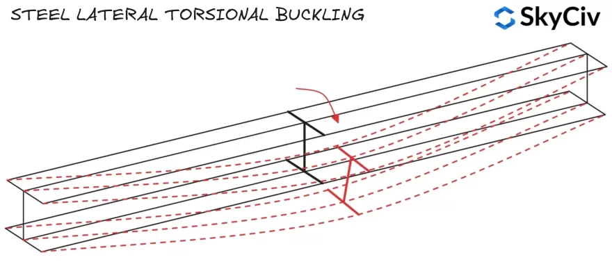
La resistencia al pandeo lateral se calcula utilizando la siguiente fórmula:
\(METRO_{b,Rd} =x_{LT}*W*f_y/ γ_{M1}\)
Donde W es el módulo de sección plástica. (Wpl) para clase 1 & 2 secciones, o módulo de sección elástica (Wel) para clase 3 secciones. hLT es un factor de reducción para el pandeo lateral-torsional, En EN se proporciona orientación para calcular este factor. 1993-1-1 Cláusula 6.3.2.2 y 6.3.2.3.
Brida de compresión
Los miembros fallan en pandeo lateral-torsional cuando el ala comprimida gira y se desplaza lateralmente. Si el ala comprimida de un miembro está suficientemente restringida, No será susceptible al pandeo lateral por torsión. (Consulte ES 1993-1-1 Cláusula 6.3.2.1(2)). A continuación se muestran las ubicaciones de las bridas de compresión para secciones estándar bajo carga vertical..
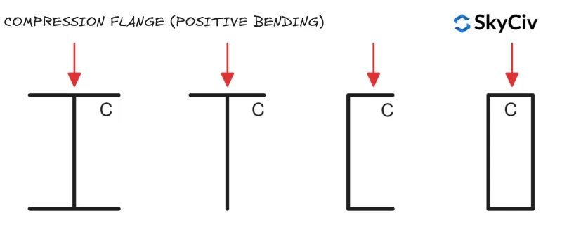
Secciones huecas circulares (CHS) y secciones huecas cuadradas (SHS) No son susceptibles al pandeo lateral por torsión., ya que tienen igual resistencia de momento de sección alrededor de ambos ejes (lo que significa que el desplazamiento lateral y la rotación no afectan la resistencia a la flexión del miembro).
Factor de reducción de pandeo de torsión lateral
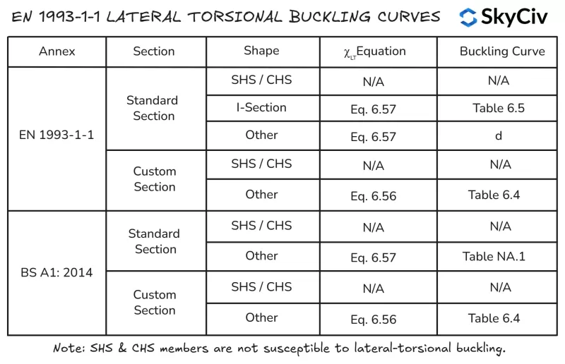
hLT se calcula en EN 1993-1-1 Usando cualquier sección 6.3.2.2 (Caso general) o sección 6.3.2.3 (Secciones enrolladas o secciones soldadas equivalentes). Sección de 6.3.2.3 es aplicable para todos “para el” secciones y formas (incluyendo secciones huecas) y sus equivalentes soldados. Sección de 6.3.2.2 es aplicable a cualquier sección que no entre en la categoría anterior, incluyendo secciones personalizadas y construidas.
Sección de 6.3.2.2 Utiliza la ecuación 6.56 Para el cálculo del hecho de reducción de pandeo torsional lateral.LT Mientras que la sección 6.3.2.3 Utiliza la ecuación 6.57. El SkyCiv UNO 1993-1-1 Diseño de miembros de acero El módulo sigue la lógica que se describe a continuación para la aplicación de la ecuación 6.56 y 6.57.
Resistencia al pandeo por flexión del eje menor
La capacidad de flexión de un miembro doblado alrededor de su eje menor es igual a la resistencia de la sección del eje menor alrededor de ese eje.. La capacidad de la sección del eje menor es la capacidad mínima que una sección puede alcanzar alrededor de cualquier eje., por lo tanto, el miembro no puede girar desde este eje hacia una orientación menos favorable..
Cálculo de la resistencia a la flexión de miembros en EN 1993-1-1 Diseño de miembros de acero
El SkyCiv UNO 1993-1-1 Diseño de miembros de acero La herramienta calcula Realiza cálculos de resistencia a la torsión lateral según EN. 1993-1-1 Cláusula 6.3.2.2 y cláusula 6.3.2.3, dependiendo de la forma de la sección y del Anexo Nacional aplicado. Los usuarios también tienen la opción de especificar que un miembro tenga “Restricción de torsión continua” que omitirá automáticamente todas las comprobaciones de pandeo lateral-torsión. Cálculos de resistencia al pandeo lateral para un 254 de 5000 mm de largo×102 UB 28 se detallan a continuación.

Compresión
Resistencia al pandeo por flexión
La resistencia al pandeo por compresión de un miembro también se ve afectada por su longitud y rigidez lateral.. Desenfrenado, Es probable que los miembros más largos fallen debido al pandeo por flexión antes de que la sección (calabaza) se alcanza la capacidad. EN 1993-1-1 Cláusula 6.3.1.3 proporciona orientación sobre el cálculo de la resistencia al pandeo por flexión del miembro para la Clase 1, 2 & 3 secciones cruzadas:
\(NORTE_{b,Rd} = x*A*f_y/ γ_{M1}\)
Dónde χ es un factor de reducción para el pandeo por flexión. En EN se proporciona orientación para calcular este factor. 1993-1-1 Cláusula 6.3.1.3. FLa capacidad de flexión debe verificarse en ambos ejes para encontrar el valor gobernante para el miembro..
Cálculo de la resistencia al pandeo por flexión en EN 1993-1-1 Diseño de miembros de acero
El SkyCiv UNO 1993-1-1 Diseño de miembros de acero La herramienta calcula la resistencia al pandeo por flexión en ambos ejes principales basándose en las longitudes de restricción y los factores de longitud efectiva especificados por el usuario.. Resistencia al pandeo por flexión de un 254×102 UB 28 con una longitud libre de 6000 mm y 5000 mm en los ejes Z e Y (respectivamente) se detallan a continuación.

Resistencia al pandeo por torsión-flexión
Las secciones transversales abiertas también son susceptibles al pandeo por torsión-flexión., que puede ser menor que la resistencia del miembro al pandeo por flexión. Secciones huecas circulares (CHS) y secciones huecas cuadradas (SHS) Los miembros no son susceptibles al pandeo por torsión-flexión.. EN 1993-1-1 Cláusula 6.3.1.4 proporciona orientación sobre el cálculo de la resistencia al pandeo por torsión-flexión del miembro:
\(NORTE_{BT,Rd} = χ_T*A*f_y/ γ_{M1}\)
Dónde hLT es un factor de reducción para el pandeo por torsión-flexión. En EN se proporciona orientación para calcular este factor. 1993-1-1 Cláusula 6.3.1.3. FLa capacidad de flexión debe verificarse en ambos ejes para encontrar el valor gobernante para el miembro..
Cálculo de la resistencia al pandeo por torsión-flexión en EN 1993-1-1 Diseño de miembros de acero
El SkyCiv UNO 1993-1-1 Herramienta de diseño de miembros de acero calcula la resistencia al pandeo por torsión-flexión para secciones abiertas y cerradas aplicables de acuerdo con EN 1993-1-1 Cláusula 6.3.1.4 basado en la longitud de restricción de compresión en el eje principal según lo especificado por el usuario. Resistencia al pandeo por torsión-flexión de un 254×102 UB 28 con una longitud libre de 6000 mm se detallan a continuación.

Software SkyCiv de Diseño Estructural
SkyCiv ofrece una amplia gama de software de análisis estructural y diseño de ingeniería, incluidos:
-
- Eurocódigo 3 para Diseño en Acero
- Eurocódigo 9 Diseño de aluminio
- Eurocódigo 3 Diseño de correas
- Eurocódigo 3 Calculadora de grupo de pernos
- Eurocódigo 3 Calculadora de grupo de soldadura
- Eurocódigo 2 Calculadora de longitud de desarrollo
- Eurocódigo 2 Calculadora de longitud de vuelta
- Eurocódigo 5 Calculadora de diseño de madera
- Eurocódigo 3 Calculadora de diseño de andamios
Desarrollador de software | Ingeniero estructural
BEng (Civil), DipEng (Software)


