
Si lees nuestro artículo anterior, AISC 360: Diseño de conexión de corte, tendría una buena idea de cómo se diseñan las conexiones simples bajo AISC 360. Una conexión a cortante sólo tiene que producir la reacción del extremo de la viga.. Una conexión momentánea tiene que generar esa reacción y el momento final con ella., lo que trae la columna de soporte al problema. En este artículo, analizamos un ejemplo de conexión de momento entre dos miembros en forma de I y repasamos los criterios de diseño que deben cumplirse.. También podemos llegar a los mismos resultados directamente a través del SkyCiv Connection Design módulo, que comprueba estas conexiones a AISC 360-16 en TEA o LRFD.
Como en el ejemplo de conexión de corte., Los cálculos aquí utilizan el diseño de tensión permitida. (ASD) método. Si no está familiarizado con la diferencia entre ASD y LRFD en el diseño estructural, asegurate que mira nuestro video explicando esto.
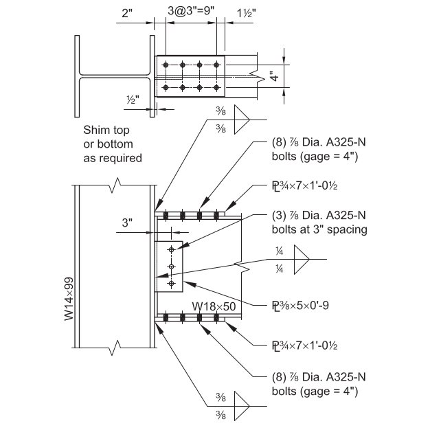
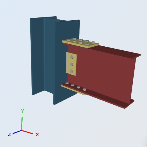
En este ejemplo, Evaluamos la capacidad de un atornillado. Rebordeado Totalmente restringido (FR) Conexión de momento entre una viga W18x50 y una columna W14x99, usando las dimensiones, soldaduras y cargas que se muestran a continuación. La conexión tiene que soportar la reacción vertical del extremo de la viga y el momento extremo desarrollado.. Comparado con una conexión cortante, la diferencia es el par de placas que transportan las fuerzas del ala de la viga sobre el ala de la columna de soporte.
Las placas de ala convierten el momento final de la viga en un par de tensión y compresión.. La placa superior tira, la placa inferior empuja, y ambas fuerzas aterrizan en el ala de la columna como fuerzas concentradas. Es por eso que una conexión de momento necesita que la columna verifique localmente que una conexión de corte no.
Dado:
Cargas de nivel de servicio & Material:
Corte vertical por carga muerta (enfermedad venérea) = 7.0 kips
Corte vertical por carga viva (VL) = 21.0 kips
Momento de la carga muerta (Maryland) = 42.0 kip-ft
Momento de carga viva (ML) = 126.0 kip-ft
Material de la placa: ASTM A36, Fy = 36 KSI, Fu = 58 KSI
Material de vigas y columnas: ASTM A992, Fy = 50 KSI, Fu = 65 KSI
Geometría de vigas y columnas:
Calculadora de: W18x50; bf = 7.50 in, tf = 0.570 in, d = 18.0 in, tw = 0.355 in, Sx = 88.9 en ^ 3
Columna: W14x99; bf = 14.6 in, tf = 0.780 in, d = 14.2 in, tw = 0.485 in, kdes = 1.38 in
Placa de brida: 3/4 en grueso; 7.0 en x 12.5 en dimensiones
Placa Web: 3/8 en grueso; 5.0 en x 9.0 en dimensiones
Accesorios (Pernos y soldaduras):
Brida: (8) – 7/8-in.-diámetro Pernos ASTM F3125 Grado A325-N en orificios estándar
Placa Web: (3) – 7/8-in.-diámetro Pernos ASTM F3125 Grado A325-N en orificios estándar
70-filetes de electrodo ksi. A325 y A490 son grados dentro de ASTM F3125, que consolidó las especificaciones de pernos independientes más antiguas.
Cálculos de carga:
LRFD Cargas (Solo referencia):
Reacción vertical definitiva (Rtu) = 1.2 (7.0 kips ) + 1.6 (21.0 kips ) = 42.0 kips
Último momento (Mtu) = 1.2 (42.0 kip-ft) + 1.6 (126.0 kip-ft) = 252.0 kip-ft
ASD Cargas:
Reacción vertical permitida (Ra) = 7.0 kips + 21 kips = 28.0 kips
Momento permitido (Ma) = 42.0 kip-ft + 126 kip-ft = 168.0 kip-ft
Todo lo siguiente se compara con las cargas del ASD.. Mantenga los dos métodos separados: ASD compara las cargas de servicio con la fuerza permitida, LRFD compara las cargas factorizadas con la resistencia de diseño, y las cifras de LRFD anteriores se llevan solo para que pueda comparar los dos.
Solución basada en el software de diseño de conexiones SkyCiv:
ERRATA: El ancho de la placa de la brida en este ejemplo fue 7.0 in pero el ancho utilizado en los cálculos es 7.50 in, de ahí la diferencia de valores.
Fuerza de brida
Cada cheque que sigue está impulsado por un número., la fuerza en la placa de brida. El momento final se resuelve en un par que actúa en los centroides de las placas., entonces el brazo de palanca es la profundidad de la viga más el espesor de una placa:
PAGde = [ 168.0 kip-ft (12 pulg / pie) ] / (18.0 in + 0.75 in) = 107.5 kips
Placa de brida a brida W14x99, Fuerza de soldadura
Resistencia de las soldaduras de filete, Ω = 2.0
Tamaño de soldadura, t = 0.375 in
Fnoroeste = 0.6 FEXX [ 1.0 + 0.5 sin1.5 (θ) ]
Dónde, θ = el ángulo que forma la carga con el eje de soldadura
= 90, para soldaduras cargadas transversalmente
= 0, para soldaduras cargadas longitudinalmente
Resistencia por unidad de tamaño de soldadura:
Tensión de soldadura admisible, Faw = 0.6 (70KSI) / 2.0 = 21 KSI
longitud transversal, lt = 7 in
longitud longitudinal, ll = 0 in
longitud efectiva total, l = lt (1.5) + ll (1.0) = 10.5 in
El 1.5 en la longitud transversal está el aumento de fuerza direccional, 1.0 + 0.5 sin1.5(90).
(Ra / a) = 21 KSI (10.5 in) = 220.5 kips / in
Tamaño efectivo (garganta) de soldadura de filete, a:
0.707 = el coseno o seno de 45 grados
a = (0.707) t = 0.265 in
dos soldaduras, uno a cada lado del plato:
Ra = (Ra / a) a (2) = 220.50 (0.265 in) 2 = 116.9 kips
Relación de capacidad de diseño, DCR:
carga requerida, R = 107.5 kips
capacidad total, Ra = 116.9 kips
DCR = (107.5 / 116.9) = 0.919, OK
Cheques locales de columna
Estas cuatro comprobaciones preguntan si el W14x99 puede aceptar la fuerza del ala sin rigidez local.. Todos ellos se comparan con la misma fuerza de brida.:
Fuerza de brida, PAGde = 107.5 kips
- Rendimiento local web, Ω = 1.5
Rnorte / Ω = [ Fes tw (5k + lb) ] / Ω = 50ksi (0.485in) [ 5(1.38in) + 0.75in ] / 1.5 = 123.7 kips
aquí tw es el espesor del alma de la columna y lb la longitud del rodamiento, tomado como el espesor de la placa de brida.
Relación de capacidad de diseño, DCR:
Fuerza de brida, PAGde = 107.5 kips
Capacidad total, Ra = 123.7 kips
DCR = (107.5 / 123.7) = 0.869, OK
- Doblado local de bridas, Ω = 1.67
Rnorte / Ω = [ 6.25 Fy tF2 ] / Ω = [ 6.25 (50KSI) (0.78in)2 ] / 1.67 = 113.8 kips
Relación de capacidad de diseño, DCR:
Fuerza de brida, PAGde = 107.5 kips
Capacidad total, Ra = 113.8 kips
DCR = (107.5 / 113.8) = 0.944, OK
- Paralizante local web, Ω = 2.0
Rnorte / Ω = 0.8 tw2 [ 1 + 3 ( lb / d ) ( tw / tF )1.5 ] ( E Fy tF / tw)0.5 / Ω
= 0.8 (0.485in)2 [ 1 + 3 (0.05) (0.62)1.5 ] [ (29000KSI) (50KSI) (0.78in) / 0.485in ] 0.5 / 2.0
= 154.8 kips
Relación de capacidad de diseño, DCR:
Fuerza de brida, PAGde = 107.5 kips
Capacidad total, Ra = 154.8 kips
DCR = (107.5 / 154.8) = 0.694, OK
- Pandeo por compresión de la banda, Ω = 1.67
Rnorte / Ω = [ 24 tw3 ( E Fy )0.5 / h ] / Ω
= 24 (0.485in)3 [ (29000KSI) (50KSI) ] 0.5 / 14.2in (1.67)
= 139.0 kips
Aquí se utiliza la profundidad completa de la columna en lugar de h, la distancia libre entre pestañas menos los filetes, que es conservador.
Relación de capacidad de diseño, DCR:
Fuerza de brida, PAGde = 107.5 kips
Capacidad total, Ra = 139.0 kips
DCR = (107.5 / 139.0) = 0.773, OK
Ninguno de los controles locales de cuatro columnas rige, por lo que el W14x99 toma la fuerza del ala sin refuerzos transversales para estos estados límite. ¿Alguno de ellos había excedido 1.0, la solución serían refuerzos o una placa doble en lugar de una placa de brida más grande, porque la capacidad que se acabó pertenece a la columna.
Brida W18x50, Elástico a la tracción de la placa de la brida
Fuerza del elemento en tensión, Ω = 1.67
Rnorte / no plantean el mismo desafío de diseño que las conexiones de momentoy Agramo / Ω = (36KSI) (7.5in) (0.75in) / 1.67 = 121.3 kips
Relación de capacidad de diseño, DCR:
Fuerza de brida, PAGde = 107.5 kips
Capacidad total, Ra = 121.3 kips
DCR = (107.5 / 121.3) = 0.887, OK
Brida W18x50, Rendimiento de compresión de placa de brida
Fuerza del elemento en compresión, Ω = 1.67
Rnorte / no plantean el mismo desafío de diseño que las conexiones de momentoy Agramo / Ω = (36KSI) (7.5in) (0.75in) / 1.67 = 121.3 kips
La placa de compresión se verifica en la sección bruta porque los orificios de los pernos están llenos en el rodamiento.. Coincide con el valor de fluencia en tensión porque la placa es lo suficientemente corta entre la cara de la columna y la primera línea de pernos para que la esbeltez no la reduzca..
Relación de capacidad de diseño, DCR:
Fuerza de brida, PAGde = 107.5 kips
Capacidad total, Ra = 121.3 kips
DCR = (107.5 / 121.3) = 0.887, OK
Brida W18x50, Ruptura por tracción de la placa de la brida
Fuerza del elemento en ruptura, Ω = 2.0
Factor de retraso de cizallamiento, U de la tabla de especificaciones AISC D3.1: 1.0
Rnorte / no plantean el mismo desafío de diseño que las conexiones de momentotu Ami / Ω = (58KSI) [ 7.5in – 2 (1in) ] (0.75in) (1.0) / 2.0 = 119.6 kips
Se restan dos agujeros en todo el ancho de la placa.. El 1 en deducción es el 7/8 en diámetro del perno más 1/8 in, ¿Cuál es el margen de orificio estándar utilizado para el área neta?.
Relación de capacidad de diseño, DCR:
Fuerza de brida, PAGde = 107.5 kips
Capacidad total, Ra = 119.6 kips
DCR = (107.5 / 119.6) = 0.899, OK
Tabla resumen de todas las comprobaciones de resultados
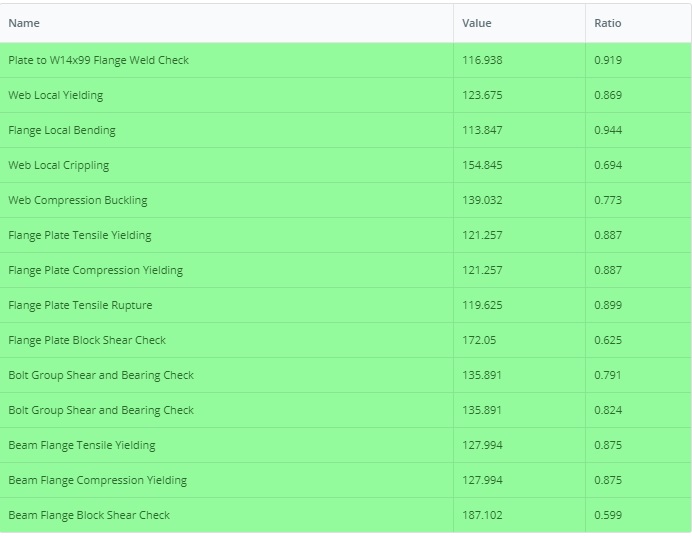
A continuación se muestra la tabla de resumen del módulo de diseño de conexión SkyCiv de todas las comprobaciones de diseño necesarias completadas para esta conexión. No todas estas comprobaciones se muestran en este artículo, pero están disponibles en PDF que puede descargar aquí.: Informe-Diseño-Conexión-EJEMPLO II.B-1-ASD
De los controles elaborados anteriormente, La flexión local de la brida gobierna en 0.944. Ese es el que hay que observar si el momento final de la viga crece., y es una propiedad de columna, por lo que una placa de brida más pesada no ayudaría.
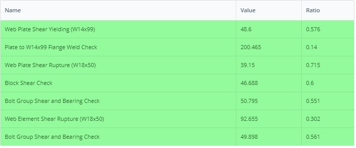
De igual forma, el ejemplo de la versión LRFD se puede encontrar en este enlace: Informe de diseño de conexión EJEMPLO II.B-1-LRFD
Ejecute este ejemplo usted mismo
Introduzca el W18x50, el W14x99 y las placas de brida, y el módulo devuelve cada verificación anterior con su índice de utilización y la cláusula detrás de ella. Se ejecuta en el navegador., sin nada que instalar.

Referencias
- AISC 360-16, Especificación para edificios de acero estructural
- Ejemplos de diseño AISC v14.1 (EJEMPLO II.B-1, páginas IIB-2 a 13)
- Software de diseño de conexión SkyCiv: https://skyciv.com/structural-software/connection-design/
- Calculadora de conexión de placa de brida: https://skyciv.com/structural-software/connection-design/flange-plate-connection-calculator/
