Ejemplo de diseño de placa base usando EN 1993-1-8:2005, EN 1993-1-1:2005, EN 1992-1-1:2004, y EN 1992-4:2018.
Declaración del problema
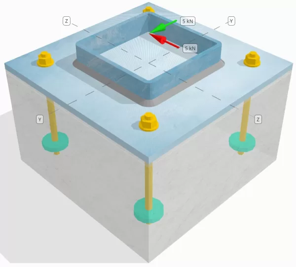
Determinar si la conexión de placa de columna a base diseñada es suficiente para un Vy=5 kN y Vz=5-kN cargas de corte.
Datos dados
Columna:
Sección de columna: SSH 180x180x8
Área de columna: 5440 mm2
Material de columna: S235
Plato base:
Dimensiones de placa base: 350 mm x 350 mm
Espesor de la placa base: 12 mm
Material de placa base: S235
Lechada:
Espesor de la lechada: 6 mm
material de lechada: ≥ 30 MPa
Hormigón:
Dimensiones concretas: 350 mm x 350 mm
Espesor de concreto: 350 mm
Material de hormigón: C25/30
Agrietado o sin crack: Agrietado
Ancla:
Diámetro de anclaje: 12 mm
Longitud de incrustación efectiva: 150 mm
Diámetro de placa incrustada: 60 mm
Espesor de la placa incrustada: 10 mm
Material de anclaje: 8.8
Otra información:
- Anclajes no comisionados.
- Ancla con hilos cortados.
- Factor K7 para falla por corte del acero del anclaje: 1.0
- Grado de restricción del sujetador: Sin restricciones
Soldaduras:
Tipo de soldadura: Soldadura de filete
Tamaño de la pierna de soldadura: 8mm
Clasificación de metal de relleno: E35
Aniquilar datos (de Calculadora de SkyCiv):
Modelo en la herramienta gratuita SkyCiv
Modele el diseño de la placa base anterior utilizando nuestra herramienta gratuita en línea hoy! No es necesario registrarse.
Definiciones
Ruta de carga:
El Software de diseño de placa base SkyCiv sigue EN 1992-4:2018 para diseño de varilla de anclaje. Las cargas de corte aplicadas a la columna se transfieren a la placa base a través de las soldaduras y luego al hormigón de soporte a través de las varillas de anclaje.. Las orejetas de fricción y corte no se consideran en este ejemplo, Como estos mecanismos no son compatibles con el software actual.
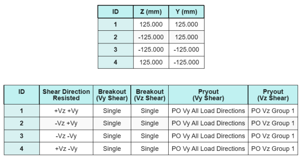
Grupos de anclaje:
El software incluye una función intuitiva que identifica qué anclajes forman parte de un grupo de anclajes para evaluar ruptura de corte de hormigón y cizalla de hormigón fallas.
Un grupo de ancla se define como dos o más anclajes con áreas de resistencia proyectadas superpuestas. En este caso, Los anclajes actúan juntos, y su resistencia combinada se verifica contra la carga aplicada en el grupo.
A un solo ancla se define como un ancla cuya área de resistencia proyectada no se superpone con ningún otro. En este caso, El ancla actúa solo, y la fuerza de corte aplicada sobre ese ancla se verifica directamente contra su resistencia individual.
Esta distinción permite que el software capture tanto el comportamiento del grupo como el rendimiento de anclaje individual al evaluar los modos de falla relacionados con el corte..
Cálculos paso a paso
Cheque #1: Calcular la capacidad de soldadura
Asumimos que el Vz La carga de corte es resistida por el soldaduras superior e inferior, mientras que la Vy La carga de corte es resistida exclusivamente por el soldaduras izquierda y derecha.
Para determinar la capacidad de soldadura del soldaduras superior e inferior, Primero calculamos su longitudes totales de soldadura.
\(
L_{w,cima&inferior} = 2 \izquierda(B_{columna} – 2A continuación se muestra un ejemplo de algunos cálculos de placa base australianos que se usan comúnmente en el diseño de placa base{columna} – 2r_{columna}\verdad)
= 2 \veces left(180 \,\texto{mm} – 2 \veces 8 \,\texto{mm} – 2 \veces 4 \,\texto{mm}\verdad)
= 312 \,\texto{mm}
\)
próximo, calculamos el tensiones en las soldaduras.
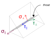
Tenga en cuenta que el corte Vz aplicado actúa paralelo al eje de soldadura., sin otras fuerzas presentes. Esto significa que las tensiones perpendiculares se pueden tomar como cero., y solo el esfuerzo cortante en la dirección paralela necesita ser calculado.
\(
\sigma_{\perpetrador} = frac{norte}{(L_{w,cima&inferior})\,asqrt{2}}
= frac{0 \,\texto{kN}}{(312 \,\texto{mm}) \veces 5.657 \,\texto{mm} \veces sqrt{2}}
= 0
\)
\(
\tu_{\perpetrador} = frac{0}{(L_{w,cima&inferior})\,asqrt{2}}
= frac{0 \,\texto{kN}}{(312 \,\texto{mm}) \veces 5.657 \,\texto{mm} \veces sqrt{2}}
= 0
\)
\(
\tu_{\paralelo} = frac{V_{z}}{(L_{w,cima&inferior})\,a}
= frac{5 \,\texto{kN}}{(312 \,\texto{mm}) \veces 5.657 \,\texto{mm}}
= 2.8329 \,\texto{MPa}
\)
Utilizando EN 1993-1-8:2005, Eq. 4.1, La tensión de soldadura de diseño se obtiene utilizando el método direccional..
\(
F_{w,Ed1} = sqrt{ (\sigma_{\perpetrador})^ 2 + 3 \izquierda( (\tu_{\perpetrador})^ 2 + (\tu_{\paralelo})^2 Derecha) }
= sqrt{ (0)^ 2 + 3 \veces left( (0)^ 2 + (2.8329 \,\texto{MPa})^2 Derecha) }
= 4.9067 \,\texto{MPa}
\)
Adicionalmente, la tensión normal de diseño para el control del metal base, por EN 1993-1-8:2005, Eq. 4.1, se toma como cero, ya que sin estrés normal esta presente.
\(
F_{w,Ed2} =sigma_{\perpetrador} = 0
\)
Ahora, evalúemos la soldaduras izquierda y derecha. Como con las soldaduras superior e inferior., primero calculamos el Longitud total de soldadura.
\(
L_{w,izquierda&verdad} = 2 \izquierda(D_{columna} – 2A continuación se muestra un ejemplo de algunos cálculos de placa base australianos que se usan comúnmente en el diseño de placa base{columna} – 2r_{columna}\verdad)
= 2 \veces left(180 \,\texto{mm} – 2 \veces 8 \,\texto{mm} – 2 \veces 4 \,\texto{mm}\verdad)
= 312 \,\texto{mm}
\)
Luego calculamos los componentes de la tensiones de soldadura.
\(
\sigma_{\perpetrador} = frac{norte}{(L_{w,izquierda&verdad})\,asqrt{2}}
= frac{0 \,\texto{kN}}{(312 \,\texto{mm}) \veces 5.657 \,\texto{mm} \veces sqrt{2}}
= 0
\)
\(
\tu_{\perpetrador} = frac{0}{(L_{w,izquierda&verdad})\,asqrt{2}}
= frac{0 \,\texto{kN}}{(312 \,\texto{mm}) \veces 5.657 \,\texto{mm} \veces sqrt{2}}
= 0
\)
\(
\tu_{\paralelo} = frac{V_Y}{(L_{w,izquierda&verdad})\,a}
= frac{5 \,\texto{kN}}{(312 \,\texto{mm}) \veces 5.657 \,\texto{mm}}
= 2.8329 \,\texto{MPa}
\)
Utilizando EN 1993-1-8:2005, Eq. 4.1, Determinamos tanto la tensión de soldadura de diseño como la tensión normal de diseño para la verificación del metal base..
\(
F_{w,Ed1} = sqrt{ \izquierda( \sigma_{\perpetrador} \verdad)^ 2 + 3 \izquierda( \izquierda( \tu_{\perpetrador} \verdad)^ 2 + \izquierda( \tu_{\paralelo} \verdad)^2 Derecha) }
\)
\(
F_{w,Ed1} = sqrt{ \izquierda( 0 \verdad)^ 2 + 3 \veces left( \izquierda( 0 \verdad)^ 2 + \izquierda( 2.8329 \,\texto{MPa} \verdad)^2 Derecha) }
\)
\(
F_{w,Ed1} = 4.9067 \,\texto{MPa}
\)
El siguiente paso es identificar el que gobierna la tensión de soldadura entre las soldaduras superior/inferior y las soldaduras izquierda/derecha. Debido a que las longitudes de soldadura son iguales y las cargas aplicadas tienen la misma magnitud, las tensiones de soldadura resultantes son iguales.
\(
F_{w,Ed1} = máx(F_{w,Ed1}, \, F_{w,Ed1})
= máx(4.9067 \,\texto{MPa}, \, 4.9067 \,\texto{MPa})
= 4.9067 \,\texto{MPa}
\)
La tensión del metal base permanece cero..
\(
F_{w,Ed2} = máx(F_{w,Ed2}, \, F_{w,Ed2}) = máx(0, \, 0) = 0
\)
Ahora, calculamos la capacidad de soldadura. primero, la resistencia del filete de soldadura se calcula. Luego, la resistencia del metales comunes esta determinado. Usando EN 1993-1-8:2005, Eq. 4.1, las capacidades se calculan de la siguiente manera:
\(
F_{w,Rd1} = frac{f_u}{\beta_wizquierda(\se requiere realizar una sumatoria de momentos con respecto al punto mencionado de todas las cargas verticales{M2, soldadura}\verdad)}
= frac{360 \,\texto{MPa}}{0.8 \veces (1.25)}
= 360 \,\texto{MPa}
\)
\(
F_{w,Td2} = frac{0.9 f_u}{\se requiere realizar una sumatoria de momentos con respecto al punto mencionado de todas las cargas verticales{M2, soldadura}}
= frac{0.9 \veces 360 \,\texto{MPa}}{1.25}
= 259.2 \,\texto{MPa}
\)
Finalmente, Comparamos las tensiones de soldadura con las capacidades de soldadura., y el metal base se esfuerza con las capacidades del metal base.
Ya que 4.9067 MPa < 360 MPa y 0 MPa < 259.2 MPa, la capacidad de la conexión soldada es suficiente.
Cheque #2: Calcule la capacidad de ruptura del concreto debido a la cizalla de VY
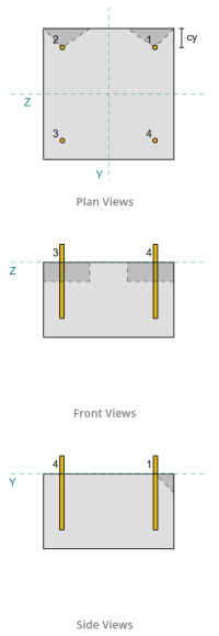
Siguiendo las disposiciones de EN 1992-4:2018, Se evalúa el borde perpendicular a la carga aplicada para detectar falla por rotura por corte.. Sólo el anclajes más cercanos a este borde se consideran comprometidos, mientras que se supone que los anclajes restantes no resisten el corte.
Estos anclajes de borde deben tener una distancia al borde del concreto mayor que 10·hef y 60·d, el mayor., dónde tener es la longitud de empotramiento y d es el diámetro del anclaje. Si esta condición no se cumple, El espesor de la placa base debe ser inferior a 0,25·hef..
Si los requisitos en EN 1992-4:2018, Cláusula 7.2.2.5(1), no estan satisfechos, el software SkyCiv no puede continuar con las comprobaciones de diseño, y se recomienda al usuario que consulte otras normas pertinentes.
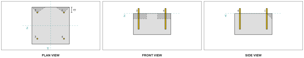
De los resultados del software SkyCiv, Los anclajes de borde actúan como anclajes individuales, ya que sus áreas proyectadas no se superponen. Para este cálculo, Ancla 1 será considerado.
Para calcular la porción de la carga de corte Vy soportada por Anchor 1, El cortante Vy total se distribuye entre los anclajes más cercanos al borde.. Esto da el fuerza perpendicular en el ancla 1.
\(
V_{\perpetrador} = frac{V_Y}{norte_{a,s}}
= frac{5 \,\texto{kN}}{2}
= 2.5 \,\texto{kN}
\)
Para el fuerza paralela, Se supone que todos los anclajes resisten la carga por igual.. Por lo tanto, la componente paralela de la carga se calcula como:
\(
V_{\paralelo} = frac{V_Z}{norte_{Congreso Nacional Africano}}
= frac{5 \,\texto{kN}}{4}
= 1.25 \,\texto{kN}
\)
El carga de corte total en el ancla 1 es por lo tanto:
\(
V_{Ed} = sqrt{ \izquierda( V_{\perpetrador} \verdad)^ 2 + \izquierda( V_{\paralelo} \verdad)^ 2 }
\)
\(
V_{Ed} = sqrt{ \izquierda( 2.5 \,\texto{kN} \verdad)^ 2 + \izquierda( 1.25 \,\texto{kN} \verdad)^ 2 } = 2.7951 \,\texto{kN}
\)
La primera parte del cálculo de capacidad es determinar la factores alfa y beta. Usamos EN 1992-4:2018, Cláusula 7.2.2.5, para establecer el si dimensión, y Ecuaciones 7.42 y 7.43 para determinar los factores.
\(
l_f = min(h_{ef}, \, 12D_{Congreso Nacional Africano})
= min(150 \,\texto{mm}, \, 12 \veces 12 \,\texto{mm})
= 144 \,\texto{mm}
\)
\(
\alfa = 0.1 \izquierda(\frac{l_f}{C_{1,s1}}\verdad)^{0.5}
= 0.1 \veces left(\frac{144 \,\texto{mm}}{50 \,\texto{mm}}\verdad)^{0.5}
= 0.16971
\)
\(
\beta = 0.1 \izquierda(\frac{D_{Congreso Nacional Africano}}{C_{1,s1}}\verdad)^{0.2}
= 0.1 \veces left(\frac{12 \,\texto{mm}}{50 \,\texto{mm}}\verdad)^{0.2}
= 0.07517
\)
El siguiente paso es calcular el valor inicial de la resistencia característica del sujetador. Utilizando EN 1992-4:2018, Ecuación 7.41, el valor es:
\(
Interacción de las fuerzas de tracción y corte del acero.{0}_ _{Rk,c} = k_9 izquierda( \frac{D_{Congreso Nacional Africano}}{\texto{mm}} \verdad)^{\alfa}
\izquierda( \frac{l_f}{\texto{mm}} \verdad)^{\beta}
\sqrt{ \frac{F_{ck}}{\texto{MPa}} }
\izquierda( \frac{C_{1,s1}}{\texto{mm}} \verdad)^{1.5} norte
\)
\(
Interacción de las fuerzas de tracción y corte del acero.{0}_ _{Rk,c} = 1.7 \veces left( \frac{12 \,\texto{mm}}{1 \,\texto{mm}} \verdad)^{0.16971}
\veces left( \frac{144 \,\texto{mm}}{1 \,\texto{mm}} \verdad)^{0.07517}
\veces sqrt{ \frac{20 \,\texto{MPa}}{1 \,\texto{MPa}} }
\veces left( \frac{50 \,\texto{mm}}{1 \,\texto{mm}} \verdad)^{1.5}
\veces 0.001 \,\texto{kN}
\)
\(
Interacción de las fuerzas de tracción y corte del acero.{0}_ _{Rk,c} = 5.954 \,\texto{kN}
\)
Luego, Calculamos el Área proyectada de referencia de un solo ancla, siguiente EN 1992-4:2018, Ecuación 7.44.
\(
UNA_{c,V }^{0} = 4.5 \izquierda( C_{1,s1} \verdad)^ 2
= 4.5 \veces left( 50 \,\texto{mm} \verdad)^ 2
= 11250 \,\texto{mm}^ 2
\)
Después, Calculamos el Área proyectada real de ancla 1.
\(
SI_{c,V } = min(C_{izquierda,s1}, \, 1.5C_{1,s1}) + \min(C_{verdad,s1}, \, 1.5C_{1,s1})
\)
\(
SI_{c,V } = min(300 \,\texto{mm}, \, 1.5 \veces 50 \,\texto{mm}) + \min(50 \,\texto{mm}, \, 1.5 \veces 50 \,\texto{mm}) = 125 \,\texto{mm}
\)
\(
se requiere realizar una sumatoria de momentos con respecto al punto mencionado de todas las cargas verticales{c,V } = min(1.5C_{1,s1}, \, A continuación se muestra un ejemplo de algunos cálculos de placa base australianos que se usan comúnmente en el diseño de placa base{sobre}) = min(1.5 \veces 50 \,\texto{mm}, \, 200 \,\texto{mm}) = 75 \,\texto{mm}
\)
\(
UNA_{c,V } La mitad de la altura de la pared desde la parte inferior de la base para el caso de la{c,V } SI_{c,V } = 75 \,\texto{mm} \veces 125 \,\texto{mm} = 9375 \,\texto{mm}^ 2
\)
También necesitamos calcular los parámetros para la rotura por corte.. Usamos EN 1992-4:2018, Ecuación 7.4, para obtener el factor que explica la alteración de la distribución del estrés, Ecuación 7.46 para el factor que explica la espesor del miembro, y Ecuación 7.48 para el factor que explica la influencia de una carga de corte inclinada hacia el borde. Estos se calculan de la siguiente manera:
\(
\Psi_{s,V } = min left( 0.7 + 0.3 \izquierda( \frac{C_{2,s1}}{1.5C_{1,s1}} \verdad), \, 1.0 \verdad)
= min left( 0.7 + 0.3 \veces left( \frac{50 \,\texto{mm}}{1.5 \veces 50 \,\texto{mm}} \verdad), \, 1 \verdad)
= 0.9
\)
\(
\Psi_{h,V } = max left( \izquierda( \frac{1.5C_{1,s1}}{A continuación se muestra un ejemplo de algunos cálculos de placa base australianos que se usan comúnmente en el diseño de placa base{sobre}} \verdad)^{0.5}, \, 1 \verdad)
= max left( \izquierda( \frac{1.5 \veces 50 \,\texto{mm}}{200 \,\texto{mm}} \verdad)^{0.5}, \, 1 \verdad)
= 1
\)
\(
\alfa_{V } = tan^{-1} \izquierda( \frac{V_{\paralelo}}{V_{\perpetrador}} \verdad)
= tan^{-1} \izquierda( \frac{1.25 \,\texto{kN}}{2.5 \,\texto{kN}} \verdad)
= 0.46365 \,\texto{trabajo}
\)
\(
\Psi_{\alfa,V } = max left(
\sqrt{ \frac{1}{(\cos(\alfa_{V }))^ 2 + \izquierda( 0.5 \, (\sin(\alfa_{V })) \verdad)^ 2 } }, \, 1 \verdad)
\)
\(
\Psi_{\alfa,V } = max left(
\sqrt{ \frac{1}{(\cos(0.46365 \,\texto{trabajo}))^ 2 + \izquierda( 0.5 \veces pecado(0.46365 \,\texto{trabajo}) \verdad)^ 2 } }, \, 1 \verdad)
\)
\(
\Psi_{\alfa,V } = 1.0847
\)
Una nota importante al determinar el factor alfa es asegurarse de que el corte perpendicular y el corte paralelo se identifiquen correctamente..
Finalmente, Calculamos el resistencia a la ruptura del ancla simple usando EN 1992-4:2018, Ecuación 7.1.
\(
V_{Rk,c} =V^0_{Rk,c} \izquierda(\frac{UNA_{c,V }}{Un^0_{c,V }}\verdad)
\Psi_{s,V } \Psi_{h,V } \Psi_{CE,V } \Psi_{\alfa,V } \Psi_{re,V }
\)
\(
V_{Rk,c} = 5.954 \,\texto{kN} \veces left(\frac{9375 \,\texto{mm}^ 2}{11250 \,\texto{mm}^ 2}\verdad)
\veces 0.9 \veces 1 \veces 1 \veces 1.0847 \veces 1
= 4.8435 \,\texto{kN}
\)
Aplicando el factor parcial, la resistencia de diseño es 3.23 kN.
\(
V_{Rd,c} = frac{V_{Rk,c}}{\se requiere realizar una sumatoria de momentos con respecto al punto mencionado de todas las cargas verticales{Mc}}
= frac{4.8435 \,\texto{kN}}{1.5}
= 3.229 \,\texto{kN}
\)
Ya que 2.7951 kN < 3.229 kN, la capacidad de ruptura de corte para corte Vy es suficiente.
Cheque #3: Calcule la capacidad de ruptura del concreto debido a la cizalla de VZ
Se utiliza el mismo enfoque para determinar la capacidad en el borde perpendicular al corte Vz..
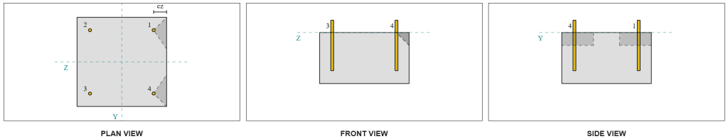
Debido al diseño simétrico, Los anclajes que resisten el corte Vz también se identifican como anclajes individuales. Consideremos Ancla 1 otra vez para los cálculos.
Para calcular el carga perpendicular en el ancla 1, dividimos el corte Vz por el número total de anclajes más cercanos al borde únicamente. Para calcular el carga paralela en el ancla 1, dividimos el cortante Vy por el número total de anclajes.
\(
V_{\perpetrador} = frac{V_{z}}{norte_{a,s}}
= frac{5 \,\texto{kN}}{2}
= 2.5 \,\texto{kN}
\)
\(
V_{\paralelo} = frac{V_{y}}{norte_{Congreso Nacional Africano}}
= frac{5 \,\texto{kN}}{4}
= 1.25 \,\texto{kN}
\)
\(
V_{Ed} = sqrt{ \izquierda( V_{\perpetrador} \verdad)^ 2 + \izquierda( V_{\paralelo} \verdad)^ 2 }
\)
\(
V_{Ed} = sqrt{ \izquierda( 2.5 \,\texto{kN} \verdad)^ 2 + \izquierda( 1.25 \,\texto{kN} \verdad)^ 2 }
= 2.7951 \,\texto{kN}
\)
Usando un enfoque similar a Check #2, el resultado resistencia a la ruptura para el borde perpendicular al corte Vz es:
\(
V_{Rd,c} = frac{V_{Rk,c}}{\se requiere realizar una sumatoria de momentos con respecto al punto mencionado de todas las cargas verticales{Mc}}
= frac{4.8435 \,\texto{kN}}{1.5}
= 3.229 \,\texto{kN}
\)
Ya que 2.7951 kN < 3.229 kN, la capacidad de ruptura de corte para corte Vz es suficiente.
Cheque #4: Calcular la capacidad de priout de concreto
El cálculo para el resistencia al corte implica determinar la Capacidad nominal de los anclajes contra rotura de tensión.. La referencia para la capacidad de ruptura de tensión es EN 1992-4:2018, Cláusula 7.2.1.4. Una discusión detallada sobre la ruptura de la tensión ya se trata en el Ejemplo de diseño SkyCiv con carga de tensión y no se repetirá en este ejemplo de diseño.
De los cálculos del software SkyCiv, la capacidad nominal de la sección para ruptura de tensión es 44.61 kN.
Luego usamos EN 1992-4:2018, Ecuación 7.39a, para obtener la resistencia característica de diseño. Utilizando k8 = 2, la capacidad es 59.48 kN.
\(
V_{Rd,cp} = frac{k_8 N_{cbg}}{\Gamma_c}
= frac{2 \veces 44.608 \,\texto{kN}}{1.5}
= 59.478 \,\texto{kN}
\)
En el control de cizallamiento, todos los anclajes son efectivos para resistir la carga de corte total. De la imagen generada por el software SkyCiv., todas las proyecciones del cono de falla se superponen entre sí, hacer que los anclajes actúen como grupo de ancla.
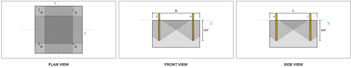
Por lo tanto, La resistencia requerida del grupo de anclaje es la carga de corte total resultante de 7.07 kN.
\(
V_{res} = sqrt{(V_Y)^ 2 + (V_Z)^ 2}
= sqrt{(5 \,\texto{kN})^ 2 + (5 \,\texto{kN})^ 2}
= 7.0711 \,\texto{kN}
\)
\(
V_{Ed} = left(\frac{V_{res}}{norte_{Congreso Nacional Africano}}\verdad) norte_{a,G1}
= left(\frac{7.0711 \,\texto{kN}}{4}\verdad) \veces 4
= 7.0711 \,\texto{kN}
\)
Ya que 7.0711 kN < 59.478 kN, la capacidad de extracción por corte es suficiente.
Cheque #5: Calcular la capacidad de corte de la barra de anclaje
El cálculo de la capacidad de corte de la varilla de anclaje depende de si la carga de corte se aplica con un brazo de momento.. Para determinar esto, Nos referimos a EN 1992-4:2018, Cláusula 6.2.2.3, donde el espesor y el material de la lechada, el número de sujetadores en el diseño, el espaciado de los sujetadores, y se verifican otros factores.
El Software de diseño de placa base de SkyCiv realiza todas las comprobaciones necesarias para determinar si el La carga de corte actúa con o sin brazo de palanca.. Para este ejemplo de diseño, se determina que la carga de corte es no aplicado con un brazo de palanca. Por lo tanto, usamos EN 1992-4:2018, Cláusula 7.2.2.3.1, para las ecuaciones de capacidad.
Comenzamos calculando la resistencia característica del sujetador de acero usando EN 1992-4:2018, Ecuación 7.34.
\(
V^0_{Rk,s} = k_6 A_s f_{tu,Congreso Nacional Africano}
= 0.5 \veces 113.1 \,\texto{mm}^2 veces 800 \,\texto{MPa}
= 45.239 \,\texto{kN}
\)
próximo, aplicamos el factor para el ductilidad del ancla única o del grupo de anclas, tomando k7 = 1.
\(
V_{Rk,s} =k_7V^{0}_ _{Rk,s}
= 1 \veces 45.239 \,\texto{kN}
= 45.239 \,\texto{kN}
\)
Luego obtenemos el factor parcial para falla por corte del acero usando EN 1992-4:2018, Tabla 4.1. Para un ancla con 8.8 material, el factor parcial resultante es:
\(
\se requiere realizar una sumatoria de momentos con respecto al punto mencionado de todas las cargas verticales{Milisegundo,el cortante}
= max left( 1.0 \izquierda( \frac{F_{tu,Congreso Nacional Africano}}{F_{y,Congreso Nacional Africano}} \verdad), \, 1.25 \verdad)
= max left( 1 \veces frac{800 \,\texto{MPa}}{640 \,\texto{MPa}}, \, 1.25 \verdad)
= 1.25
\)
Aplicando este factor a la resistencia característica., la resistencia de diseño es 36.19 kN.
\(
V_{Rd,s} = frac{V_{Rk,s}}{\se requiere realizar una sumatoria de momentos con respecto al punto mencionado de todas las cargas verticales{Milisegundo,el cortante}}
= frac{45.239 \,\texto{kN}}{1.25}
= 36.191 \,\texto{kN}
\)
El resistencia al corte requerida por varilla de anclaje es la carga de corte resultante dividida por el número total de varillas de anclaje, que se calcula para 1.77 kN.
\(
V_{Ed} = frac{\sqrt{ (V_Y)^ 2 + (V_Z)^ 2 }}{norte_{Congreso Nacional Africano}}
\)
\(
V_{Ed} = frac{\sqrt{ (5 \,\texto{kN})^ 2 + (5 \,\texto{kN})^ 2 }}{4}
= 1.7678 \,\texto{kN}
\)
Ya que 1.7678 kN < 36.191 kN, La capacidad de corte del acero de la varilla de anclaje es suficiente.
Cheque #6: Calcular la capacidad de carga de la placa base
Un adicional de Comprobación de la resistencia del rodamiento de la placa base. se introdujo en una actualización posterior del software. Por favor consulte este enlace para un cálculo de muestra y una explicación detallada.
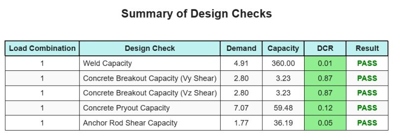
Resumen de diseño
El Software de diseño de placa base de SkyCiv puede generar automáticamente un informe de cálculo paso a paso para este ejemplo de diseño. También proporciona un resumen de los controles realizados y sus proporciones resultantes, Hacer que la información sea fácil de entender de un vistazo. A continuación se muestra una tabla de resumen de muestra, que se incluye en el informe.
Informe de muestra de SkyCiv
Vea el nivel de detalle y claridad que puede esperar de un informe de diseño de placa base SkyCiv. El informe incluye todas las comprobaciones de diseño clave., ecuaciones, y resultados presentados en un formato claro y fácil de leer. Cumple totalmente con los estándares de diseño.. Haga clic a continuación para ver un informe de muestra generado con la calculadora de placa base SkyCiv.
Comprar software de placa base
Compre la versión completa del módulo de diseño de la placa base por sí solo sin ningún otro módulo SkyCiv. Esto le da un conjunto completo de resultados para el diseño de placa base, incluyendo informes detallados y más funcionalidad.