Ejemplo de diseño de placa base usando AISC 360-22 y ACI 318-19
Declaración del problema
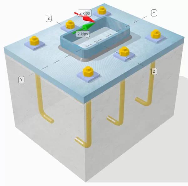
Determinar si la conexión de placa de columna a base diseñada es suficiente para un Vy = 2-kip y VZ = 2 pollo cargas de corte.
Datos dados
Columna:
Sección de columna: HSS7X4X5/16
Área de columna: 7.59 in2
Material de columna: A36
Plato base:
Dimensiones de placa base: 12 en x 14 in
Espesor de la placa base: 3/4 in
Material de placa base: A36
Lechada:
Espesor de la lechada: 0.25 in
Hormigón:
Dimensiones concretas: 12 en x 14 in
Espesor de concreto: 10 in
Material de hormigón: 3000 psi
Agrietado o sin crack: Agrietado
Ancla:
Diámetro de anclaje: 1/2 in
Longitud de incrustación efectiva: 8 in
Espesor de lavadora de placa: 0.25 in
Conexión de lavadora de placa: Soldado a la placa base
Soldaduras:
Tamaño de soldadura: 1/4 in
Clasificación de metal de relleno: E70XX
Aniquilar datos (de Calculadora de SkyCiv):
Modelo en la herramienta gratuita SkyCiv
Modele el diseño de la placa base anterior utilizando nuestra herramienta gratuita en línea hoy! No es necesario registrarse.
Definiciones
Ruta de carga:
El diseño sigue las recomendaciones de Guía de diseño AISC 1, 3edición RD, y ACI 318-19. Las cargas de corte aplicadas a la columna se transfieren a la placa base a través de las soldaduras, y luego al concreto de apoyo a través del barras de anclaje. Las orejetas de fricción y corte no se consideran en este ejemplo, Como estos mecanismos no son compatibles con el software actual.
Por defecto, el aplicado La carga de corte se distribuye a todos los anclajes., ya sea mediante el uso de arandelas de placas soldadas o por otros medios de ingeniería. La carga soportada por cada anclaje se determina utilizando los tres (3) casos indicados en ACI 318-19 Cláusula 17.7.2 y higo. R17.7.2.1b. Luego, cada anclaje transfiere la carga al hormigón de soporte que se encuentra debajo.. La distribución de carga de acuerdo con estas referencias también se utiliza al comprobar la resistencia al corte del acero del anclaje para garantizar la continuidad en los supuestos de transferencia de carga..
Como alternativa, El software permite una suposición simplificada y más conservadora, donde toda la carga de corte se asigna solo a la anclajes más cercanos al borde cargado. En este caso, La verificación de la capacidad de corte se realiza solo en estos anclajes de borde.
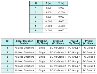
Grupos de anclaje:
El Software de diseño de placa base SkyCiv Incluye una característica intuitiva que identifica qué anclajes son parte de un grupo de anclaje para evaluar ruptura de corte de hormigón y cizalla de hormigón fallas.
Un grupo de ancla se define como dos o más anclajes con áreas de resistencia proyectadas superpuestas. En este caso, Los anclajes actúan juntos, y su resistencia combinada se verifica contra la carga aplicada en el grupo.
A un solo ancla se define como un ancla cuya área de resistencia proyectada no se superpone con ningún otro. En este caso, El ancla actúa solo, y la fuerza de corte aplicada sobre ese ancla se verifica directamente contra su resistencia individual.
Esta distinción permite que el software capture tanto el comportamiento del grupo como el rendimiento de anclaje individual al evaluar los modos de falla relacionados con el corte..
Cálculos paso a paso
Cheque #1: Calcular la capacidad de soldadura
El primer paso es calcular el Longitud total de soldadura Disponible para resistir el corte. Dado que la placa base está soldada a lo largo del perímetro de la sección de la columna, La longitud total de la soldadura se obtiene sumando las soldaduras en todos los lados.
\( L_{soldar} = 2 \izquierda( B_{columna} – 2r_{columna} – 2A continuación se muestra un ejemplo de algunos cálculos de placa base australianos que se usan comúnmente en el diseño de placa base{columna} \verdad) + 2 \izquierda( D_{columna} – 2r_{columna} – 2A continuación se muestra un ejemplo de algunos cálculos de placa base australianos que se usan comúnmente en el diseño de placa base{columna} \verdad) \)
\( L_{soldar} = 2 \veces (4\,\texto{in} – 2 \Times 0.291 , texto{in} – 2 \Times 0.291 , texto{in}) + 2 \veces (7\,\texto{in} – 2 \Times 0.291 , texto{in} – 2 \Times 0.291 , texto{in}) = 17.344 , texto{in} \)
Usando esta longitud de soldadura, las fuerzas de corte aplicadas en la y- y las direcciones z se dividen para determinar el promedio fuerza de corte por unidad de longitud en cada dirección:
\( A continuación se muestra un ejemplo de algunos cálculos de placa base australianos que se usan comúnmente en el diseño de placa base{uy} = frac{V_Y}{L_{soldar}} = frac{2\,\texto{kip}}{17.344\,\texto{in}} = 0.11531 , text{kip/in} \)
\( A continuación se muestra un ejemplo de algunos cálculos de placa base australianos que se usan comúnmente en el diseño de placa base{a} = frac{V_Z}{L_{soldar}} = frac{2\,\texto{kip}}{17.344\,\texto{in}} = 0.11531 , text{kip/in} \)
El cizalla resultante demanda por unidad de longitud luego se determina usando la raíz cuadrada de la suma de los cuadrados (SRSS) método.
\( r_u = sqrt{(A continuación se muestra un ejemplo de algunos cálculos de placa base australianos que se usan comúnmente en el diseño de placa base{uy})^ 2 + (A continuación se muestra un ejemplo de algunos cálculos de placa base australianos que se usan comúnmente en el diseño de placa base{a})^ 2} \)
\( r_u = sqrt{(0.11531\,\texto{kip/in})^ 2 + (0.11531\,\texto{kip/in})^ 2} = 0.16308 , texto{kip/in} \)
próximo, la capacidad de soldadura se calcula utilizando AISC 360-22 Eq. J2-4, con el coeficiente de resistencia direccional tomado como kds = 1.0 para una sección HSS. La capacidad de soldadura para un 1/4 en la soldadura se determina como:
\( \Phi r_n = phi 0.6 F_{Exx} E_w k_{ds} = 0.75 \veces 0.6 \Times 70 , texto{KSI} \Times 0.177 , texto{in} \veces 1 = 5.5755 , text{kip/in} \)
También es necesario verificar los metales base, Tanto la columna como la placa base, usando AISC 360-22 Eq. J4-4 Para obtener la resistencia a la ruptura de corte. Esto da:
\( \Phi R_{Nbm, columna} = phi 0.6 F_{u _col} A continuación se muestra un ejemplo de algunos cálculos de placa base australianos que se usan comúnmente en el diseño de placa base{columna} = 0.75 \veces 0.6 \Times 58 , texto{KSI} \Times 0.291 , texto{in} = 7.5951 , text{kip/in} \)
\( \Phi R_{Nbm, pb} = phi 0.6 F_{U _BP} A continuación se muestra un ejemplo de algunos cálculos de placa base australianos que se usan comúnmente en el diseño de placa base{pb} = 0.75 \veces 0.6 \Times 58 , texto{KSI} \Times 0.75 , texto{in} = 19.575 , texto{kip/in} \)
\( \Phi R_{Nbm} = min izquierda( \Phi R_{Nbm, pb},\, \Phi R_{Nbm, columna} \verdad) = min(19.575\,\texto{kip/in},\, 7.5951\,\texto{kip/in}) = 7.5951 , text{kip/in} \)
Dado que la tensión de soldadura real es menor que las capacidades de metal de soldadura y de metal base, 0.16308 KPI < 5.5755 KPI y 0.16308 KPI < 7.5951 KPI, La capacidad de soldadura de diseño es suficiente.
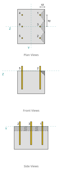
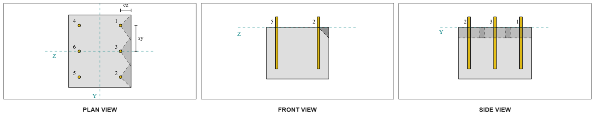
Cheque #2: Calcule la capacidad de ruptura del concreto debido a la cizalla de VY
Capacidad de borde perpendicular:
Del diseño, Ancla 1 y 4 están más cerca del borde y tienen el Distancia más corta de CA1. Uso de estos valores de CA1 para proyectar los conos de falla, El software identificó estos anclajes como anclajes individuales, Dado que sus conos proyectados no se superponen. El apoyo también se determinó que no era un miembro estrecho, Entonces la distancia CA1 se usa directamente sin modificación.
Recordemos que se supone que la fuerza de corte se distribuye entre todos los anclajes. El cálculo para el Carga de cizallas VY aplicado a cada ancla de un solo es:
\( V_{Fa perp} = frac{V_Y}{n / A} = frac{2\,\texto{kip}}{6} = 0.333333 , text{kip} \)
Consideremos Ancla 1. El área máxima proyectada de un solo ancla se calcula utilizando ACI 318-19 Eq. 17.7.2.1.3.
\( UNA_{vco} = 4.5 (C_{A1, S1})^2 = 4.5 \veces (2\,\texto{in})^2 = 18 , texto{in}^ 2 \)
El área proyectada real se determina a partir del ancho y la altura del cono de falla proyectado.
\( SI_{U} = min(C_{izquierda,s1},\, 1.5C_{A1, S1}) + \min(C_{verdad,s1},\, 1.5C_{A1, S1}) \)
\( SI_{U} = min(10\,\texto{in},\, 1.5 \Times 2 , texto{in}) + \min(2\,\texto{in},\, 1.5 \Times 2 , texto{in}) = 5 , texto{in} \)
\( se requiere realizar una sumatoria de momentos con respecto al punto mencionado de todas las cargas verticales{U} = min(1.5C_{A1, S1},\, A continuación se muestra un ejemplo de algunos cálculos de placa base australianos que se usan comúnmente en el diseño de placa base{sobre}) = min(1.5 \Times 2 , texto{in},\, 10\,\texto{in}) = 3 , texto{in} \)
\( UNA_{U} = B_{U} se requiere realizar una sumatoria de momentos con respecto al punto mencionado de todas las cargas verticales{U} = 5 , texto{in} \Times 3 , texto{in} = 15 , texto{in}^ 2 \)
El siguiente paso es usar Ecuaciones 17.7.2.2.1a y 17.7.2.2.1b Para calcular la fuerza de ruptura básica de un solo ancla. La capacidad de gobierno se toma como el valor menor.
\( V_{b1} = 7 \izquierda( \frac{\min(el,\, 8D_A)}{D_A} \verdad)^{0.2} \sqrt{\frac{D_A}{\texto{in}}} \lambda_a sqrt{\frac{f’_c}{\texto{psi}}} \izquierda( \frac{C_{A1, S1}}{\texto{in}} \verdad)^{1.5} \,\texto{lbf} \)
\( V_{b1} = 7 \veces left( \frac{\min(8\,\texto{in},\, 8 \Times 0.5 , texto{in})}{0.5\,\texto{in}} \verdad)^{0.2} \veces sqrt{\frac{0.5\,\texto{in}}{1\,\texto{in}}} \veces 1 \veces sqrt{\frac{3\,\texto{KSI}}{0.001\,\texto{KSI}}} \veces left( \frac{2\,\texto{in}}{1\,\texto{in}} \verdad)^{1.5} \Times 0.001 , texto{kip} \)
\( V_{b1} = 1.1623 , text{kip} \)
\( V_{b2} = 9 \lambda_a sqrt{\frac{f’_c}{\texto{psi}}} \izquierda( \frac{C_{A1, S1}}{\texto{in}} \verdad)^{1.5} \,\texto{lbf} \)
\( V_{b2} = 9 \veces 1 \veces sqrt{\frac{3\,\texto{KSI}}{0.001\,\texto{KSI}}} \veces left( \frac{2\,\texto{in}}{1\,\texto{in}} \verdad)^{1.5} \Times 0.001 , texto{kip} = 1.3943 , text{kip} \)
\( V_b = min(V_{b1},\, V_{b2}) = min(1.1623\,\texto{kip},\, 1.3943\,\texto{kip}) = 1.1623 , text{kip} \)
próximo, la Parámetros de capacidad de ruptura están determinados. El Factor de efecto de borde de ruptura se calcula de acuerdo con ACI 318-19 Cláusula 17.7.2.4, y el Factor de grosor se calcula de acuerdo con Cláusula 17.7.2.6.1.
\( \Psi_{ed,V } = min izquierda(1.0,\, 0.7 + 0.3 \izquierda( \frac{C_{A2, S1}}{1.5C_{A1, S1}} \verdad) \verdad) = min izquierda(1,\, 0.7 + 0.3 \veces left( \frac{2\,\texto{in}}{1.5 \Times 2 , texto{in}} \verdad) \verdad) = 0.9 \)
\( \Psi_{h,V } = max izquierda( \sqrt{ \frac{1.5C_{A1, S1}}{A continuación se muestra un ejemplo de algunos cálculos de placa base australianos que se usan comúnmente en el diseño de placa base{sobre}} },\, 1.0 \verdad) = max izquierda( \sqrt{ \frac{1.5 \Times 2 , texto{in}}{10\,\texto{in}} },\, 1 \verdad) = 1 \)
Finalmente, ACI 318-19 Cláusula 17.7.2.1(a) se usa para determinar la capacidad de ruptura de concreto de un solo ancla. La capacidad calculada para la cizalla vy en la dirección perpendicular es 0.69 kips .
\( \no V_{CB Perp} = phi izquierda( \frac{UNA_{U}}{UNA_{vco}} \verdad) \Psi_{ed,V } \Psi_{c,V } \Psi_{h,V } V_B \)
\( \no V_{CB Perp} = 0.65 \veces left( \frac{15\,\texto{in}^ 2}{18\,\texto{in}^ 2} \verdad) \veces 0.86 \veces 1 \veces 1 \Times 1.1623 , texto{kip} = 0.56661 , text{kip} \)
La capacidad calculada para Vy Shear en el perpendicular la dirección es 0.56 kips .
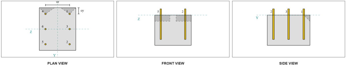
Capacidad de borde paralelo:
La falla a lo largo del borde paralela a la carga también es posible en este escenario, entonces el Capacidad de ruptura de concreto para el borde paralelo debe ser determinado. Los anclajes o el grupo de anclaje considerados son los alineados con el borde paralelo. Por consiguiente, la CA1 La distancia del borde se mide desde el ancla hasta el borde a lo largo de la dirección z. Basado en la figura a continuación, Las proyecciones de cono de falla se superponen; por lo tanto, Los anclajes son tratados como un grupo.
Caso 1:
Caso 2:
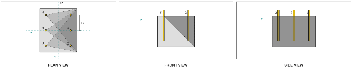
Nos referimos a ACI 318-19 Fig. R17.7.2.1b Para los diferentes casos utilizados al evaluar grupos de anclaje. En este diseño de placa base, arandelas de placa soldadas se utilizan específicamente. Por lo tanto, solo Caso 2 se revisa.
La carga requerida para el grupo de anclaje en el caso 2 se toma como el carga de corte total.
\( V_{fa paralelo,Caso2} = V_y = 2 , text{kip} \)
Al calcular la capacidad del caso 2 falla, Los anclajes considerados son el anclajes traseros. Como resultado, La distancia del borde CA1 se mide desde el grupo de anclaje trasero hasta el borde de falla.
Con esta orientación de distancia y borde de CA1, debe verificarse si el soporte califica como miembro estrecho. Siguiente ACI 318-19 Cláusula 17.7.2.1.2, El software SkyCiv Base Plate identificó el soporte como angosto. Por lo tanto, la distancia modificada de CA1 se usa, que se calcula como 6.667 in.
Se siguen los mismos pasos que en el caso perpendicular: calculando el áreas de falla proyectadas, la Fuerza de ruptura básica de un solo ancla, y el Parámetros de ruptura. Los valores calculados para cada paso se muestran a continuación.
\( UNA_{vco} = 4.5 (C_{‘A1, G2})^2 = 4.5 \veces (6.6667\,\texto{in})^2 = 200 , texto{in}^ 2 \)
\( UNA_{U} = B_{U} se requiere realizar una sumatoria de momentos con respecto al punto mencionado de todas las cargas verticales{U} = 14 , texto{in} \Times 10 , texto{in} = 140 , texto{in}^ 2 \)
\( V_{b1} = 7.0733 , text{kip} \)
\( V_{b2} = 8.4853 , text{kip} \)
\( V_b = min(V_{b1},\, V_{b2}) = min(7.0733\,\texto{kip},\, 8.4853\,\texto{kip}) = 7.0733 , text{kip} \)
\( \Psi_{ed,V } = 1.0 \)
\( \Psi_{h,V } = 1.0 \)
La ecuación para la capacidad del borde paralelo difiere de la capacidad del borde perpendicular. ACI 318-19 Cláusula 17.7.2.1(c) se aplica, donde esta la ecuación de ruptura está multiplicado por 2.
\( \no V_{CBG paralelo} = 2 \Phi Izquierda( \frac{UNA_{U}}{UNA_{vco}} \verdad) \Psi_{ed,V } \Psi_{c,V } \Psi_{h,V } V_B \)
\( \no V_{CBG paralelo} = 2 \veces 0.65 \veces left( \frac{140\,\texto{in}^ 2}{200\texto{in}^ 2} \verdad) \veces 1 \veces 1 \veces 1 \Times 7.0733 , texto{kip} = 6.4367 , text{kip} \)
La capacidad calculada para Vy Shear en el paralelo la dirección es 6.43 kips .
Ahora evaluamos las fallas perpendiculares y paralelas por separado.
- Para la falla del borde perpendicular, ya que 0.33 kip < 0.56 kip, La capacidad de ruptura de cizallamiento de concreto de diseño es suficiente.
- Para la falla del borde paralelo, ya que 2 kip < 6.43 kip, La capacidad de ruptura de cizallamiento de concreto de diseño es suficiente.
Cheque #3: Calcule la capacidad de ruptura del concreto debido a la cizalla de VZ
La placa base también está sujeta a Cizalla de vz, Por lo tanto, los bordes de falla perpendiculares y paralelos a la cizalla de VZ deben verificarse. Usando el mismo enfoque, Las capacidades perpendiculares y paralelas se calculan como 2.45 kips y 1.26 kips , respectivamente.
Borde perpendicular:
Borde paralelo:
Estas capacidades se comparan con las fortalezas requeridas..
- Para la falla del borde perpendicular, ya que 2 kip < 2.45 kip, La capacidad de ruptura de corte de hormigón es suficiente.
- Para la falla del borde paralelo, ya que 0.33 kip < 1.26 kip, La capacidad de ruptura de corte de hormigón es suficiente.
Cheque #4: Calcular la capacidad de priout de concreto
El Cono de concreto para falla de Pryout es el mismo cono utilizado en la verificación de ruptura de la tracción. Para calcular la capacidad de cizalla, La resistencia de ruptura de tracción nominal de los anclajes individuales o el grupo de anclaje debe determinarse primero. Los cálculos detallados para la verificación de ruptura de la tracción ya están cubiertos en el Ejemplos de diseño de SkyCiv para la carga de tensión.
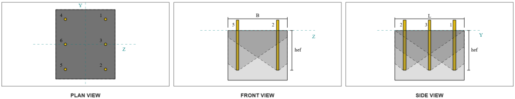
Es importante tener en cuenta que la determinación del grupo de ancla. Por lo tanto, Los anclajes en el diseño aún deben verificarse para determinar si ellos acto tener un grupo o como anclajes individuales contra la falla de cizallamiento. La clasificación del soporte como un sección estrecha también debe verificarse y debe seguir las mismas condiciones utilizadas para ruptura de tensión.
De los cálculos de SkyCiv, la Fuerza de ruptura de tracción nominal del grupo de ancla es 12.772 kips . Con un factor de pricout de KCP = 2, La capacidad de diseño de diseño es:
\( \no V_{cpg} = hy k_{cp} NORTE_{cbg} = 0.65 \veces 2 \veces 12.772 \,\texto{kip} = 16.604 , texto{kip} \)
La fuerza requerida es la resultante de las cargas de corte aplicadas. Dado que todos los anclajes pertenecen a un solo grupo, La cizalla total resultante se asigna al grupo.
\( V_{hacer} = sqrt{(V_Y)^ 2 + (V_Z)^ 2} = sqrt{(2\,\texto{kip})^ 2 + (2\,\texto{kip})^ 2} = 2.8284 , text{kip} \)
\( V_{hacer} = left( \frac{V_{hacer}}{n / A} \verdad) norte_{a,G1} = left( \frac{2.8284\,\texto{kip}}{6} \verdad) \veces 6 = 2.8284 , text{kip} \)
Dado que la carga de corte total es menor que la capacidad del grupo de anclaje, 2.82 kips < 18.976 kips , La capacidad de diseño de diseño es suficiente.
Cheque #5: Calcular la capacidad de corte de la barra de anclaje
Recuerde que en este ejemplo de diseño, La cizalla se distribuye a todos los anclajes. La carga de corte total por ancla es, por lo tanto, el resultado de su participación de la carga de VY y su participación en la carga de VZ.
\( A continuación se muestra un ejemplo de algunos cálculos de placa base australianos que se usan comúnmente en el diseño de placa base{hacer,y} = frac{V_Y}{n / A} = frac{2\,\texto{kip}}{6} = 0.333333 , text{kip} \)
\( A continuación se muestra un ejemplo de algunos cálculos de placa base australianos que se usan comúnmente en el diseño de placa base{hacer,z} = frac{V_Z}{n / A} = frac{2\,\texto{kip}}{6} = 0.333333 , text{kip} \)
\( V_{hacer} = sqrt{(A continuación se muestra un ejemplo de algunos cálculos de placa base australianos que se usan comúnmente en el diseño de placa base{hacer,y})^ 2 + (A continuación se muestra un ejemplo de algunos cálculos de placa base australianos que se usan comúnmente en el diseño de placa base{hacer,z})^ 2} \)
\( V_{hacer} = sqrt{(0.33333\,\texto{kip})^ 2 + (0.33333\,\texto{kip})^ 2} = 0.4714 , texto{kip} \)
Esto da el Tensión de corte en la barra de anclaje como:
\( f_v = frac{V_{hacer}}{UNA_{vara}} = frac{0.4714\,\texto{kip}}{0.19635\,\texto{in}^ 2} = 2.4008 , texto{KSI} \)
Porque una lavadora de placa está presente, un carga de corte excéntrica se induce en la barra de ancla. La excentricidad se toma como la mitad de la distancia medida desde la parte superior del soporte de concreto al centro de la lavadora de la placa, contabilizar el grosor de la placa base. Referirse a Guía de diseño AISC 1, 3Sección de edición RD 4.3.3.
\( e = 0.5 \izquierda( \frac{A continuación se muestra un ejemplo de algunos cálculos de placa base australianos que se usan comúnmente en el diseño de placa base{PW}}{2} + A continuación se muestra un ejemplo de algunos cálculos de placa base australianos que se usan comúnmente en el diseño de placa base{pb} \verdad) = 0.5 \veces left( \frac{0.25\,\texto{in}}{2} + 0.75\,\texto{in} \verdad) = 0.4375 , texto{in} \)
El momento de la cizalla excéntrica se expresa como un Estrés axial en la barra de anclaje. Usando el módulo de sección, La tensión axial debido a este momento se calcula como:
\( Z_{vara} = frac{\pi}{32} (D_A)^3 = frac{\pi}{32} \veces (0.5\,\texto{in})^3 = 0.012272 , texto{in}^ 3 \)
\( f_t = frac{V_{hacer} mi}{Z_{vara}} = frac{0.4714\,\texto{kip} \Times 0.4375 , texto{in}}{0.012272\,\texto{in}^ 3} = 16.806 , text{KSI} \)
Capacidad de corte de varilla de anclaje ACI ACI:
Siguiente ACI 318-19 Cláusula 17.7.1, la fuerza de diseño se determina entonces. A 0.8 factor de reducción se aplica debido a la presencia de almohadillas. La capacidad de diseño es por lo tanto:
\( \no V_{a,aquí} = 0.8 \fi 0.6 UNA_{se,v} F_{uta} = 0.8 \veces 0.65 \veces 0.6 \Times 0.1419 texto{in}^2 Times 90 Texto{KSI} = 3.9845 texto{kip} \)
Como alternativa, la Software de placa base de SkyCiv Permite el 0.8 simplificación para deshabilitar, y use el grosor real de la almohadilla de lechada en los cálculos. En este caso, La excentricidad total incluye la almohadilla de la lechada, y el corte combinado y la resistencia axial se determina de acuerdo con las disposiciones de AISC.
Capacidad de corte de barra de anclaje AISC:
primero, la tensión nominal de corte y tracción se determinan para una barra A325.
\( F_{Nevada} = 0.45 F_{tu,Congreso Nacional Africano} = 0.45 \veces 120\ \texto{KSI} = 54\ \texto{KSI} \)
\( F_{Nuevo Testamento} = 0.75 F_{tu,Congreso Nacional Africano} = 0.75 \veces 120\ \texto{KSI} = 90\ \texto{KSI} \)
El método AISC usa AISC 360-22 Eq. J3-3a, que puede expresarse para incluir los efectos del estrés axial. Esto se lleva a cabo de la siguiente manera.
\( F'_{Nevada} = min left( 1.3 F_{Nevada} – \izquierda( \frac{F_{Nevada}}{\Phi F_{Nuevo Testamento}} \verdad) pie,\; F_{Nevada} \verdad) \)
\( F'_{Nevada} = min left( 1.3 \veces 54\ \texto{KSI} – \izquierda( \frac{54\ \texto{KSI}}{0.75 \veces 90\ \texto{KSI}} \verdad) \veces 16.806\ \texto{KSI},\; 54\ \texto{KSI} \verdad) = 54\ \texto{KSI} \)
La capacidad de corte de diseño del método AISC se calcula como:
\( \fi R_{norte,\mathrm{aisc}} = Phi f’_{Nevada} UNA_{vara} = 0.75 \veces 54\ \texto{KSI} \veces 0.19635\ \texto{in}^2 = 7.9522\)
Para garantizar que ambos métodos estén cubiertos, La capacidad de gobierno se toma como la menor de los dos, que es 3.98 kip.
\( \Phi v_n = min izquierda( \no V_{a,aquí},\; \fi R_{norte,\mathrm{aisc}} \verdad) = min (3.9845\ \texto{kip},\; 7.9522\ \texto{kip}) = 3.9845\ \texto{kip} \)
Dado que la carga de corte por varilla de anclaje es menor que la capacidad de la varilla de anclaje de gobierno en cizallamiento, 0.47 kip < 3.98 kip, La capacidad de corte de barra de anclaje de diseño es suficiente.
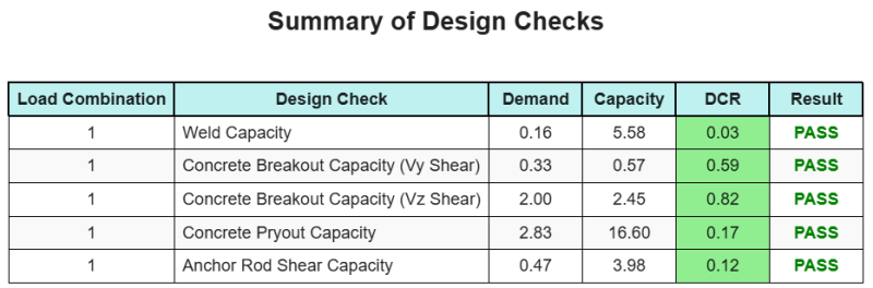
Resumen de diseño
El Software de diseño de placa base de SkyCiv puede generar automáticamente un informe de cálculo paso a paso para este ejemplo de diseño. También proporciona un resumen de los controles realizados y sus proporciones resultantes, Hacer que la información sea fácil de entender de un vistazo. A continuación se muestra una tabla de resumen de muestra, que se incluye en el informe.
Informe de muestra de SkyCiv
Vea el nivel de detalle y claridad que puede esperar de un informe de diseño de placa base SkyCiv. El informe incluye todas las comprobaciones de diseño clave., ecuaciones, y resultados presentados en un formato claro y fácil de leer. Cumple totalmente con los estándares de diseño.. Haga clic a continuación para ver un informe de muestra generado con la calculadora de placa base SkyCiv.
Comprar software de placa base
Compre la versión completa del módulo de diseño de la placa base por sí solo sin ningún otro módulo SkyCiv. Esto le da un conjunto completo de resultados para el diseño de placa base, incluyendo informes detallados y más funcionalidad.