Ejemplo de diseño de placa base utilizando CSA S16:19 y CSA A23.3:19
Declaración del problema
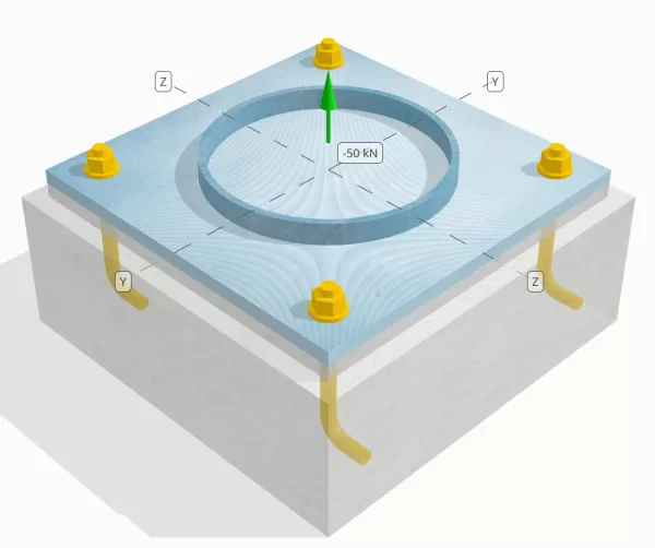
Determine si la conexión de placa de columna a base diseñada es suficiente para una carga de tensión de 50 kn..
Datos dados
Columna:
Sección de columna: HS324X9.5
Área de columna: 9410 mm2
Material de columna: 230GRAMO
Plato base:
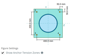
Dimensiones de placa base: 500 mm x 500 mm
Espesor de la placa base: 20 mm
Material de placa base: 230GRAMO
Lechada:
Espesor de la lechada: 20 mm
Hormigón:
Dimensiones concretas: 550 mm x 550 mm
Espesor de concreto: 200 mm
Material de hormigón: 20.68 MPa
Agrietado o sin crack: Agrietado
Ancla:
Diámetro de anclaje: 19.1 mm
Longitud de incrustación efectiva: 130.0 mm
Longitud del gancho: 60mm
Distancia de desplazamiento de anclaje desde la cara de la columna: 120.84 mm
Soldaduras:
Tipo de soldadura: CJP
Clasificación de metal de relleno: E43xx
Aniquilar datos (de Calculadora de SkyCiv):
Modelo en la herramienta gratuita SkyCiv
Modele el diseño de la placa base anterior utilizando nuestra herramienta gratuita en línea hoy! No es necesario registrarse.
Definiciones
Ruta de carga:
Cuando una placa base está sujeta a elevación (de tensión) efectivo, Estas fuerzas se transfieren a las varillas de anclaje, que a su vez inducen momentos de flexión en la placa base. La acción de flexión se puede visualizar como flexión en voladizo ocurriendo alrededor de las bridas o la web de la sección de la columna, dependiendo de dónde estén posicionados los anclajes.
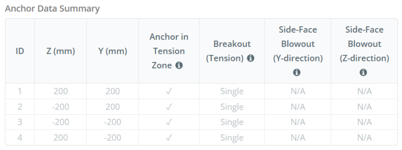
En el Software de diseño de placa base SkyCiv, solo anclajes ubicados dentro del zona de tensión de anclaje se consideran efectivos para resistir la elevación. Esta zona generalmente incluye áreas cerca de las bridas de la columna o la web.. En el caso de un columna circular, La zona de tensión de anclaje incluye toda el área fuera del perímetro de la columna. Los anclajes fuera de esta zona no contribuyen a la resistencia a la tensión y se excluyen de los cálculos de elevación.
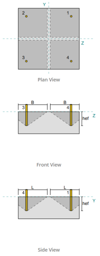
Para determinar el área efectiva de la placa base que resiste la flexión, a 45-dispersión de grado se supone desde la línea central de cada barra de anclaje hacia la cara de la columna. Esta dispersión define el longitud de soldadura efectiva y ayuda a establecer el Ancho de flexión efectivo del plato.
La suposición simplifica el análisis de la placa base al aproximar cómo la fuerza de elevación se extiende a través de la placa.
Grupos de anclaje:
El Software de diseño de placa base SkyCiv Incluye una característica intuitiva que identifica qué anclajes son parte de un grupo de anclaje para evaluar ruptura de concreto y reventón de cara lateral de concreto fallas.
Un grupo de ancla consiste en múltiples anclajes con profundidades de incrustación efectivas similares y espaciado, y están lo suficientemente cerca como para que su áreas de resistencia proyectadas superpuesto. Cuando se agrupan los anclajes, Sus capacidades se combinan para resistir la fuerza de tensión total aplicada al grupo.
Los anclajes que no cumplen con los criterios de agrupación se tratan como anclajes individuales. En este caso, Solo la fuerza de tensión sobre el ancla individual se verifica en su propio área de resistencia efectiva.
Cálculos paso a paso
Cheque #1: Calcular la capacidad de soldadura
Empezar, Necesitamos calcular la carga por ancla y determinar la longitud de soldadura efectiva para cada ancla. El longitud de soldadura efectiva se basa en un 45° línea de dispersión Dibujado del centro del ancla a la cara de la columna. Si esta línea de 45 ° no se cruza con la columna, la puntos tangentes se usan en su lugar. Adicionalmente, Si los anclajes están estrechamente espaciados, La longitud efectiva de la soldadura se reduce para evitar la superposición. Finalmente, La suma de todas las longitudes efectivas de soldadura no debe exceder la longitud soldable real disponible a lo largo de la circunferencia de la columna.
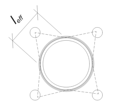
Aplicemos esto a nuestro ejemplo. Basado en la geometría dada, La línea de 45 ° desde el ancla no intersecta la columna. Como resultado, La longitud del arco entre los puntos tangentes se usa en su lugar. Esta longitud del arco también debe tener en cuenta cualquier anclaje adyacente, con cualquier porción superpuesta restada para evitar doble conteo. La longitud del arco calculado es:
\(
l_{\texto{arco}} = 254.47 \, \texto{mm}
\)
Este cálculo de longitud de arco está completamente automatizado en el software de diseño de placas base de SkyCiv., pero también se puede realizar manualmente utilizando métodos trigonométricos. Puede probar la herramienta gratuita desde este enlace.
Considerando la longitud soldable disponible a lo largo de la circunferencia de la columna, la final longitud de soldadura efectiva es:
\(
l_{\texto{efecto}} = min left( l_{\texto{arco}}, \frac{\Pi D_{\texto{columna}}}{norte_{a,t}} \verdad) = min left( 254.47 \, \texto{mm}, \frac{\Pi Times 324 \, \texto{mm}}{4} \verdad) = 254.47 \, \texto{mm}
\)
próximo, Calculemos el Carga por ancla. Para un conjunto dado de cuatro (4) anclas, La carga por ancla es:
\(
T_{tu,\texto{ancla}} = frac{N_X}{norte_{a,t}} = frac{50 \, \texto{kN}}{4} = 12.5 \, \texto{kN}
\)
Usando la longitud de soldadura efectiva calculada, Ahora podemos calcular el fuerza requerida por unidad de longitud actuando en la soldadura.
\(
v_f = frac{T_{tu,\texto{ancla}}}{l_{\texto{efecto}}} = frac{12.5 \, \texto{kN}}{254.47 \, \texto{mm}} = 0.049122 \, \texto{kN / mm}
\)
Ahora, Nos referimos a CSA S16:19 Cláusula 13.13.3.1 para calcular el Resistencia factorizada de la penetración de la articulación completa (CJP) soldar. Esto requiere la resistencia del metal base, expresado en fuerza por unidad de longitud, tanto para la columna como para los materiales de la placa base.
\(
A continuación se muestra un ejemplo de algunos cálculos de placa base australianos que se usan comúnmente en el diseño de placa base{r,\texto{bm}} = phi izquierda( \min izquierda( F_{y,\texto{columna}} A continuación se muestra un ejemplo de algunos cálculos de placa base australianos que se usan comúnmente en el diseño de placa base{\texto{columna}}, F_{y,\texto{pb}} A continuación se muestra un ejemplo de algunos cálculos de placa base australianos que se usan comúnmente en el diseño de placa base{\texto{pb}} \verdad) \verdad)
\)
\(
A continuación se muestra un ejemplo de algunos cálculos de placa base australianos que se usan comúnmente en el diseño de placa base{r,\texto{bm}} = 0.9 \veces left( \min izquierda( 230 \, \texto{MPa} \veces 9.53 \, \texto{mm}, 230 \, \texto{MPa} \veces 20 \, \texto{mm} \verdad) \verdad) = 1.9727 \, \texto{kN / mm}
\)
Ya que 0.049122 kN / mm < 1.9727 kN / mm, La capacidad de soldadura es suficiente.
Cheque #2: Calcule la capacidad de rendimiento de flexión de la placa base debido a la carga de tensión
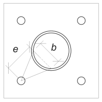
Usando la carga por ancla y el distancia de compensación desde el centro del ancla hasta la cara de la columna, El momento aplicado a la placa base se puede calcular utilizando un viga voladiza suposición. Para una columna circular, La excentricidad de la carga se determina considerando la sagita del arco soldado, y se puede calcular de la siguiente manera:
\(
mi_{\texto{tubo}} = D_O + r_{\texto{columna}} \izquierda( 1 – \porque izquierda( \frac{l_{\texto{efecto}}}{2 r_{\texto{columna}}} \verdad) \verdad)
\)
\(
mi_{\texto{tubo}} = 120.84 \, \texto{mm} + 162 \, \texto{mm} \veces left( 1 – \porque izquierda( \frac{254.47 \, \texto{mm}}{2 \veces 162 \, \texto{mm}} \verdad) \verdad) = 168.29 \, \texto{mm}
\)
El momento inducido se calcula como:
\(
M_f = t_{tu,\texto{ancla}} mi_{\texto{tubo}} = 12.5 \, \texto{kN} \veces 168.29 \, \texto{mm} = 2103.6 \, \texto{kN} \CDOT Texto{mm}
\)
próximo, Determinaremos el ancho de flexión de la placa base. Para esto, Usamos el longitud de acorde correspondiente al arco de soldadura efectivo.
\(
\theta_{\texto{trabajo}} = frac{l_{\texto{efecto}}}{0.5 D_{\texto{columna}}} = frac{254.47 \, \texto{mm}}{0.5 \veces 324 \, \texto{mm}} = 1.5708
\)
\(
B = D_{\texto{columna}} \izquierda( \pecado izquierda( \frac{\theta_{\texto{trabajo}}}{2} \verdad) \verdad) = 324 \, \texto{mm} \veces left( \pecado izquierda( \frac{1.5708}{2} \verdad) \verdad) = 229.1 \, \texto{mm}
\)
Finalmente, podemos calcular el factorizado resistencia a la flexión de la placa base usando CSA S16:19 Cláusula 13.5.
\(
M_r = phi f_{y,\texto{pb}} Z_{\texto{efecto}} = 0.9 \veces 230 \, \texto{MPa} \veces 22910 \, \texto{mm}^3 = 4742.4 \, \texto{kN} \CDOT Texto{mm}
\)
Dónde,
\(
Z_{\texto{efecto}} = frac{b (A continuación se muestra un ejemplo de algunos cálculos de placa base australianos que se usan comúnmente en el diseño de placa base{\texto{pb}})^ 2}{4} = frac{229.1 \, \texto{mm} \veces (20 \, \texto{mm})^ 2}{4} = 22910 \, \texto{mm}^ 3
\)
Ya que 2103.6 KN-MM < 4742.4 KN-MM, La capacidad de rendimiento de flexión de la placa base es suficiente.
Cheque #3: Calcular la capacidad de tracción de la barra de anclaje
Para evaluar la capacidad de tracción de la barra de anclaje, Nos referimos a CSA A23.3:19 Cláusula D.6.1.2 y CSA S16:19 Cláusula 25.3.2.1.
primero, Determinamos el resistencia a la tracción especificada del ancla de acero. Este es el valor más bajo permitido por CSA A23.3:19 Cláusula D.6.1.2.
\(
F_{\texto{uta}} = min left( F_{tu,\texto{Congreso Nacional Africano}}, 1.9 F_{y,\texto{Congreso Nacional Africano}}, 860 \verdad) = min left( 400 \, \texto{MPa}, 1.9 \veces 248.2 \, \texto{MPa}, 860.00 \, \texto{MPa} \verdad) = 400 \, \texto{MPa}
\)
próximo, Determinamos el Área transversal efectiva de la varilla de anclaje en tensión utilizando Manual de diseño de concreto CAC, 3edición RD, Tabla 12.3.
\(
UNA_{se,norte} = 215 \, \texto{mm}^ 2
\)
Con estos valores, Solicitamos CSA A23.3:19 Eq. D.2 para calcular el resistencia a la tracción factorizada de la barra de ancla.
\(
NORTE_{\texto{sar}} = A_{se,norte} \Phi_S F_{\texto{uta}} R = 215 \, \texto{mm}^2 veces 0.85 \veces 400 \, \texto{MPa} \veces 0.8 = 58.465 \, \texto{kN}
\)
Adicionalmente, Evaluamos el resistencia a la tracción factorizada de acuerdo a CSA S16:19 Cláusula 25.3.2.1.
\(
T_r = phi_{Arkansas} 0.85 UNA_{Arkansas} F_{tu,\texto{Congreso Nacional Africano}} = 0.67 \veces 0.85 \veces 285.02 \, \texto{mm}^2 veces 400 \, \texto{MPa} = 64.912 \, \texto{kN}
\)
Después de comparar los dos, Identificamos que la resistencia factorizada calculada usando CSA A23.3:19 gobierna en este caso.
Recuerde el previamente calculado carga de tensión por ancla:
\(
NORTE_{fa} = frac{N_X}{norte_{a,t}} = frac{50 \, \texto{kN}}{4} = 12.5 \, \texto{kN}
\)
Ya que 12.5 kN < 58.465 kN, La capacidad de tracción de la barra de anclaje es suficiente.
Cheque #4: Calcule la capacidad de ruptura de concreto en tensión
Antes de calcular la capacidad de ruptura, Primero debemos determinar si el miembro califica como un miembro estrecho. De acuerdo a CSA A23.3:19 Cláusula D.6.2.3, El miembro no cumple con los criterios para un miembro estrecho. Por lo tanto, el dado Longitud de incrustación efectiva se utilizará en los cálculos.
Utilizando CSA A23.3:19 Eq. D.5, calculamos el Área máxima de cono de concreto proyectado para un solo ancla, Basado en la longitud efectiva de incrustación.
\(
UNA_{Recuerda} = 9 (h_{ef,s1})^2 = 9 \veces (130 \, \texto{mm})^2 = 152100 \, \texto{mm}^ 2
\)
De igual forma, Usamos la longitud de embedido efectiva para calcular el Área real de cono de concreto proyectado del ancla individual.
\(
UNA_{Carolina del Norte} = L_{Carolina del Norte} SI_{Carolina del Norte} = 270 \, \texto{mm} \veces 270 \, \texto{mm} = 72900 \, \texto{mm}^ 2
\)
Dónde,
\(
L_{Carolina del Norte} = left( \min izquierda( C_{\texto{izquierda},s1}, 1.5 h_{ef,s1} \verdad) \verdad) + \izquierda( \min izquierda( C_{\texto{verdad},s1}, 1.5 h_{ef,s1} \verdad) \verdad)
\)
\(
L_{Carolina del Norte} = left( \min izquierda( 475 \, \texto{mm}, 1.5 \veces 130 \, \texto{mm} \verdad) \verdad) + \izquierda( \min izquierda( 75 \, \texto{mm}, 1.5 \veces 130 \, \texto{mm} \verdad) \verdad)
\)
\(
L_{Carolina del Norte} = 270 \, \texto{mm}
\)
\(
SI_{Carolina del Norte} = left( \min izquierda( C_{\texto{superior},s1}, 1.5 h_{ef,s1} \verdad) \verdad) + \izquierda( \min izquierda( C_{\texto{inferior},s1}, 1.5 h_{ef,s1} \verdad) \verdad)
\)
\(
SI_{Carolina del Norte} = left( \min izquierda( 75 \, \texto{mm}, 1.5 \veces 130 \, \texto{mm} \verdad) \verdad) + \izquierda( \min izquierda( 475 \, \texto{mm}, 1.5 \veces 130 \, \texto{mm} \verdad) \verdad)
\)
\(
SI_{Carolina del Norte} = 270 \, \texto{mm}
\)
próximo, Evaluamos el factorizado Resistencia de ruptura de concreto básico de un solo ancla usando CSA A23.3:19 Eq. D.6
\(
NORTE_{br} = k_c phi lambda_a sqrt{\frac{f’_c}{\texto{MPa}}} \izquierda( \frac{h_{ef,s1}}{\texto{mm}} \verdad)^{1.5} R n
\)
\(
NORTE_{br} = 10 \veces 0.65 \veces 1 \veces sqrt{\frac{20.68 \, \texto{MPa}}{1 \, \texto{MPa}}} \veces left( \frac{130 \, \texto{mm}}{1 \, \texto{mm}} \verdad)^{1.5} \veces 1 \veces 0.001 \, \texto{kN} = 43.813 \, \texto{kN}
\)
Dónde,
- \(Suma de fuerzas de tensión de anclajes con área de cono de ruptura de concreto común{c} = 10\) para anclajes empotrados
- \(\lambda = 1.0 \) para concreto de peso normal
Ahora, Evaluamos los efectos de la geometría calculando el Factor de efecto de borde.
La distancia de borde más corta del grupo de anclaje se determina como:
\(
C_{a,\texto{min}} = min left( C_{\texto{izquierda},s1}, C_{\texto{verdad},s1}, C_{\texto{superior},s1}, C_{\texto{inferior},s1} \verdad) = min left( 475 \, \texto{mm}, 75 \, \texto{mm}, 75 \, \texto{mm}, 475 \, \texto{mm} \verdad) = 75 \, \texto{mm}
\)
De acuerdo a CSA A23.3:19 Eq. D.10 y d.11, la ruptura Factor de efecto de borde es:
\(
\Psi_{ed,norte} = min left( 1.0, 0.7 + 0.3 \izquierda( \frac{C_{a,\texto{min}}}{1.5 h_{ef,s1}} \verdad) \verdad) = min left( 1, 0.7 + 0.3 \veces left( \frac{75 \, \texto{mm}}{1.5 \veces 130 \, \texto{mm}} \verdad) \verdad) = 0.81538
\)
Adicionalmente, ambos factor agrietado y el factor dividido son tomados como:
\(
\Psi_{c,norte} = 1
\)
\(
\Psi_{cp,norte} = 1
\)
Luego, Combinamos todos estos factores y usamos ACI 318-19 Eq. 17.6.2.1b para evaluar el factorizado Resistencia de ruptura de concreto del ancla individual:
\(
NORTE_{CBR} = left( \frac{UNA_{Carolina del Norte}}{UNA_{Recuerda}} \verdad) \Psi_{ed,norte} \Psi_{c,norte} \Psi_{cp,norte} NORTE_{br} = left( \frac{72900 \, \texto{mm}^ 2}{152100 \, \texto{mm}^ 2} \verdad) \veces 0.81538 \veces 1 \veces 1 \veces 43.813 \, \texto{kN} = 17.122 \, \texto{kN}
\)
Recuerde el previamente calculado carga de tensión por ancla:
\(
NORTE_{fa} = frac{N_X}{norte_{a,s}} = frac{50 \, \texto{kN}}{4} = 12.5 \, \texto{kN}
\)
Ya que 12.5 kN < 17.122 kN La capacidad de ruptura de concreto es suficiente.
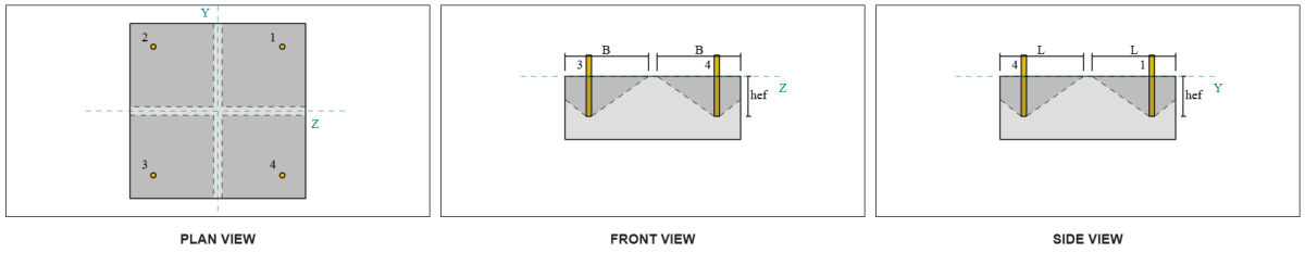
Este cálculo de ruptura de concreto se basa en la identificación de anclaje #1. La misma capacidad se aplicará a los otros anclajes debido al diseño simétrico.
Cheque #5: Calcular la capacidad de extracción de anclaje
La capacidad de extracción de un ancla se rige por la resistencia en su extremo integrado. Para anclajes enganchados, depende de su longitud de gancho.
Calculamos el Resistencia de extracción de anclaje básico factorizado por CSA A23.3:19 Eq. D.17.
\(
NORTE_{PRS} = Psi_{c,pag} 0.9 \fi (f’_c) e_h d_a r = 1 \veces 0.9 \veces 0.65 \veces (20.68 \, \texto{MPa}) \veces 60 \, \texto{mm} \veces 19.05 \, \texto{mm} \veces 1 = 13.828 \, \texto{kN}
\)
Recuerde el previamente calculado carga de tensión por ancla:
\(
NORTE_{fa} = frac{N_X}{norte_{a,t}} = frac{50 \, \texto{kN}}{4} = 12.5 \, \texto{kN}
\)
Ya que 12.5 kN < 13.828 kN, La capacidad de extracción de anclaje es suficiente.
Cheque #6: Calcule la capacidad de reventón de la cara lateral en la dirección Y
Este cálculo no es aplicable para anclajes enganchados.
Cheque #7: Calcule la capacidad de reventón de la cara lateral en la dirección Z
Este cálculo no es aplicable para anclajes enganchados.
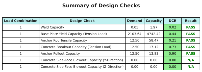
Resumen de diseño
El Software de diseño de placa base de SkyCiv puede generar automáticamente un informe de cálculo paso a paso para este ejemplo de diseño. También proporciona un resumen de los controles realizados y sus proporciones resultantes, Hacer que la información sea fácil de entender de un vistazo. A continuación se muestra una tabla de resumen de muestra, que se incluye en el informe.
Informe de muestra de SkyCiv
Vea el nivel de detalle y claridad que puede esperar de un informe de diseño de placa base SkyCiv. El informe incluye todas las comprobaciones de diseño clave., ecuaciones, y resultados presentados en un formato claro y fácil de leer. Cumple totalmente con los estándares de diseño.. Haga clic a continuación para ver un informe de muestra generado con la calculadora de placa base SkyCiv.
Comprar software de placa base
Compre la versión completa del módulo de diseño de placa base Onits Onits sin ningún otro módulo SkyCiv. Esto le da un conjunto completo de resultados para el diseño de placa base, incluyendo informes detallados y más funcionalidad.