Ejemplo de diseño de placa base utilizando como 4100:2020, AS 3600:2018, AS 5216:2021
Declaración del problema
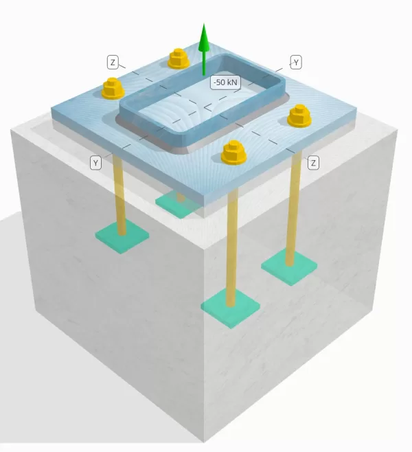
Determine si la conexión de placa de columna a base diseñada es suficiente para una carga de tensión de 50 kn..
Datos dados
Columna:
Sección de columna: 250X150X8 RHS
Área de columna: 5920 mm2
Material de columna: AS / NZS 1163 Gramo. C350
Plato base:
Dimensiones de placa base: 350 mm x 350 mm
Espesor de la placa base: 20 mm
Material de placa base: AS / NZS 1163 Gramo. C250
Lechada:
Espesor de la lechada: 20 mm
Hormigón:
Dimensiones concretas: 450 mm x 450 mm
Espesor de concreto: 400 mm
Material de hormigón: N28
Agrietado o sin crack: Agrietado
Ancla:
Diámetro de anclaje: 16 mm
Longitud de incrustación efectiva: 250.0 mm
Ancho de la placa incrustada: 70 mm
Espesor de la placa incrustada: 10 mm
Distancia de desplazamiento de anclaje desde la cara de la columna: 62.5 mm
Soldaduras:
Tipo de soldadura: Filete
Categoría de soldadura: SP
Clasificación de metal de relleno: E43xx
Aniquilar datos (de Calculadora de SkyCiv):
Modelo en la herramienta gratuita SkyCiv
Modele el diseño de la placa base anterior utilizando nuestra herramienta gratuita en línea hoy! No es necesario registrarse.
Definiciones
Ruta de carga:
Cuando una placa base está sujeta a elevación (de tensión) efectivo, Estas fuerzas se transfieren a las varillas de anclaje, que a su vez inducen momentos de flexión en la placa base. La acción de flexión se puede visualizar como flexión en voladizo ocurriendo alrededor de las bridas o la web de la sección de la columna, dependiendo de dónde estén posicionados los anclajes.
En el Software de diseño de placa base SkyCiv, solo anclajes ubicados dentro del zona de tensión de anclaje se consideran efectivos para resistir la elevación. Esta zona generalmente incluye áreas cerca de las bridas de la columna o la web.. Para columnas rectangulares, La zona de tensión de anclaje se refiere al área adyacente a las paredes de la columna. Los anclajes fuera de esta zona no contribuyen a la resistencia a la tensión y se excluyen de los cálculos de elevación.
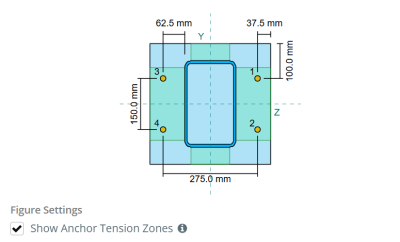
Para determinar el área efectiva de la placa base que resiste la flexión, a 45-dispersión de grado se supone desde la línea central de cada barra de anclaje hacia la cara de la columna. Esta dispersión define el longitud de soldadura efectiva y ayuda a establecer el Ancho de flexión efectivo del plato.
La suposición simplifica el análisis de la placa base al aproximar cómo la fuerza de elevación se extiende a través de la placa.
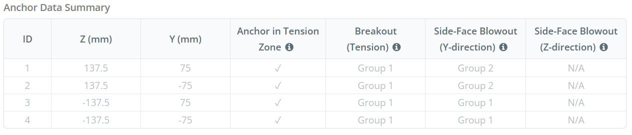
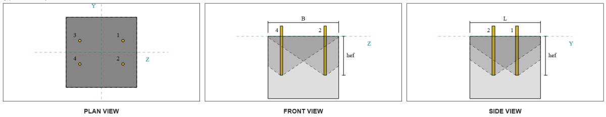
Grupos de anclaje:
El Software de diseño de placa base SkyCiv Incluye una característica intuitiva que identifica qué anclajes son parte de un grupo de anclaje para evaluar ruptura de concreto y reventón de cara lateral de concreto fallas.
Un grupo de ancla consiste en múltiples anclajes con profundidades de incrustación efectivas similares y espaciado, y están lo suficientemente cerca como para que su áreas de resistencia proyectadas superpuesto. Cuando se agrupan los anclajes, Sus capacidades se combinan para resistir la fuerza de tensión total aplicada al grupo.
Los anclajes que no cumplen con los criterios de agrupación se tratan como anclajes individuales. En este caso, Solo la fuerza de tensión sobre el ancla individual se verifica en su propio área de resistencia efectiva.
Factor de aumento de curiosidad:
El Software de diseño de placa base SkyCiv Incluye una opción para aplicar un Factor de aumento de curiosidad para dar cuenta de fuerzas de tracción adicionales en los anclajes debido a la acción indecente. Este factor aumenta la demanda de carga en los anclajes durante las verificaciones de anclaje, proporcionando una evaluación más conservadora y realista cuando corresponda. Por defecto, El factor de aumento de la curva se establece en 1.0, lo que significa que no se aplica una carga de indicación adicional a menos que el usuario especifique.
Cálculos paso a paso:
Cheque #1: Calcular la capacidad de soldadura
Empezar, Necesitamos calcular la carga por ancla y la longitud de soldadura efectiva por ancla. La longitud efectiva de la soldadura está determinada por la longitud más corta de la dispersión de 45 °, restringido por la longitud de la soldadura real y el espacio de anclaje.
Para este cálculo, Los anclajes se clasifican como cualquiera Anclas finales o anclajes intermedios. Los anclajes finales se encuentran en los extremos de una fila o columna de anclajes, mientras que los anclajes intermedios se colocan entre ellos. El método de cálculo difiere para cada uno y depende de la geometría de la columna. En este ejemplo, Hay dos anclajes a lo largo de la web, y ambos se clasifican como anclajes finales.
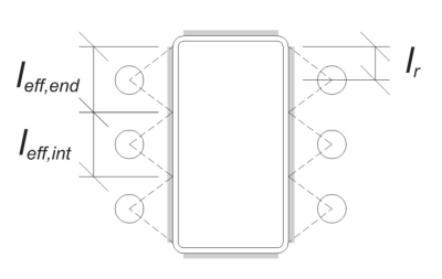
Para anclajes finales, La longitud efectiva de la soldadura está limitada por la distancia disponible desde la línea central de anclaje hasta el radio de la esquina de la columna. La dispersión de 45 ° no debe extenderse más allá de este límite.
\(
l_r = frac{D_{columna} – 2A continuación se muestra un ejemplo de algunos cálculos de placa base australianos que se usan comúnmente en el diseño de placa base{columna} – 2r_{columna} – s_y (norte_{a,\texto{lado}} – 1)}{2} = frac{250 \, \texto{mm} – 2 \veces 8 \, \texto{mm} – 2 \veces 12 \, \texto{mm} – 150 \, \texto{mm} \veces (2 – 1)}{2} = 30 \, \texto{mm}
\)
En el lado interno, La longitud efectiva está limitada por la mitad del espacio de anclaje. La longitud total de soldadura efectiva para el ancla final es la suma de las longitudes externas e internas.
\(
l_{efecto,final} = min left( hacer, 0.5 S_Y DERECHA) + \min izquierda( hacer, l_r a la derecha)
\)
\(
l_{efecto,final} = min left( 62.5 \, \texto{mm}, 0.5 \veces 150 \, \texto{mm} \verdad) + \min izquierda( 62.5 \, \texto{mm}, 30 \, \texto{mm} \verdad) = 92.5 \, \texto{mm}
\)
En este ejemplo, La longitud de soldadura efectiva final para el ancla web se toma como la longitud efectiva del ancla final.
\(
l_{efecto} = L_{efecto,final} = 92.5 \, \texto{mm}
\)
próximo, Calculemos la carga por ancla. Para un conjunto dado de cuatro (4) anclas, La carga por ancla es:
\(
T_{tu,ancla} = frac{N_X}{norte_{a,t}} = frac{50 \, \texto{kN}}{4} = 12.5 \, \texto{kN}
\)
Usando la longitud de soldadura efectiva calculada, Ahora podemos calcular la fuerza requerida por unidad de longitud que actúa sobre la soldadura.
\(
V^*_ w = frac{T_{tu,ancla}}{l_{efecto}} = frac{12.5 \, \texto{kN}}{92.5 \, \texto{mm}} = 0.13514 \, \texto{kN / mm}
\)
Ahora, usaremos AS 4100:2020 Cláusula 9.6.3.10 Para calcular la resistencia de diseño de la soldadura de filete.
\(
\Phi v_w = phi 0.6 F_{tu} E_w k_r = 0.8 \veces 0.6 \veces 430 \, \texto{MPa} \veces 5.657 \, \texto{mm} \veces 1 = 1.1676 \, \texto{kN / mm}
\)
Además de verificar la soldadura, También necesitamos verificar el Resistencia del metal base contra la fuerza de tensión aplicada para asegurarse de que no rige el modo de falla.
\(
\A continuación se muestra un ejemplo de algunos cálculos de placa base australianos que se usan comúnmente en el diseño de placa base{WBM} = phi izquierda( \min izquierda( F_{y_col} A continuación se muestra un ejemplo de algunos cálculos de placa base australianos que se usan comúnmente en el diseño de placa base{columna}, F_{y_bp} A continuación se muestra un ejemplo de algunos cálculos de placa base australianos que se usan comúnmente en el diseño de placa base{pb} \verdad) \verdad)
\)
\(
\A continuación se muestra un ejemplo de algunos cálculos de placa base australianos que se usan comúnmente en el diseño de placa base{WBM} = 0.9 \veces left( \min izquierda( 350 \, \texto{MPa} \veces 8 \, \texto{mm}, 250 \, \texto{MPa} \veces 20 \, \texto{mm} \verdad) \verdad) = 2.52 \, \texto{kN / mm}
\)
En este caso, La resistencia a la soldadura gobierna sobre la resistencia del metal base.
Ya que 0.13514 kN / mm < 1.1676 kN / mm, La capacidad de soldadura es suficiente.
Cheque #2: Calcule la capacidad de rendimiento de flexión de la placa base debido a la carga de tensión
Utilizando la Carga por ancla y la distancia de desplazamiento desde el centro del ancla hasta la cara de la columna (sirviendo como excentricidad de carga), El momento aplicado a la placa base se puede calcular utilizando un viga voladiza suposición.
\(
M^* = t_{tu,ancla} e = 12.5 \, \texto{kN} \veces 62.5 \, \texto{mm} = 781.25 \, \texto{kN} \CDOT Texto{mm}
\)
próximo, Usando el calculado longitud de soldadura efectiva Desde el cheque anterior como el ancho de flexión, podemos calcular el Calcula la capacidad de carga de la placa base usando AISC 360-22, Ecuación 2-1:
\(
\Phi m_s = phi z_{efecto} F_{y_bp} = 0.9 \veces 9250 \, \texto{mm}^3 veces 250 \, \texto{MPa} = 2081.2 \, \texto{kN} \CDOT Texto{mm}
\)
Dónde,
\(
Z_{efecto} = frac{l_{efecto} (A continuación se muestra un ejemplo de algunos cálculos de placa base australianos que se usan comúnmente en el diseño de placa base{pb})^ 2}{4} = frac{92.5 \, \texto{mm} \veces (20 \, \texto{mm})^ 2}{4} = 9250 \, \texto{mm}^ 3
\)
Ya que 781.25 KN-MM < 2081.2 KN-MM, La capacidad de rendimiento de flexión de la placa base es suficiente.
Cheque #3: Calcular la capacidad de tracción de la barra de anclaje
Para evaluar el Capacidad de tracción de la barra de anclaje, Nos referimos a AS 5216:2021 Cláusula 6.2.2 y AS 4100:2020 Cláusula 9.2.2.2.
primero, Determinamos el área de tensión de tracción de la porción roscada de la barra, siguiente AS 4100:2020 Cláusula 7.2 y Como una cláusula 1275–1985 1.7.
\(
A_n = frac{\pi}{4} \izquierda( \frac{D_A}{\texto{mm}} – 0.9382 P Derecha)^ 2 \, \texto{mm}^2 = frac{\pi}{4} \veces left( \frac{16 \, \texto{mm}}{1 \, \texto{mm}} – 0.9382 \veces 2 \verdad)^2 veces 1 \, \texto{mm}^2 = 156.67 \, \texto{mm}^ 2
\)
Utilizando AS 4100:2020 Cláusula 9.2.2, calculamos el capacidad de tensión nominal del perno basado en el área de tensión de tracción y la resistencia del material.
\(
NORTE_{tf} = A_n f_{u _anc} = 156.67 \, \texto{mm}^2 veces 800 \, \texto{MPa} = 125.33 \, \texto{kN}
\)
Luego aplicamos el factor de resistencia apropiado para obtener el Capacidad de anclaje de diseño en tensión.
\(
\phi N_{Rk,s} = Phi n_{tf} = 0.8 \veces 125.33 \, \texto{kN} = 100.27 \, \texto{kN}
\)
Recuerde el previamente calculado carga de tensión por ancla, y aplicar el Factor de aumento de curiosidad Si se especifica.
\(
N^* = p izquierda( \frac{N_X}{norte_{a,t}} \verdad) = 1 \veces left( \frac{50 \, \texto{kN}}{4} \verdad) = 12.5 \, \texto{kN}
\)
Ya que 12.5 kN < 100.27 kN, la La capacidad de tracción de la barra de anclaje es suficiente.
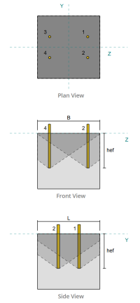
Cheque #4: Calcule la capacidad de ruptura de concreto en tensión
Antes de calcular la capacidad de ruptura, Primero debemos determinar si el miembro califica como un miembro estrecho. De acuerdo a AS 5216:2021 Cláusula 6.2.3.8, El miembro cumple con los criterios para un miembro estrecho. Por lo tanto, a modificado Longitud de incrustación efectiva debe usarse en los cálculos de capacidad de ruptura. Este ajuste también afecta el espaciado característico y distancia de borde característico, que debe modificarse en consecuencia.
Basado en los criterios de miembros estrechos, la valores modificados Para el grupo de anclajes son los siguientes:
- Longitud de incrustación efectiva modificada, \(H’_{ef} = 100 \, \texto{mm}\)
- espaciado característico modificado, \(s'_{cr} = 300 \, \texto{mm}\)
- distancia de borde característico modificado, \(do'_{cr} = 150 \, \texto{mm}\)
Utilizando AS 5216: 2021 Cláusula 6.2.3.3, calculamos el Referencia Área de cono de concreto proyectado para un solo ancla.
\(
A0_{c,norte} = left( s'_{cr,G1} \verdad)^2 = izquierda( 300 \, \texto{mm} \verdad)^2 = 90000 \, \texto{mm}^ 2
\)
De igual forma, calculamos el Área real de cono de concreto proyectado del grupo de ancla.
\(
UNA_{Carolina del Norte} = L_{Carolina del Norte} SI_{Carolina del Norte} = 450 \, \texto{mm} \veces 450 \, \texto{mm} = 202500 \, \texto{mm}^ 2
\)
Dónde,
\(
L_{Carolina del Norte} = min left( C_{izquierda,G1}, do'_{cr,G1} + r_{incrustar _plate} \verdad) + \min izquierda( s_{suma,z,G1}, s'_{cr,G1} \CDOT Izquierda( norte_{z,G1} – 1 \verdad) \verdad) + \min izquierda( C_{verdad,G1}, do'_{cr,G1} + r_{incrustar _plate} \verdad)
\)
\(
L_{Carolina del Norte} = min left( 87.5 \, \texto{mm}, 150 \, \texto{mm} + 18 \, \texto{mm} \verdad) + \min izquierda( 275 \, \texto{mm}, 300 \, \texto{mm} \cdot (2 – 1) \verdad) + \min izquierda( 87.5 \, \texto{mm}, 150 \, \texto{mm} + 18 \, \texto{mm} \verdad)
\)
\(
L_{Carolina del Norte} = 450 \, \texto{mm}
\)
\(
SI_{Carolina del Norte} = min left( C_{superior,G1}, do'_{cr,G1} + r_{incrustar _plate} \verdad) + \min izquierda( s_{suma,y,G1}, s'_{cr,G1} \CDOT Izquierda( norte_{y,G1} – 1 \verdad) \verdad) + \min izquierda( C_{inferior,G1}, do'_{cr,G1} + r_{incrustar _plate} \verdad)
\)
\(
SI_{Carolina del Norte} = min izquierda( 150 \, \texto{mm}, 150 \, \texto{mm} + 18 \, \texto{mm} \verdad) + \min izquierda( 150 \, \texto{mm}, 300 \, \texto{mm} \cdot (2 – 1) \verdad) + \min izquierda( 150 \, \texto{mm}, 150 \, \texto{mm} + 18 \, \texto{mm} \verdad)
\)
\(
SI_{Carolina del Norte} = 450 \, \texto{mm}
\)
El Radio efectivo de la placa incrustada se utiliza para proporcionar una capacidad adicional para la ruptura de concreto. Para determinar esto, Agregue el grosor de la placa incrustada a la mitad del diámetro de anclaje.
próximo, Evaluamos el fuerza característica de un solo ancla usando AS 5216:2021 Eq. 6.2.3.2
\(
N0_{Rk,c} = k_1 sqrt{\frac{f’_c}{\texto{MPa}}} \izquierda( \frac{H’_{ef,G1}}{\texto{mm}} \verdad)^{1.5} \, \texto{norte}
\)
\(
N0_{Rk,c} = 8.9 \veces sqrt{\frac{28 \, \texto{MPa}}{1 \, \texto{MPa}}} \veces left( \frac{100 \, \texto{mm}}{1 \, \texto{mm}} \verdad)^{1.5} \veces 0.001 \, \texto{kN} = 47.094 \, \texto{kN}
\)
Dónde,
- \(Suma de fuerzas de tensión de anclajes con área de cono de ruptura de concreto común{1} = 8.9\) para anclajes empotrados
Ahora, Evaluamos los efectos de la geometría calculando lo necesario parámetros para la resistencia de la ruptura.
La distancia de borde más corta del grupo de anclaje se determina como:
\(
C_{min,norte} = min left( C_{izquierda,G1}, C_{verdad,G1}, C_{superior,G1}, C_{inferior,G1} \verdad) = min left( 87.5 \, \texto{mm}, 87.5 \, \texto{mm}, 150 \, \texto{mm}, 150 \, \texto{mm} \verdad) = 87.5 \, \texto{mm}
\)
De acuerdo a AS 5216:2021 Eq. 6.2.3.4, El valor para el parámetro que representa la distribución del estrés en el concreto es:
\(
\Psi_{s,norte} = min left( 0.7 + 0.3 \izquierda( \frac{C_{min,norte}}{do'_{cr,G1}} \verdad), 1.0 \verdad) = min left( 0.7 + 0.3 \veces left( \frac{87.5 \, \texto{mm}}{150 \, \texto{mm}} \verdad), 1 \verdad) = 0.875
\)
El efecto de espalda de concha se contabiliza el uso AS 5216:2021 Ecuación 6.2.3.5, donación:
\(
\Psi_{re,norte} = min left( 0.5 + \frac{H’_{ef,G1}}{\texto{mm} \cdot 200}, 1.0 \verdad) = min left( 0.5 + \frac{100 \, \texto{mm}}{1 \, \texto{mm} \cdot 200}, 1 \verdad) = 1
\)
Adicionalmente, ambos factor de excentricidad y el Factor de influencia de compresión son tomados como:
\(
\Psi_{CE,norte} = 1
\)
\(
\Psi_{M,norte} = 1
\)
Luego combinamos todos estos factores y aplicamos AS 5216:2021 Ecuación 6.2.3.1 para evaluar el Diseño de resistencia de ruptura de cono de concreto para el grupo de anclaje:
\(
\phi N_{Rk,c} = phi_{Mc} N0_{Rk,c} \izquierda( \frac{UNA_{Carolina del Norte}}{A0_{c,norte}} \verdad) \Psi_{s,norte} \Psi_{re,norte} \Psi_{CE,norte} \Psi_{M,norte}
\)
\(
\phi N_{Rk,c} = 0.6667 \veces 47.094 \, \texto{kN} \veces left( \frac{202500 \, \texto{mm}^ 2}{90000 \, \texto{mm}^ 2} \verdad) \veces 0.875 \veces 1 \veces 1 \veces 1 = 61.814 \, \texto{kN}
\)
El Total de carga de tensión aplicada en el grupo de anclaje se calcula multiplicando la carga de tensión por ancla por el número de anclajes, con el factor de aumento de lo que se aplica según sea necesario:
\(
N^* = p izquierda( \frac{N_X}{norte_{a,t}} \verdad) norte_{a,G1} = 1 \veces left( \frac{50 \, \texto{kN}}{4} \verdad) \veces 4 = 50 \, \texto{kN}
\)
Ya que 50 kN < 61.814 kN La capacidad de ruptura de concreto es suficiente.
Cheque #5: Calcular la capacidad de extracción de anclaje
El capacidad de extracción de un ancla se rige por la resistencia en su extremo integrado. primero, Calculamos la dimensión máxima del cabezal de anclaje efectiva para la resistencia de extracción, según por AS 5216:2021 Cláusula 6.3.4.
\(
D_{h,\texto{max}} = min left( B_{incrustar _plate}, 6 \izquierda( A continuación se muestra un ejemplo de algunos cálculos de placa base australianos que se usan comúnmente en el diseño de placa base{incrustar _plate} \verdad) + D_A DERECHA) = min left( 70 \, \texto{mm}, 6 \veces (10 \, \texto{mm}) + 16 \, \texto{mm} \verdad) = 70 \, \texto{mm}
\)
próximo, Calculamos el área de cojinete neto de la placa incrustada rectangular utilizando:
\(
A_h = izquierda( D_{h,\texto{max}}^2 Derecha) – UNA_{vara} = left( (70 \, \texto{mm})^2 Derecha) – 201.06 \, \texto{mm}^2 = 4698.9 \, \texto{mm}^ 2
\)
Dónde,
\(
UNA_{vara} = frac{\pi}{4} (D_A)^2 = frac{\pi}{4} \veces (16 \, \texto{mm})^2 = 201.06 \, \texto{mm}^ 2
\)
Luego calculamos el Diseño de fuerza de extracción de anclaje básico usando AS 5216:2021 Cláusula 6.3.4:
\(
NORTE_{Rk,pag} = phi_{Mc} k_2 a_h izquierda( F’_C Derecha) = 0.6667 \veces 7.5 \veces 4698.9 \, \texto{mm}^2 veces (28 \, \texto{MPa}) = 657.88 \, \texto{kN}
\)
Recuerde el previamente calculado carga de tensión por ancla:
\(
N^* = p izquierda( \frac{N_X}{norte_{a,t}} \verdad) = 1 \veces left( \frac{50 \, \texto{kN}}{4} \verdad) = 12.5 \, \texto{kN}
\)
Ya que 12.5 kN < 657.88 kN, La capacidad de extracción de anclaje es suficiente.
Cheque #6: Calcule la capacidad de reventón de la cara lateral en la dirección Y
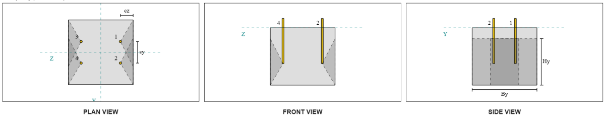
Consideremos el grupo de anclaje de reventón de cara lateral 1 Para el cálculo de la capacidad. Refiriéndose al resumen de datos de anclaje, IDS de anclaje 3 y 4 son parte del grupo sfy 1.
Comenzamos calculando la distancia de borde a la fallas.
\(
C_{z,\texto{min}} = min left( C_{\texto{izquierda},G1}, C_{\texto{verdad},G1} \verdad) = min left( 87.5 \, \texto{mm}, 362.5 \, \texto{mm} \verdad) = 87.5 \, \texto{mm}
\)
próximo, Determinamos la distancia de borde al borde ortogonal.
\(
C_{y,\texto{min}} = min left( C_{\texto{superior},G1}, C_{\texto{inferior},G1} \verdad) = min left( 150 \, \texto{mm}, 150 \, \texto{mm} \verdad) = 150 \, \texto{mm}
\)
Utilizando AS 5216:2021 Cláusula 6.2.7.3, Calculemos el Área proyectada de referencia de un solo sujetador.
\(
A0_{c,Nótese bien} = left( 4 C_{z,\texto{min}} \verdad)^2 = izquierda( 4 \veces 87.5 \, \texto{mm} \verdad)^2 = 122500 \, \texto{mm}^ 2
\)
Dado que estamos revisando la capacidad del grupo de ancla, Vamos a conseguir el Área proyectada real del grupo de anclaje usando AS 5216:2021 Cláusula 6.2.7.2.
\(
UNA_{Carolina del Norte} = B_{c,Nótese bien} se requiere realizar una sumatoria de momentos con respecto al punto mencionado de todas las cargas verticales{c,Nótese bien} = 450 \, \texto{mm} \veces 325 \, \texto{mm} = 146250 \, \texto{mm}^ 2
\)
Dónde,
\(
SI_{c,Nótese bien} = min left( 2 C_{z,\texto{min}}, C_{\texto{superior},G1} \verdad) + s_{\texto{suma},y,G1} + \min izquierda( 2 C_{z,\texto{min}}, C_{\texto{inferior},G1} \verdad)
\)
\(
SI_{c,Nótese bien} = min left( 2 \veces 87.5 \, \texto{mm}, 150 \, \texto{mm} \verdad) + 150 \, \texto{mm} + \min izquierda( 2 \veces 87.5 \, \texto{mm}, 150 \, \texto{mm} \verdad) = 450 \, \texto{mm}
\)
\(
se requiere realizar una sumatoria de momentos con respecto al punto mencionado de todas las cargas verticales{c,Nótese bien} = 2 C_{z,\texto{min}} + \izquierda( \min izquierda( A continuación se muestra un ejemplo de algunos cálculos de placa base australianos que se usan comúnmente en el diseño de placa base{\texto{sobre}} – h_{\texto{ef}}, 2 C_{z,\texto{min}} \verdad) \verdad)
\)
\(
se requiere realizar una sumatoria de momentos con respecto al punto mencionado de todas las cargas verticales{c,Nótese bien} = 2 \veces 87.5 \, \texto{mm} + \izquierda( \min izquierda( 400 \, \texto{mm} – 250 \, \texto{mm}, 2 \veces 87.5 \, \texto{mm} \verdad) \verdad) = 325 \, \texto{mm}
\)
En calcular el resistencia a la explosión de concreto característico de un ancla individual, usaremos AS 5216:2021 Cláusula 6.2.7.2.
\(
N0_{Rk,cb} = k_5 izquierda( \frac{C_{z,\texto{min}}}{\texto{mm}} \verdad) \sqrt{\frac{A_h}{\texto{mm}^ 2}} \sqrt{\frac{f’_c}{\texto{MPa}}} \, norte
\)
\(
N0_{Rk,cb} = 8.7 \veces left( \frac{87.5 \, \texto{mm}}{1 \, \texto{mm}} \verdad) \veces sqrt{\frac{4698.9 \, \texto{mm}^ 2}{1 \, \texto{mm}^ 2}} \veces sqrt{\frac{28 \, \texto{MPa}}{1 \, \texto{MPa}}} \veces 0.001 \, \texto{kN}
\)
\(
N0_{Rk,cb} = 276.13 \, \texto{kN}
\)
Dónde,
- \(Suma de fuerzas de tensión de anclajes con área de cono de ruptura de concreto común{5} = 8.7\) para hormigón fisurado
- \(Suma de fuerzas de tensión de anclajes con área de cono de ruptura de concreto común{5} = 12.2\) para hormigón no agrietado
Luego, Obtendremos el Parámetros de reventón de cara lateral.
El parámetro que explica la perturbación de la distribución de tensiones en el concreto se puede calcular a partir de AS 5216:2021 Cláusula 6.2.7.4.
\(
\Psi_{s,Nótese bien} = min left( 0.7 + 0.3 \izquierda( \frac{C_{y,\texto{min}}}{2 C_{z,\texto{min}}} \verdad), 1.0 \verdad)
\)
\(
\Psi_{s,Nótese bien} = min left( 0.7 + 0.3 \veces left( \frac{150 \, \texto{mm}}{2 \veces 87.5 \, \texto{mm}} \verdad), 1 \verdad) = 0.95714
\)
La ecuación de AS 5216:2021 Cláusula 6.2.7.5 Luego se usa para obtener el parámetro que contabiliza el efecto grupal.
\(
\Psi_{gramo,Nótese bien} = max left( \sqrt{norte_{y,G1}} + \izquierda( 1 – \sqrt{norte_{y,G1}} \verdad) \izquierda( \frac{\min izquierda( s_{y,G1}, 4 C_{z,\texto{min}} \verdad)}{4 C_{z,\texto{min}}} \verdad), 1.0 \verdad)
\)
\(
\Psi_{gramo,Nótese bien} = max left( \sqrt{2} + \izquierda( 1 – \sqrt{2} \verdad) \veces left( \frac{\min izquierda( 150 \, \texto{mm}, 4 \veces 87.5 \, \texto{mm} \verdad)}{4 \veces 87.5 \, \texto{mm}} \verdad), 1 \verdad)
\)
\(
\Psi_{gramo,Nótese bien} = 1.2367
\)
Finalmente, en referencia a AS 5216:2021 Eq. 6.2.7 Para varillas de anclaje de cabeza, la Diseño de resistencia a la reventilla de concreto es:
\(
\phi N_{Rk,cb} = phi_m n0_{Rk,cb} \izquierda( \frac{UNA_{Carolina del Norte}}{A0_{c,Nótese bien}} \verdad) \Psi_{s,Nótese bien} \Psi_{gramo,Nótese bien} \Psi_{CE,norte}
\)
\(
\phi N_{Rk,cb} = 0.6667 \veces 276.13 \, \texto{kN} \veces left( \frac{146250 \, \texto{mm}^ 2}{122500 \, \texto{mm}^ 2} \verdad) \veces 0.95714 \veces 1.2367 \veces 1 = 260.16 \, \texto{kN}
\)
Para este grupo de anclaje, Solo dos (2) Los anclajes pertenecen al grupo. Por lo tanto, la Fuerza de tensión de diseño para el grupo de anclaje es:
\(
N^* = p izquierda( \frac{N_X}{norte_{a,t}} \verdad) norte_{y,G1}
\)
\(
N^* = 1 \veces left( \frac{50 \, \texto{kN}}{4} \verdad) \veces 2 = 25 \, \texto{kN}
\)
Ya que 25 kN < 260.16 kN, El reventón de la cara lateral de concreto a lo largo de la dirección es suficiente.
Grupo de anclaje de reventón de cara lateral 2 También se puede usar y producirá el mismo resultado, Dado que el diseño es simétrico.
Cheque #7: Calcule la capacidad de reventón de la cara lateral en la dirección Z
Este cálculo no es aplicable para la falla a lo largo de la dirección z, A medida que la distancia del borde a los lados excede la mitad de la longitud de incrustación efectiva.
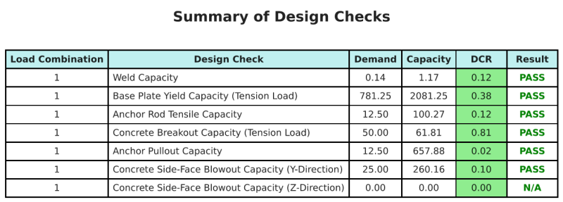
Resumen de diseño
El Software de diseño de placa base de SkyCiv puede generar automáticamente un informe de cálculo paso a paso para este ejemplo de diseño. También proporciona un resumen de los controles realizados y sus proporciones resultantes, Hacer que la información sea fácil de entender de un vistazo. A continuación se muestra una tabla de resumen de muestra, que se incluye en el informe.
Informe de muestra de SkyCiv
Vea el nivel de detalle y claridad que puede esperar de un informe de diseño de placa base SkyCiv. El informe incluye todas las comprobaciones de diseño clave., ecuaciones, y resultados presentados en un formato claro y fácil de leer. Cumple totalmente con los estándares de diseño.. Haga clic a continuación para ver un informe de muestra generado con la calculadora de placa base SkyCiv.
Comprar software de placa base
Compre la versión completa del módulo de diseño de la placa base por sí solo sin ningún otro módulo SkyCiv. Esto le da un conjunto completo de resultados para el diseño de placa base, incluyendo informes detallados y más funcionalidad.