Ejemplo de diseño de placa base usando AISC 360-22 y ACI 318-19
Declaración del problema
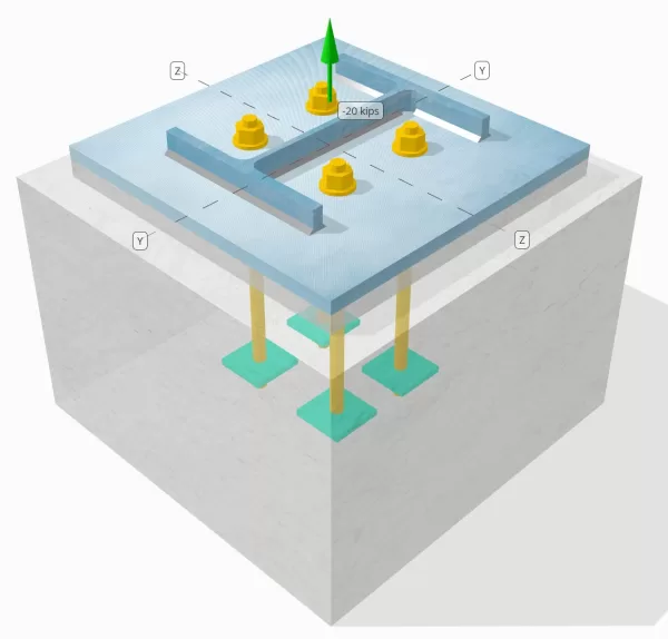
Determine si la conexión de placa de columna a base diseñada es suficiente para una carga de tensión de 20 kips.
Datos dados
Columna:
Sección de columna: W12x53
Área de columna: 15.6 in2
Material de columna: A992
Plato base:
Dimensiones de placa base: 18 en x 18 in
Espesor de la placa base: 3/4 in
Material de placa base: A36
Lechada:
Espesor de la lechada: 1 in
Hormigón:
Dimensiones concretas: 22 en x 22 in
Espesor de concreto: 15 in
Material de hormigón: 4000 psi
Agrietado o sin crack: Agrietado
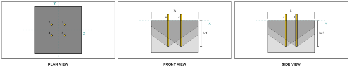
Ancla:
Diámetro de anclaje: 3/4 in
Longitud de incrustación efectiva: 12 in
Ancho de la placa incrustada: 3 in
Espesor de la placa incrustada: 1/4 in
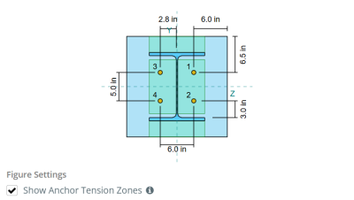
Distancia de desplazamiento de anclaje desde la cara de la red de columna: 2.8275 in
Soldaduras:
Tamaño de soldadura: 1/4 in
Clasificación de metal de relleno: E70XX
Aniquilar datos (de Calculadora de SkyCiv):
Modelo en la herramienta gratuita SkyCiv
Modele el diseño de la placa base anterior utilizando nuestra herramienta gratuita en línea hoy! No es necesario registrarse.
Definiciones
Ruta de carga:
Cuando una placa base está sujeta a elevación (de tensión) efectivo, Estas fuerzas se transfieren a las varillas de anclaje, que a su vez inducen momentos de flexión en la placa base. La acción de flexión se puede visualizar como flexión en voladizo ocurriendo alrededor de las bridas o la web de la sección de la columna, dependiendo de dónde estén posicionados los anclajes.
En el Software de diseño de placa base SkyCiv, solo anclajes ubicados dentro del zona de tensión de anclaje se consideran efectivos para resistir la elevación. Esta zona generalmente incluye áreas cerca de las bridas de la columna o la web.. Los anclajes fuera de esta zona no contribuyen a la resistencia a la tensión y se excluyen de los cálculos de elevación.
Para determinar el área efectiva de la placa base que resiste la flexión, a 45-dispersión de grado se supone desde la línea central de cada barra de anclaje hacia la cara de la columna. Esta dispersión define el longitud de soldadura efectiva y ayuda a establecer el Ancho de flexión efectivo del plato.
La suposición simplifica el análisis de la placa base al aproximar cómo la fuerza de elevación se extiende a través de la placa.
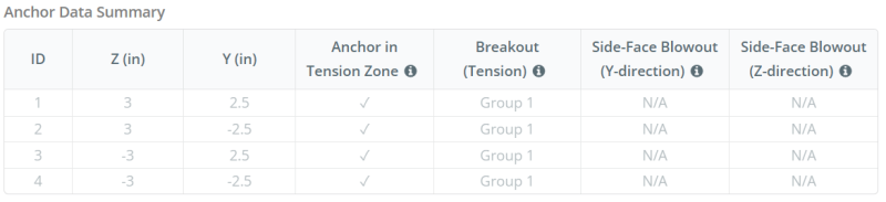
Grupos de anclaje:
El Software de diseño de placa base SkyCiv Incluye una característica intuitiva que identifica qué anclajes son parte de un grupo de anclaje para evaluar ruptura de concreto y sid de concretoreventón de la cara electrónica fallas.
Un grupo de ancla consiste en múltiples anclajes con profundidades de incrustación efectivas similares y espaciado, y están lo suficientemente cerca como para que su áreas de resistencia proyectadas superpuesto. Cuando se agrupan los anclajes, Sus capacidades se combinan para resistir la fuerza de tensión total aplicada al grupo.
Los anclajes que no cumplen con los criterios de agrupación se tratan como anclajes individuales. En este caso, Solo la fuerza de tensión sobre el ancla individual se verifica en su propio área de resistencia efectiva.
Cálculos paso a paso
Cheque #1: Calcular la capacidad de soldadura
Empezar, Necesitamos calcular la carga por ancla y la longitud de soldadura efectiva por ancla. La longitud efectiva de la soldadura está determinada por la longitud más corta del 45° dispersión, restringido por la longitud de la soldadura real y el espacio de anclaje.
Para este cálculo, Los anclajes se clasifican como cualquiera Anclas finales o anclajes intermedios. Los anclajes finales se encuentran en los extremos de una fila o columna de anclajes, mientras que los anclajes intermedios se colocan entre ellos. El método de cálculo difiere para cada uno y depende de la geometría de la columna. En este ejemplo, Hay dos anclajes a lo largo de la web, y ambos se clasifican como anclajes finales.
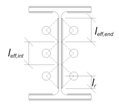
Para anclajes finales, La longitud de soldadura efectiva está limitada por la distancia disponible desde la línea central de anclaje hasta el filete de columna. La dispersión de 45 ° no debe extenderse más allá de este límite.
\(
l_r = frac{D_{columna} – 2T_F – 2r_{columna} – s_y(norte_{a,lado} – 1)}{2} = frac{12.1 \, \texto{in} – 2 \veces 0.575 \, \texto{in} – 2 \veces 0.605 \, \texto{in} – 5 \, \texto{in} \veces (2 – 1)}{2} = 2.37 \, \texto{in}
\)
En el lado interno, La longitud efectiva está limitada por la mitad del espacio de anclaje. La longitud total de soldadura efectiva para el ancla final es la suma de las longitudes externas e internas.
\(
l_{efecto,final} = min(hacer, 0.5s_y) + \min(hacer, L_R)
\)
\(
l_{efecto,final} = min(2.8275 \, \texto{in}, 0.5 \veces 5 \, \texto{in}) + \min(2.8275 \, \texto{in}, 2.37 \, \texto{in}) = 4.87 \, \texto{in}
\)
En este ejemplo, la longitud de soldadura efectiva final para el ancla web se toma como la longitud efectiva del ancla final.
\(
l_{efecto} = L_{efecto,final} = 4.87 \, \texto{in}
\)
próximo, Calculemos el Carga por ancla. Para un conjunto dado de cuatro (4) anclas, La carga por ancla es:
\(
T_{tu,ancla} = frac{N_X}{norte_{a,t}} = frac{20 \, \texto{kip}}{4} = 5 \, \texto{kip}
\)
Usando la longitud de soldadura efectiva calculada, Ahora podemos determinar el fuerza requerida por unidad de longitud en la soldadura.
\(
r_u = frac{T_{tu,ancla}}{l_{efecto}} = frac{5 \, \texto{kip}}{4.87 \, \texto{in}} = 1.0267 \, \texto{kip/in}
\)
Ahora, usaremos AISC 360-22, Capítulo J2.4 Para calcular la resistencia de diseño de la soldadura de filete.
Dado que la carga aplicada es tensión puramente axial, el ángulo \(\theta) se toma como 90 °, y el coeficiente de resistencia direccional KDS se calcula de acuerdo con AISC 360-22 Eq. J2-5.
\(
Suma de fuerzas de tensión de anclajes con área de cono de ruptura de concreto común{ds} = 1.0 + 0.5(\sin(\theta))^{1.5} = 1 + 0.5 \veces (\sin(1.5708))^{1.5} = 1.5
\)
Finalmente, aplicaremos AISC 360-22 Eq. J2-4 para determinar el resistencia de diseño de la soldadura de filete por unidad de longitud.
\(
\Phi r_n = phi 0.6 F_{Exx} MI_{w,web} Suma de fuerzas de tensión de anclajes con área de cono de ruptura de concreto común{ds} = 0.75 \veces 0.6 \veces 70 \, \texto{KSI} \veces 0.177 \, \texto{in} \veces 1.5 = 8.3633 \, \texto{kip/in}
\)
Ya que 1.0267 KPI < 8.3633 KPI, La capacidad de soldadura es suficiente.
Cheque #2: Calcule la capacidad de rendimiento de flexión de la placa base debido a la carga de tensión
Usando tSe carga por ancla y la ODistancia de ffset desde el centro del ancla a la cara de la columna (sirviendo como excentricidad de carga), El momento aplicado a la placa base se puede calcular utilizando un viga voladiza suposición.
\(
M_u = t_{tu,\texto{ancla}} e = 5 \, \texto{kip} \veces 2.8275 \, \texto{in} = 14.137 \, \texto{kip} \CDOT Texto{in}
\)
próximo, Usando la calculaciónD Longitud efectiva de soldaduraM la verificación anterior como el ancho de flexión, podemos calcular el Calcula la capacidad de carga de la placa base usando AISC 360-22, Ecuación 2-1:
\(
\non -m_n = phi f_{y,\texto{pb}} Z_{\texto{efecto}} = 0.9 \veces 36 \, \texto{KSI} \veces 0.68484 \, \texto{in}^3 = 22.189 \, \texto{kip} \CDOT Texto{in}
\)
Dónde,
\(
Z_{\texto{efecto}} = frac{l_{\texto{efecto}} (A continuación se muestra un ejemplo de algunos cálculos de placa base australianos que se usan comúnmente en el diseño de placa base{\texto{pb}})^ 2}{4} = frac{4.87 \, \texto{in} \veces (0.75 \, \texto{in})^ 2}{4} = 0.68484 \, \texto{in}^ 3
\)
Ya que 14.137 pollo en < 22.189 pollo en, La capacidad de rendimiento de flexión de la placa base es suficiente.
Cheque #3: Calcular la capacidad de tracción de la barra de anclaje
Para evaluar la capacidad de tracción de la barra de anclaje, usaremos ACI 318-19 Ecuación 17.6.1.2.
primero, Determinamos el resistencia a la tracción especificada del ancla de acero. Este es el valor más bajo permitido por ACI 318-19 Cláusula 17.6.1.2, con referencia a propiedades del material en AISC 360-22 Tabla J3.2.
\(
F_{\texto{uta}} = min left( 0.75 F_{tu,\texto{Congreso Nacional Africano}}, 1.9 F_{y,\texto{Congreso Nacional Africano}}, 125 \verdad) = min left( 0.75 \veces 120 \, \texto{KSI}, 1.9 \veces 92 \, \texto{KSI}, 125.00 \, \texto{KSI} \verdad) = 90 \, \texto{KSI}
\)
próximo, calculamos el Área transversal efectiva de la barra de ancla. Esto se basa en ACI 318-19 Cláusula de comentarios R17.6.1.2, que explica la geometría de hilos. El número de hilos por pulgada se toma de ASME B1.1-2019 Tabla 1.
\(
UNA_{se,norte} = frac{\pi}{4} \izquierda( D_A – \frac{0.9743}{Nuevo Testamento} \verdad)^2 = frac{\pi}{4} \veces left( 0.75 \, \texto{in} – \frac{0.9743}{10 \, \texto{in}^{-1}} \verdad)^2 = 0.33446 \, \texto{in}^ 2
\)
Con estos valores, Solicitamos ACI 318-19 Ecuación 17.6.1.2 para calcular el Diseño de resistencia a la tracción de la barra de ancla.
\(
\phi N_{a} = phi A_{se,norte} F_{\texto{uta}} = 0.75 \veces 0.33446 \, \texto{in}^2 veces 90 \, \texto{KSI} = 22.576 \, \texto{kip}
\)
Recuerde el previamente calculado carga de tensión por ancla:
\(
NORTE_{hacer} = frac{N_X}{norte_{a,t}} = frac{20 \, \texto{kip}}{4} = 5 \, \texto{kip}
\)
Ya que 5 kip < 22.576 kip, La capacidad de tracción de la barra de anclaje es suficiente.
Cheque #4: Calcule la capacidad de ruptura de concreto en tensión
Antes de calcular la capacidad de ruptura, Primero debemos determinar si el miembro califica como un miembro estrecho. De acuerdo a ACI 318-19 Cláusula 17.6.2.1.2, El miembro cumple con los criterios para un miembro estrecho. Por lo tanto, Se debe utilizar una longitud de incrustación efectiva modificada en los cálculos.
Se determina que el Longitud de incrustación efectiva modificada, H’Ef, del grupo de ancla es:
\(
H’_{\texto{ef}} = 5.667 \, \texto{in}
\)
Utilizando ACI 318-19 Cláusula 17.6.2, calculamos el Área máxima de cono de concreto proyectado para un solo ancla, Basado en la longitud de incrustación efectiva modificada.
\(
UNA_{NORTE_{co}} = 9 \izquierda( H’_{ef,G1} \verdad)^2 = 9 \veces left( 5.6667 \, \texto{in} \verdad)^2 = 289 \, \texto{in}^ 2
\)
De igual forma, Utilizamos la longitud de incrustación efectiva modificada para calcular el Área real de cono de concreto proyectado del grupo de ancla.
\(
UNA_{Carolina del Norte} = min left( norte_{a,G1} UNA_{NORTE_{co}}, L_{Carolina del Norte} SI_{Carolina del Norte} \verdad) = min left( 4 \veces 289 \, \texto{in}^ 2, 22 \, \texto{in} \veces 22 \, \texto{in} \verdad) = 484 \, \texto{in}^ 2
\)
Dónde,
\(
L_{Carolina del Norte} = min left( C_{\texto{izquierda},G1}, 1.5 H’_{\texto{ef},G1} \verdad)
+ \izquierda( \min izquierda( s_{\texto{suma},z,G1}, 3 H’_{\texto{ef},G1} \izquierda( norte_{z,G1} – 1 \verdad) \verdad) \verdad)
+ \min izquierda( C_{\texto{verdad},G1}, 1.5 H’_{\texto{ef},G1} \verdad)
\)
\(
L_{Carolina del Norte} = min left( 8 \, \texto{in}, 1.5 \veces 5.6667 \, \texto{in} \verdad)
+ \izquierda( \min izquierda( 6 \, \texto{in}, 3 \veces 5.6667 \, \texto{in} \veces left( 2 – 1 \verdad) \verdad) \verdad)
+ \min izquierda( 8 \, \texto{in}, 1.5 \veces 5.6667 \, \texto{in} \verdad)
\)
\(
L_{Carolina del Norte} = 22 \, \texto{in}
\)
\(
SI_{Carolina del Norte} = min left( C_{\texto{superior},G1}, 1.5 H’_{\texto{ef},G1} \verdad)
+ \izquierda( \min izquierda( s_{\texto{suma},y,G1}, 3 H’_{\texto{ef},G1} \izquierda( norte_{y,G1} – 1 \verdad) \verdad) \verdad)
+ \min izquierda( C_{\texto{inferior},G1}, 1.5 H’_{\texto{ef},G1} \verdad)
\)
\(
SI_{Carolina del Norte} = min left( 8.5 \, \texto{in}, 1.5 \veces 5.6667 \, \texto{in} \verdad)
+ \izquierda( \min izquierda( 5 \, \texto{in}, 3 \veces 5.6667 \, \texto{in} \veces left( 2 – 1 \verdad) \verdad) \verdad)
+ \min izquierda( 8.5 \, \texto{in}, 1.5 \veces 5.6667 \, \texto{in} \verdad)
\)
\(
SI_{Carolina del Norte} = 22 \, \texto{in}
\)
próximo, Evaluamos el Fuerza de ruptura de concreto básico de un solo ancla usando ACI 318-19 Cláusula 17.6.2.2.1
\(
N_b = k_c lambda_a sqrt{\frac{f’_c}{\texto{psi}}} \izquierda( \frac{H’_{\texto{ef},G1}}{\texto{in}} \verdad)^{1.5} \, \texto{lbf}
\)
\(
N_b = 24 \veces 1 \veces sqrt{\frac{4 \, \texto{KSI}}{0.001 \, \texto{KSI}}} \veces left( \frac{5.6667 \, \texto{in}}{1 \, \texto{in}} \verdad)^{1.5} \veces 0.001 \, \texto{kip} = 20.475 \, \texto{kip}
\)
Dónde,
- \(Suma de fuerzas de tensión de anclajes con área de cono de ruptura de concreto común{c} = 24\) para anclajes empotrados
- \(\lambda = 1.0 \) para concreto de peso normal
Ahora, Evaluamos los efectos de la geometría calculando el Factor de efecto de borde y el factor de excentricidad.
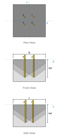
La distancia de borde más corta del grupo de anclaje se determina como:
\(
C_{a,\texto{min}} = min left( C_{\texto{izquierda},G1}, C_{\texto{verdad},G1}, C_{\texto{superior},G1}, C_{\texto{inferior},G1} \verdad)
= min left( 8 \, \texto{in}, 8 \, \texto{in}, 8.5 \, \texto{in}, 8.5 \, \texto{in} \verdad) = 8 \, \texto{in}
\)
De acuerdo a ACI 318-19 Cláusula 17.6.2.4.1, la ruptura Factor de efecto de borde es:
\(
\Psi_{ed,norte} = min left( 1.0, 0.7 + 0.3 \izquierda( \frac{C_{a,\texto{min}}}{1.5 H’_{\texto{ef},G1}} \verdad) \verdad)
= min left( 1, 0.7 + 0.3 \veces left( \frac{8 \, \texto{in}}{1.5 \veces 5.6667 \, \texto{in}} \verdad) \verdad) = 0.98235
\)
Dado que la carga de tensión se aplica en el centroide del grupo de anclaje, La excentricidad es cero. Así, la factor de excentricidad, También de la cláusula 17.6.2.4.1, es:
\(
\Psi_{CE,norte} = min left( 1.0, \frac{1}{1 + \frac{2 y N}{3 H’_{\texto{ef},G1}}} \verdad)
= min left( 1, \frac{1}{1 + \frac{2 \veces 0}{3 \veces 5.6667 \, \texto{in}}} \verdad) = 1
\)
Adicionalmente, ambos factor agrietado y el factor dividido son tomados como:
\(
\Psi_{c,norte} = 1
\)
\(
\Psi_{cp,norte} = 1
\)
Luego, Combinamos todos estos factores y usamos ACI 318-19 Eq. 17.6.2.1b para evaluar el Fuerza de ruptura de concreto del grupo de anclaje:
\(
\phi N_{cbg} = phi izquierda( \frac{UNA_{Carolina del Norte}}{UNA_{NORTE_{co}}} \verdad) \Psi_{CE,norte} \Psi_{ed,norte} \Psi_{c,norte} \Psi_{cp,norte} Nótese bien
\)
\(
\phi N_{cbg} = 0.7 \veces left( \frac{484 \, \texto{in}^ 2}{289 \, \texto{in}^ 2} \verdad) \veces 1 \veces 0.98235 \veces 1 \veces 1 \veces 20.475 \, \texto{kip} = 23.58 \, \texto{kip}
\)
El Total de carga de tensión aplicada En el grupo de anclaje está el producto de la carga de anclaje individual y el número de anclajes:
\(
NORTE_{hacer} = left( \frac{N_X}{norte_{a,t}} \verdad) norte_{a,G1} = left( \frac{20 \, \texto{kip}}{4} \verdad) \veces 4 = 20 \, \texto{kip}
\)
Ya que 20 kips < 23.58 kips , La capacidad de ruptura de concreto es suficiente.
Cheque #5: Calcular la capacidad de extracción de anclaje
La capacidad de extracción de un ancla se rige por la resistencia en su extremo integrado. Empezar, Calculamos el área de rodamiento de la placa incrustada, que es el área neta después de restar el área ocupada por la barra de anclaje.
Para una placa incrustada rectangular, la área de rodamiento se calcula como:
\(
UNA_{brg} = left( \izquierda( B_{incrustar _plate} \verdad)^2 Derecha) – UNA_{vara} = left( \izquierda( 3 \, \texto{in} \verdad)^2 Derecha) – 0.44179 \, \texto{in}^2 = 8.5582 \, \texto{in}^ 2
\)
Dónde,
\(
UNA_{vara} = frac{\pi}{4} \izquierda( D_A DERECHA)^2 = frac{\pi}{4} \veces left( 0.75 \, \texto{in} \verdad)^2 = 0.44179 \, \texto{in}^ 2
\)
próximo, Determinamos el fuerza de extracción de anclaje básico usando ACI 318-19 Ecuación 17.6.3.2.2a.
\(
N_b = 8 UNA_{brg} \izquierda( F’_C Derecha) = 8 \veces 8.5582 \, \texto{in}^2 Times izquierda( 4 \, \texto{KSI} \verdad) = 273.86 \, \texto{kip}
\)
Luego aplicamos el factor de resistencia apropiado y Factor de agrietamiento de extracción:
- Por agrietado hormigón, \(\Psi_{cp} = 1.0\)
- Por sin crack hormigón, \(\Psi_{cp} = 1.4\)
Usando estos, Calculamos el Diseño de fuerza de extracción de anclaje en tensión por ACI 318-19 Ecuación 17.6.3.1.
\(
\phi N_{pn} = Phi psi_{c,pag} N_b = 0.7 \veces 1 \veces 273.86 \, \texto{kip} = 191.7 \, \texto{kip}
\)
Recuerde el previamente calculado carga de tensión por ancla:
\(
NORTE_{hacer} = frac{N_X}{norte_{a,t}} = frac{20 \, \texto{kip}}{4} = 5 \, \texto{kip}
\)
Ya que 5 kips < 191.7 kips , La capacidad de extracción de anclaje es suficiente.
Cheque #6: Calcular la capacidad de flexión de la placa de incrustación
Este es un cheque complementario realizado utilizando el Software de diseño de placa base de SkyCiv Para verificar que la placa incrustada tenga suficiente capacidad de flexión y no cederá bajo las cargas de extracción aplicadas.
primero, Determinamos la longitud del libre (sin apoyo) extremo de la placa incrustada, medido desde el borde del soporte hasta la cara de la barra.
\(
b’ = frac{B_{incrustar _plate} – D_A}{2} = frac{3 \, \texto{in} – 0.75 \, \texto{in}}{2} = 1.125 \, \texto{in}
\)
próximo, calculamos el momento flector inducido por la presión de cojinete uniforme. Esta presión representa la fuerza transferida de la acción de extracción de anclaje a la placa incrustada.
\(
m_f = frac{\izquierda( \frac{Ejército de reserva}{UNA_{brg}} \verdad) \izquierda( b’ \verdad)^ 2}{2} = frac{\izquierda( \frac{5 \, \texto{kip}}{8.5582 \, \texto{in}^ 2} \verdad) \veces left( 1.125 \, \texto{in} \verdad)^ 2}{2} = 0.36971 \, \texto{kip}
\)
Finalmente, Usando el momento calculado y propiedades de material dadas, Determinaremos el Mínimo de espesor de la placa requerida para resistir rendimiento flexural.
\(
A continuación se muestra un ejemplo de algunos cálculos de placa base australianos que se usan comúnmente en el diseño de placa base{min} = sqrt{\frac{4 M_F}{\Phi F_{sí}}} = sqrt{\frac{4 \veces 0.36971 \, \texto{kip}}{0.9 \veces 36 \, \texto{KSI}}} = 0.21364 \, \texto{in}
\)
Recuerde el espesor de la placa incrustada real:
\(
A continuación se muestra un ejemplo de algunos cálculos de placa base australianos que se usan comúnmente en el diseño de placa base{actual} = T_{incrustar _plate} = 0.25 \, \texto{in}
\)
Ya que 0.21364 in < 0.25 in, La capacidad de flexión de la placa integrada es suficiente.
Cheque #7: Calcule la capacidad de reventón de la cara lateral en la dirección Y
Este cálculo no es aplicable para este ejemplo, Como las condiciones especificadas en ACI 318-19 Cláusula 17.6.4 no se cumplen. Por lo tanto, No ocurrirá la falla de reventón de la cara lateral a lo largo de la dirección Y.
Cheque #8: Calcule la capacidad de reventón de la cara lateral en la dirección Z
Este cálculo no es aplicable para este ejemplo, Como las condiciones especificadas en ACI 318-19 Cláusula 17.6.4 no se cumplen. Por lo tanto, No ocurrirá la falla de reventón de la cara lateral a lo largo de la dirección Z.
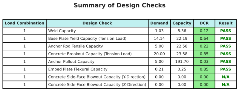
Resumen de diseño
El Software de diseño de placa base de SkyCiv puede generar automáticamente un informe de cálculo paso a paso para este ejemplo de diseño. También proporciona un resumen de los controles realizados y sus proporciones resultantes, Hacer que la información sea fácil de entender de un vistazo. A continuación se muestra una tabla de resumen de muestra, que se incluye en el informe.
Informe de muestra de SkyCiv
Vea el nivel de detalle y claridad que puede esperar de un informe de diseño de placa base SkyCiv. El informe incluye todas las comprobaciones de diseño clave., ecuaciones, y resultados presentados en un formato claro y fácil de leer. Cumple totalmente con los estándares de diseño.. Haga clic a continuación para ver un informe de muestra generado con la calculadora de placa base SkyCiv.
Comprar software de placa base
Compre la versión completa del módulo de diseño de la placa base por sí solo sin ningún otro módulo SkyCiv. Esto le da un conjunto completo de resultados para el diseño de placa base, incluyendo informes detallados y más funcionalidad.