Probablemente esté aquí porque diseñó un anclaje utilizando un software de ingeniería., uno o más controles fallaron, y no estabas seguro de qué cambiar a continuación.
Este tutorial está escrito para nuevos ingenieros y estudiantes de ingeniería que desean comprender modos de falla del anclaje según ACI 318-19 y cómo ajustar un diseño lógicamente. Esto no es un reemplazo del código.. Para disposiciones y requisitos completos, referirse siempre a ACI 318-19 Capítulo 17.
El objetivo aquí es ayudarle a reconocer que esta fallando, por qué está fallando, y qué parámetros de diseño realmente aumentan la capacidad, en lugar de cambiar aleatoriamente las entradas.
Si desea ver cómo se aplican estas comprobaciones paso a paso en un flujo de trabajo de diseño, también puede consultar el Software de diseño de placa base SkyCiv, que informa todas las comprobaciones de anclaje ACI con cálculos completos.
¿Qué es un ancla??
Un ancla suele ser una varilla de acero incrustada en el hormigón para conectar otro elemento estructural., más comúnmente una placa base de acero. Los anclajes transfieren tensión., el cortante, o fuerzas combinadas del acero en el soporte de hormigón..
Los anclajes se clasifican comúnmente por método de instalación..
Anclajes fundidos
Los anclajes moldeados se colocan antes de verter el concreto y se incrustan a medida que el concreto se endurece..
Anclajes postinstalados
Los anclajes postinstalados se instalan en concreto endurecido perforando agujeros y fijando el anclaje usando:
- Expansión mecánica
- Unión adhesiva o química
cual es mejor?
Ningún tipo de ancla es inherentemente mejor. La elección depende de la constructibilidad., restricciones del proyecto, y disponibilidad. Por ejemplo, si se agrega una columna de acero a una losa o zapata existente, los anclajes empotrados ya no son una opción, y normalmente se utilizan anclajes postinstalados.
La disponibilidad también importa, como tipos de anclaje, tamaños, y los límites de instalación dependen del suministro del fabricante.. Los fabricantes de anclajes comunes incluyen Hilti, DeWalt, y pescador, cada uno ofrece diferentes sistemas de anclaje mecánico y adhesivo con datos de diseño y requisitos de instalación específicos del producto..
Anclas individuales frente a grupos de anclas
Cuando fallan las comprobaciones de anclaje, la falla no siempre ocurre en un solo ancla. Dependiendo del diseño, La falla puede ocurrir en un solo anclaje o en un grupo de anclajes que actúan juntos.. ACI 318 hace esta distinción porque el modo de falla y la capacidad que gobiernan pueden ser muy diferentes.
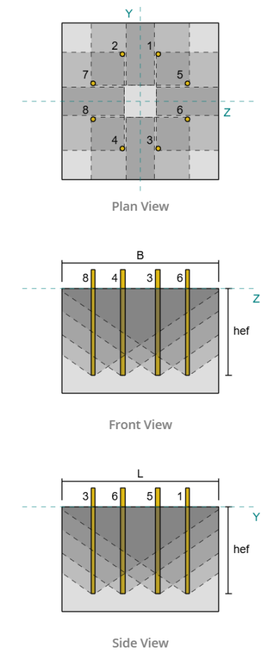
Si una falla se evalúa como una falla de un solo anclaje o un falla del grupo de anclaje depende principalmente de la superposición de superficies de falla proyectadas. Esta superposición generalmente se controla mediante el espaciamiento de los anclajes., profundidad de empotramiento, y distancia al borde.
Para visualizar este comportamiento durante el diseño, herramientas como el Software de diseño de placa base SkyCiv muestra áreas de falla proyectadas y determina automáticamente si los anclajes se evalúan individualmente o como un grupo según la geometría.
Anclas individuales
Si los anclajes están muy espaciados o tienen poca profundidad de empotramiento, sus áreas de falla proyectadas no se superponen. En este caso, La falla se evalúa a nivel de anclaje individual.. Un ancla puede alcanzar su límite sin una contribución significativa de anclas adyacentes..
Grupos de anclaje
Cuando los anclajes se colocan más juntos con suficiente profundidad de empotramiento, sus superficies de falla proyectadas se superponen. En este caso, El hormigón limita la capacidad de todo el grupo., y la falla ocurre cuando el área de falla proyectada combinada alcanza su límite. La capacidad del grupo no es igual a la suma de las capacidades de anclaje individuales..
Esta distinción es fundamental porque varias comprobaciones de tensión y corte de ACI cambian explícitamente dependiendo de si la falla se rige por un solo anclaje o por un grupo de anclajes.. Identificar erróneamente el tipo de falla gobernante puede llevar a diseños poco conservadores o demasiado conservadores..
Ejemplos de diseño
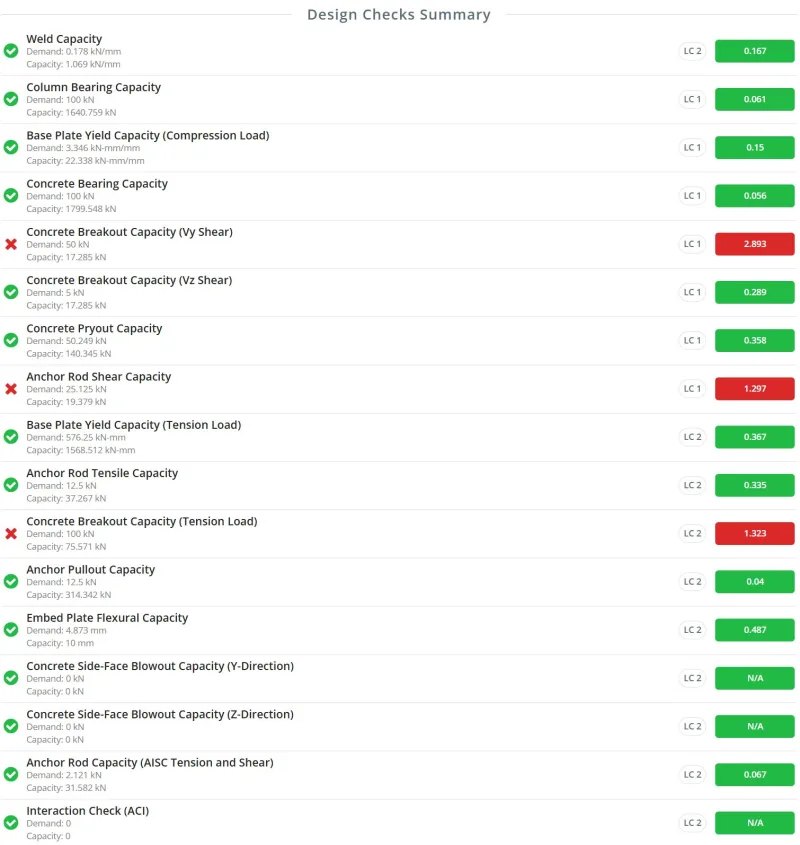
Ejemplos de diseño que ilustran fallas de un solo anclaje y de un grupo de anclajes se puede encontrar en los recursos de diseño de la placa base de SkyCiv. A continuación se muestra un conjunto de muestra de comprobaciones de diseño realizadas por el Software de diseño de placa base SkyCiv.
Verificaciones de tensión del anclaje según ACI 318-19
Cuando los anclajes están sujetos a tensión., ACI 318-19 requiere varios controles. Cada verificación corresponde a un mecanismo de falla física diferente. Una vez que entiendas el mecanismo, se vuelve mucho más fácil ajustar el diseño.
Resistencia del acero en tensión
La verificación del acero del anclaje considera fluencia y rotura del acero del anclaje..
Cómo aumentar la capacidad de tracción del acero
Elija un diámetro de anclaje mayor
Los diámetros más grandes proporcionan un área de tracción más grande. Para selección de diámetro, Muchos ingenieros comienzan en el rango de 1/2 pulgada a 3/4 pulgada. Si la demanda es mayor de lo esperado, aumentar el diámetro. Este juicio mejora con la experiencia..
Aumentar la resistencia del material de anclaje
Las calidades de material más altas aumentan la capacidad pero también aumentan el costo. Los materiales de anclaje comunes incluyen Norma ASTM F1554. Un enfoque de diseño práctico es comenzar con grados inferiores, como Grado 36, luego aumentar a Grado 55 o Grado 105 sólo si lo requiere la demanda.
Proporcionar más anclajes
Si el diámetro del anclaje y la calidad del material ya están maximizados y la verificación de la tensión del acero aún rige, agregar más anclajes en la misma fila puede ser una opción. Por lo general, esto requiere ajustar el espacio, distancias al borde, o dimensiones de la placa base. Se permite agregar filas adicionales, pero cambia la distribución de carga y debe ser evaluado cuidadosamente.
Ecuación de capacidad:
\( NORTE_{a} = A_{se,norte} F_{uta} \)
Resistencia a la rotura del hormigón en tensión
La ruptura del concreto ocurre cuando una porción de concreto en forma de cono se separa del soporte.. En este caso, el acero del anclaje permanece intacto, pero el hormigón circundante falla.
Este modo de falla se aplica a anclajes con cabeza., anclajes de expansión, anclajes de tornillo, y anclajes socavados.
Cómo aumentar la capacidad de rotura del hormigón
Aumentar la profundidad de empotramiento
Se idealiza que el cono de ruptura se extienda desde el extremo incrustado del anclaje hasta la superficie del concreto.. El aumento de la profundidad de empotramiento agranda el cono y aumenta significativamente la capacidad. La profundidad de empotramiento también aumenta directamente la resistencia básica a la rotura definida por ACI..
Aumentar el espacio entre anclajes
Los anclajes muy espaciados restringen el ancho del área de falla proyectada. El aumento del espaciado permite un área de ruptura efectiva más grande, particularmente para grupos de anclaje.
Aumentar la distancia al borde
Los anclajes colocados cerca de los bordes no pueden desarrollar un cono de ruptura completo. El aumento de la distancia al borde a menudo resulta en un aumento notable de la capacidad.
Utilice hormigón de mayor resistencia
La mejora de un hormigón de menor calidad a un hormigón de mayor calidad aumenta la resistencia básica a la rotura y suele ser eficaz cuando la geometría está restringida..
Supongamos hormigón no fisurado cuando sea apropiado.
El hormigón no fisurado proporciona una capacidad ligeramente mayor. Esta suposición sólo debe utilizarse cuando esté justificada., ya que cambia los supuestos de diseño.
Proporcionar refuerzo diseñado para soportar la tensión.
Cuando el refuerzo está diseñado y detallado explícitamente para soportar la fuerza de tensión del anclaje., Se pueden renunciar a los controles de rotura de hormigón.. Esta debe ser una decisión de diseño intencional., no es una suposición.
Ecuación de capacidad para anclajes individuales:
\( NORTE_{cb} = frac{UNA_{Carolina del Norte}}{UNA_{Recuerda}} \Psi_{ed,norte} \Psi_{c,norte} \Psi_{cp,norte} Nótese bien \)
Ecuación de capacidad para grupos de anclaje:
\( NORTE_{cbg} = frac{UNA_{Carolina del Norte}}{UNA_{Recuerda}} \Psi_{CE,norte} \Psi_{ed,norte} \Psi_{c,norte} \Psi_{cp,norte} Nótese bien \)
Fuerza de extracción del ancla
La falla por extracción ocurre cuando el anclaje se saca del concreto sin formar un cono de ruptura completo.. Esta verificación se aplica a anclajes fundidos y ciertos anclajes mecánicos postinstalados y se evalúa para solo anclajes individuales.
Para anclajes postinstalados, La capacidad se determina mediante pruebas experimentales.. Para anclajes empotrados, La capacidad generalmente se basa en las dimensiones del anclaje..
En pernos con cabeza fundida, La capacidad se controla mediante un rodamiento en el extremo integrado., mientras en anclas enganchadas, está controlado por la longitud efectiva del gancho.
Cómo solucionar el fallo de extracción
Utilice placas empotradas más anchas o más gruesas o cabezas de pernos más grandes (Anclas con cabeza)
Para anclajes con extremos empotrados, aumentar el área de rodamiento mejora la capacidad. Cuando se utiliza una placa integrada, aumentar las dimensiones o el espesor de la placa. Para anclajes con cabeza o tuerca empotrada, seleccionar una cabeza o tuerca más grande en el extremo integrado aumenta el área de soporte.
Extienda los ganchos de anclaje o aumente el diámetro de la varilla (Anclas enganchadas)
Los ganchos cortos o las pequeñas barras de anclaje pueden provocar que se salga, incluso si el cono de hormigón no falla. Los ganchos más largos o las varillas más grandes aumentan la capacidad y reducen el riesgo de extracción.
Utilice hormigón de mayor resistencia
La mejora de un hormigón de menor calidad a un hormigón de mayor calidad aumenta la resistencia a la extracción y suele ser eficaz cuando la geometría está restringida..
Utilice hormigón que no se agriete cuando sea apropiado
El hormigón no fisurado proporciona una mejor resistencia al desprendimiento. Esto sólo debe asumirse cuando lo justifiquen las condiciones de diseño..
Las fallas por extracción generalmente se abordan mejorando las condiciones de los rodamientos en lugar de cambiar el espaciado o las distancias de los bordes..
Ecuación de capacidad para encabezados:
\( NORTE_{pn} = Psi_{c,pag} Notario público \)
dónde,
\( N_p = 8A_{brg}f_c’ \)
Ecuación de capacidad para gancho:
\( NORTE_{pn} = Psi_{c,pag} Notario público \)
dónde,
\( N_p = 0.9f_c'e_h d_a \)
Resistencia a la explosión de la cara lateral del concreto
La explosión de la cara lateral ocurre cuando un anclaje con un empotramiento relativamente profundo se coloca demasiado cerca de un borde libre.. En lugar de formar un cono de ruptura hacia arriba, el cono se extiende hacia los lados, causando que la cara lateral del concreto se fracture y explote.
Este modo de falla se rige por la relación entre la profundidad de empotramiento y la distancia al borde.. Cuando estos parámetros se dimensionan de ciertas maneras, este mecanismo de falla puede no aplicarse.
Dado que los conos de hormigón pueden superponerse, Se deben comprobar tanto los anclajes individuales como los grupos de anclaje..
Cómo arreglar una explosión en la cara lateral
Aumentar la distancia al borde
Aumentar la distancia al borde mejora la resistencia nominal. también, una distancia al borde mucho mayor, es decir, ( ca_1 > \frac{h_{ef}}{2.5 }\) hace que este fallo no sea aplicable.
Ajustar el espaciado de anclaje para grupos de anclaje
En grupos ancla, múltiples anclajes pueden causar reventones laterales simultáneos. Separar los anclajes más, sin dejar de permitir cierta superposición de conos, Aumenta el tamaño y la capacidad efectivos del cono de hormigón..
Reducir la profundidad de empotramiento de la varilla de anclaje
Las varillas de anclaje muy largas cerca de los bordes aumentan la probabilidad de que se produzca una explosión.. El uso de varillas más cortas en relación con la distancia al borde puede hacer que esta verificación no sea aplicable..
Utilice hormigón de mayor resistencia
La mejora de un concreto de menor calidad a un concreto de mayor calidad aumenta la resistencia a la explosión de la cara lateral y, a menudo, es eficaz cuando la geometría está restringida..
Ecuación de capacidad para anclajes individuales:
\( NORTE_{sb} = 160c_{a1}\sqrt{UNA_{brg}}\lambda_asqrt{f’_c} \)
Ecuación de capacidad para grupos de anclaje:
\( NORTE_{como} = left(1 + \frac{s}{6C_{a1}}\verdad) NORTE_{sb} \)
Fuerza de unión de anclajes adhesivos
Para anclajes adhesivos postinstalados, La fuerza de unión se verifica bajo fuerzas de tracción.. La capacidad se calcula en función del área de influencia del anclaje adherido y la tensión de unión característica.. Los valores de tensión de unión característicos provienen de pruebas experimentales., y si los datos de la prueba no están disponibles, valores conservadores de ACI 318-19 Tabla 17.6.2.5 puede ser usado.
Dado que las áreas de influencia pueden superponerse, Se deben evaluar tanto los anclajes individuales como los grupos de anclajes..
La capacidad del bono ya representa:
-
La unión entre el anclaje y el adhesivo.
-
La unión entre el adhesivo y el hormigón.
Cómo aumentar la capacidad de los bonos
Aumentar el diámetro del anclaje
Un diámetro de anclaje mayor añade capacidad a la fuerza de unión básica., así como el área de influencia. La geometría del área de influencia está muy influenciada por el diámetro..
Aumentar la profundidad de empotramiento
Una incrustación más profunda aumenta la fuerza de unión básica de un anclaje adhesivo..
Aumentar el espaciado y las distancias al borde
Para grupos de anclajes o anclajes individuales cerca de un borde, El ajuste del espaciado y las distancias de los bordes elimina la limitación del área de influencia total..
Utilice un adhesivo con mayor tensión de unión característica.
Elegir un adhesivo con mayor fuerza de unión mejora la capacidad. Una tensión de unión característica más grande significa un área de influencia más grande, aumentando así la capacidad.
Ecuación de capacidad para anclajes individuales:
\( N_a = frac{UNA_{Ya}}{UNA_{Nao}} \Psi_{ed,Ya} \Psi_{cp,Ya} NORTE_{licenciado en Letras} \)
Ecuación de capacidad para grupos de anclaje:
\( NORTE_{ag} = frac{UNA_{Ya}}{UNA_{Nao}} \Psi_{CE,Ya} \Psi_{ed,Ya} \Psi_{cp,Ya} NORTE_{licenciado en Letras} \)
Comprobaciones de corte de anclaje según ACI 318-19
Capacidad de corte de la varilla de anclaje
Similar a la capacidad de tracción de las varillas de anclaje., La verificación del acero del anclaje considera la fluencia y rotura del acero del anclaje debido a la carga de corte aplicada.. Este modo de falla ocurre cuando se alcanza la resistencia del acero de la varilla de anclaje antes de que falle el concreto circundante..
La capacidad de corte de las varillas de anclaje depende principalmente del diámetro del anclaje., la resistencia del material del acero, y el número de anclajes que resisten la carga aplicada.
Cómo aumentar la capacidad de corte del acero
Elija un diámetro de anclaje más grande
Similar a la resistencia a la tracción del anclaje, La resistencia al corte de los anclajes depende de sus dimensiones físicas.. Al aumentar el diámetro del anclaje se aumenta el área de la sección transversal del acero., lo que resulta en una mayor capacidad de corte.
Aumentar la resistencia del material de anclaje
Si no es posible aumentar el diámetro debido a restricciones geométricas, Se puede considerar la selección de un material de anclaje más resistente.. Los grados comunes de varillas de anclaje incluyen Grado 36, Calificación 55, y grado 105. Los grados de mayor resistencia proporcionan una mayor resistencia a las fuerzas de corte.
Agregar más anclajes
Otro enfoque es aumentar el número de anclajes que resisten la carga.. Agregar más anclajes distribuye la fuerza aplicada entre elementos adicionales y reduce la demanda de corte en cada anclaje individual..
Ecuación de capacidad para anclaje de perno con cabeza fundida:
\( V_{a} = A_{se,V } F_{uta} \)
Ecuación de capacidad para pernos con cabeza fundida y anclajes con pernos de gancho:
\( V_{a} = 0.6A_{se,V } F_{uta} \)
Si hay almohadillas de lechada acumuladas, La resistencia al corte de las varillas de anclaje se reduce en 80 por ciento según disposiciones ACI.
Ruptura del hormigón debido al corte
La resistencia al desprendimiento del concreto en corte ocurre cuando una porción del concreto en forma de cono se separa del soporte debido a las fuerzas de corte aplicadas.. Esta falla puede ocurrir cuando el corte actúa paralelo al borde del concreto o perpendicular al borde..
Las disposiciones de ACI indican que la capacidad de corte paralela a un borde es generalmente mayor que la capacidad de corte actuando perpendicular al borde.. sin embargo, Todavía se recomienda verificar ambas direcciones tal como se implementa en el Software de diseño de placa base SkyCiv.
Cómo aumentar la capacidad de rotura del hormigón
Aumentar la distancia al borde
Aumentar la distancia al borde de los anclajes desde el borde del concreto permite que se desarrolle un cono de ruptura más grande. Cuanto más lejos se coloquen los anclajes del borde, cuanto mayor sea la superficie de falla proyectada. La resistencia básica al corte del hormigón también está directamente relacionada con la distancia al borde..
Aumentar el espacio entre anclajes
Aumentar el espacio entre anclajes permite expandir el área de ruptura proyectada del grupo de anclajes.. Los anclajes muy espaciados restringen el desarrollo del cono de ruptura, mientras que un espaciamiento más grande permite que se forme una superficie de falla más grande.
Aumentar el espesor
El cono de ruptura puede estar limitado por el espesor del soporte de hormigón.. Si el extremo del anclaje está ubicado demasiado cerca de la parte inferior del soporte, el cono de ruptura no puede desarrollarse completamente. Aumentar el espesor del soporte de hormigón permite una proyección de ruptura más completa..
Aumentar la longitud del anclaje
La resistencia básica a la rotura del hormigón al corte está determinada en parte por la longitud de carga del anclaje.. Para anclajes con rigidez constante, esta longitud es generalmente igual a la profundidad de empotramiento del anclaje. Para anclajes de expansión controlados por torque, la longitud de carga generalmente se toma como el doble del diámetro del anclaje. En todos los casos, esta longitud no debe exceder ocho veces el diámetro del anclaje.
Aumentar el diámetro del anclaje
Aumentar el diámetro del anclaje también aumenta la resistencia básica a la rotura del hormigón..
Utilice hormigón de mayor resistencia
El uso de hormigón de mayor resistencia aumenta la resistencia básica a la rotura.. Este enfoque suele ser eficaz cuando los parámetros geométricos como el espaciado o la distancia al borde no se pueden aumentar fácilmente..
Suponga que el concreto no está fisurado cuando sea apropiado
La capacidad de rotura del concreto es ligeramente mayor cuando se supone que el concreto no está agrietado.. Esta suposición sólo debe utilizarse cuando lo justifiquen las condiciones de diseño..
Proporcionar refuerzo diseñado para soportar tensión.
Si el refuerzo está diseñado y detallado intencionalmente para soportar las fuerzas del anclaje., Se puede evitar que la ruptura del concreto gobierne. Cuando se proporciona un refuerzo diseñado adecuadamente, ACI permite que se renuncie al cheque de ruptura.
Ecuación de capacidad para anclajes individuales:
\( V_{cb} = frac{UNA_{U}}{UNA_{vco}} \psi_{ed,V } \psi_{c,V } \psi_{h,V } V_B \)
Ecuación de capacidad para grupos de anclaje.:
\( V_{cbg} = frac{UNA_{U}}{UNA_{vco}} \psi_{CE,V } \psi_{ed,V } \psi_{c,V } \psi_{h,V } V_B \)
Desprendimiento del hormigón debido al corte
El desprendimiento del concreto es otro modo de falla asociado con anclajes sujetos a corte.. Esta falla ocurre cuando el anclaje tira una porción de concreto en forma de cuña hacia arriba debido a la fuerza de corte aplicada..
Según disposiciones ACI, La resistencia al desprendimiento del hormigón está relacionada con la resistencia al desprendimiento del hormigón en tensión.. Este modo de falla se aplica a varios tipos de anclajes, incluidos los anclajes con cabeza., anclajes de expansión, anclajes de tornillo, y anclajes socavados.
Cómo aumentar la capacidad de extracción del hormigón
Aumentar la profundidad de empotramiento
Se idealiza que el cono de ruptura se extienda desde el extremo incrustado del anclaje hasta la superficie del concreto.. Al aumentar la profundidad de empotramiento se agranda este cono y se aumenta significativamente la capacidad de extracción.. La profundidad de empotramiento también aumenta la resistencia básica a la rotura definida por ACI.. Adicionalmente, una mayor profundidad de empotramiento da como resultado una mayor kcp factor utilizado en el cálculo de la resistencia al desprendimiento, lo que aumenta aún más la capacidad de extracción.
Aumentar el espacio entre anclajes
Los anclajes muy espaciados restringen el área de ruptura proyectada. Aumentar el espacio entre anclajes permite desarrollar un área de ruptura efectiva más grande., especialmente para grupos ancla.
Aumentar la distancia al borde
Los anclajes ubicados cerca de los bordes no pueden desarrollar un cono de ruptura completo. Aumentar la distancia al borde permite que la superficie de ruptura se expanda y mejora la capacidad de extracción.
Utilice hormigón de mayor resistencia
El uso de hormigón de mayor resistencia aumenta la resistencia básica a la rotura y puede mejorar la capacidad de extracción cuando los parámetros geométricos no se pueden modificar..
Suponga que el concreto no está fisurado cuando sea apropiado
El hormigón no fisurado proporciona una capacidad ligeramente mayor. Esta suposición sólo debe utilizarse cuando lo justifiquen las condiciones de diseño..
Ecuación de capacidad para anclajes individuales:
\( V_{cp} = k_{cp} NORTE_{cp} \)
Ecuación de capacidad para grupos de anclaje.:
\( V_{cpg} = k_{cp} NORTE_{cpg} \)
Comprobaciones de tensión del anclaje y de interacción de corte según ACI 318-19
Esta sección se publicará próximamente..