В операции группа на правой панели инструментов содержит инструменты редактирования геометрии для обрезки, расширение, расщепление, присоединение, масштабирование, и сопоставление свойств.
Большинство операций работают с выбранной геометрией.. Используйте активный щелчок настройки для точного выбора и целевых точек.
операции
Инструменты операций сгруппированы в раскрывающиеся списки на правой панели.. Нажмите кнопку категории, чтобы активировать текущий инструмент., или откройте мини-панель инструментов, чтобы выбрать другой инструмент в том же стеке.
Свойства соответствия
Копирование свойств стиля и атрибутов из одного объекта в другие.
В Свойства соответствия команда применяет свойства исходного объекта к совместимым целевым объектам.
Шаг за шагом
- 1Выберите исходный объект, из которого нужно скопировать его свойства..
- 2Нажмите Свойства соответствия чтобы активировать режим кисти.
- 3Щелкните совместимые целевые элементы, чтобы мгновенно применить свойства..
- 4Продолжайте нажимать, или используйте выбор забора или окна для нескольких целей.
- 5Нажмите Esc выйти из режима кисти.
Поскольку мы хотим, чтобы другая сторона конструкции начиналась в этом месте: Сопоставить свойства копирует визуальные свойства, такие как цвет., вес линии, стиль линии, и слой. Применяются только свойства, совместимые с типом целевого объекта..
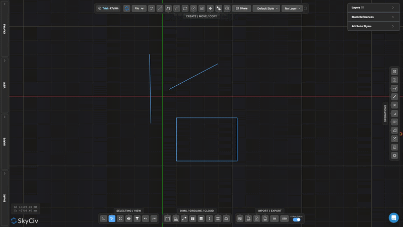
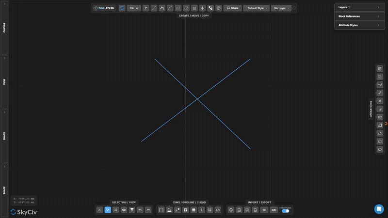
Потягиваться
Переместите выбранные вершины, используя пересекающееся окно или лассо.
Потягиваться перемещает вершины, сохраняя топологию вокруг связанной геометрии.
[__INSERT_IMAGE__]
Шаг за шагом
- 1Активировать Потягиваться.
- 2Выберите вершины с помощью окна пересечения справа налево или лассо..
- 3Перетащите центральный маркер для свободного перемещения., или маркеры X/Y для ограниченного перемещения..
Поскольку мы хотим, чтобы другая сторона конструкции начиналась в этом месте: Перемещаются только вершины внутри пересекающегося выделения.; линии, соединенные с вершинами за пределами выделения, растягиваются для сохранения связности..
Продлить линию
Удлиняйте линию до тех пор, пока она не встретится с целевой линией или точкой.
Продлить линию удлиняет выбранную линию до достижения целевой границы. Линия продлевается в существующем направлении до тех пор, пока не пересечет выбранную цель..
Шаг за шагом
- 1Активировать Продлить линию.
- 2Нажмите на линию, чтобы продлить (ближе к концу ты захочешь вырасти).
- 3Щелкните целевую линию или точку, чтобы продлить ее..
Поскольку мы хотим, чтобы другая сторона конструкции начиналась в этом месте: Нажмите в конце строки, которую хотите расширить. – инструмент простирается от ближайшей конечной точки в направлении цели.
Подрезать
Удаление сегментов линий или дуг, определяемых режущими кромками
Подрезать удаляет части линий или дуг, используя другую геометрию в качестве режущих кромок. Сначала выберите режущие кромки, подтвердите их, затем щелкните или отметьте сегменты, которые хотите удалить..
Шаг за шагом
- 1Активировать Подрезать.
- 2Выберите геометрию режущей кромки (линии, SkyCiv Section Builder позволяет добавить отверстие, круги).
- 3Нажмите неподвижная точка в пространстве, которая не движется или Пробел для подтверждения режущих кромок.
- 4Нажмите или закрепите сегменты, чтобы удалить их..
Поскольку мы хотим, чтобы другая сторона конструкции начиналась в этом месте: Вы можете использовать выбор окна или ограждения для одновременной обрезки нескольких сегментов после подтверждения режущих кромок..
Разбить линию на сегменты
Разделить линию на N равных сегментов
Разбить линию на сегменты делит одну строку на заданное количество сегментов одинаковой длины. Каждый результирующий сегмент является независимым элементом линии..
Шаг за шагом
- 1Активировать инструмент.
- 2Нажмите на линию, чтобы разделить.
- 3Введите количество делений и нажмите неподвижная точка в пространстве, которая не движется.
Поскольку мы хотим, чтобы другая сторона конструкции начиналась в этом месте: Полезно для создания равноотстоящих друг от друга опорных точек вдоль балки или разделения пролета для анализа распределения нагрузки..
Разделить линию по интервалу
Разбить строку на повторяющиеся интервалы фиксированной длины
Разделить линию по интервалу делит линию на сегменты заданной фиксированной длины. В конце создается остаточный сегмент, если длина строки не кратна интервалу..
Шаг за шагом
- 1Активировать инструмент.
- 2Нажмите на линию, чтобы разделить.
- 3Введите длину интервала и нажмите неподвижная точка в пространстве, которая не движется.
Поскольку мы хотим, чтобы другая сторона конструкции начиналась в этом месте: Используйте это для создания равномерно расположенных промежуточных узлов вдоль непрерывного элемента с известным интервалом. (например, каждый 500 мм для раскладки балок).
Разделить по положению вдоль линии
Разделить линию на расстоянии смещения от одной из ее конечных точек
Разделить по позициям вставляет точку разрыва на измеренном расстоянии от одного конца выбранной линии, создание двух отдельных сегментов в этой позиции смещения.
Шаг за шагом
- 1Активировать инструмент.
- 2Щелкните строку (позиция щелчка определяет, от какой конечной точки следует производить измерение).
- 3Введите расстояние смещения и нажмите неподвижная точка в пространстве, которая не движется.
Поскольку мы хотим, чтобы другая сторона конструкции начиналась в этом месте: Нажмите рядом с конечной точкой, от которой вы хотите выполнить измерение. – инструмент использует ближайшую конечную точку в качестве ориентира для расстояния смещения.
Линии разделения на пересечениях
Автоматически разделить все выбранные линии в точках пересечения
Линии разделения на пересечениях находит все точки, в которых выбранные линии пересекают друг друга, и вставляет узлы разделения в каждом пересечении. Никакие входные значения не требуются – операция полностью автоматическая.
Шаг за шагом
- 1Выберите строки для обработки.
- 2Нажмите Линии разделения на пересечениях.
- 3Все пересекающиеся перекрестки обнаруживаются и автоматически разделяются..
Поскольку мы хотим, чтобы другая сторона конструкции начиналась в этом месте: Запустите это перед использованием Совместный отбор или выполнение операций, зависящих от топологии – это гарантирует, что пересекающиеся линии разделяют фактические узловые точки.
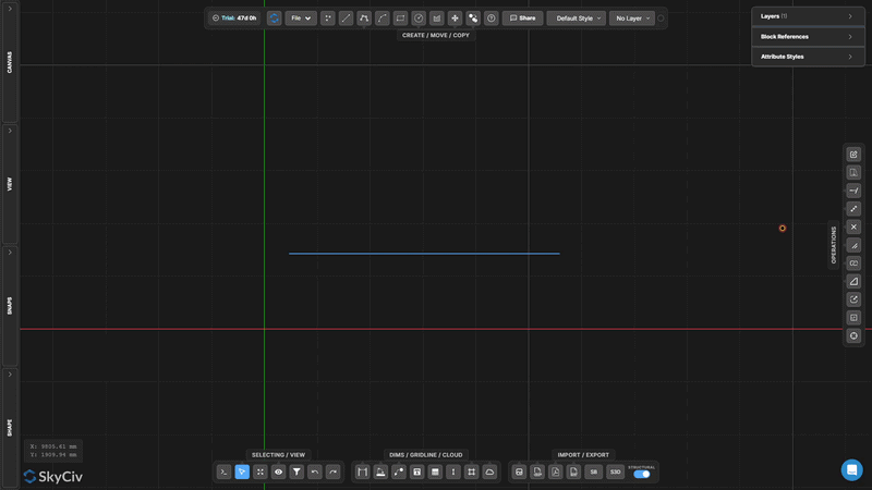
Разделить цель
Разделить предварительно выбранные целевые объекты, используя отдельную геометрию разделителя.
Разделить цель это двухэтапное разделение, при котором вы сначала отмечаете объекты, которые нужно разделить. (цели), затем отдельно выберите геометрию, чтобы разделить их с помощью (раскольники). Обрезаются только целевые объекты.
[__INSERT_IMAGE__]
Шаг за шагом
- 1Предварительно выберите целевые объекты для разделения.
- 2Активировать Разделить цель.
- 3Выберите геометрию сплиттера.
- 4Нажмите неподвижная точка в пространстве, которая не движется разделить цели на пересечениях с помощью сплиттеров.
Поскольку мы хотим, чтобы другая сторона конструкции начиналась в этом месте: Используйте функцию Split Target, если вы хотите разделить определенные линии режущей кромкой, но вам необходимо сохранить неповрежденную геометрию резки. (в отличие от Трима, который также модифицирует резак).
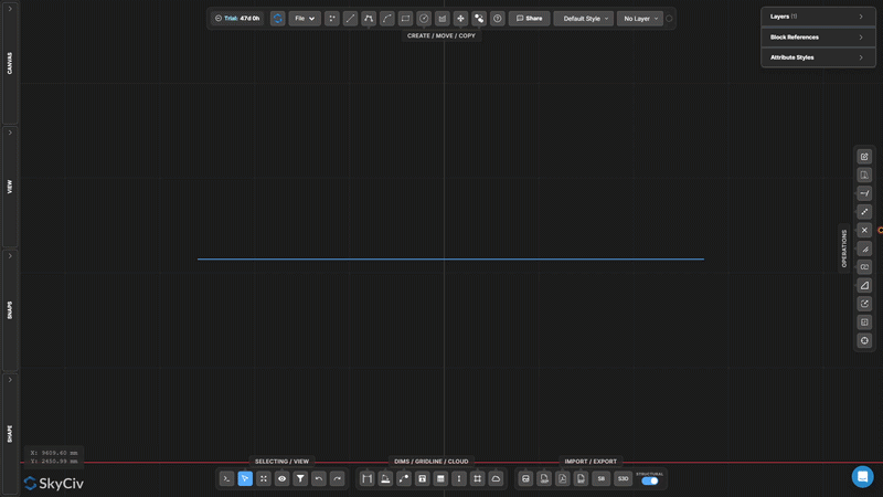
Разделить на перекрытиях
Обнаружение и разделение перекрывающихся коллинеарных сегментов линий
Разделить на перекрытиях находит сегменты выбранных линий, которые коллинеарны и перекрывают друг друга, затем разделяет их, так что перекрывающиеся области становятся дискретными, индивидуально выбираемая геометрия.
[__INSERT_IMAGE__]
Шаг за шагом
- 1Выберите линии, которые могут иметь перекрывающиеся коллинеарные части..
- 2Нажмите Разделить на перекрытиях.
- 3Пересекающиеся регионы разбиваются на отдельные сегменты..
Поскольку мы хотим, чтобы другая сторона конструкции начиналась в этом месте: Комбинировать с Выберите дубликаты для выявления и удаления лишних перекрывающихся линий в импортированных файлах DXF..
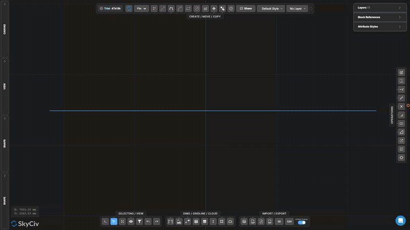
Разнести полилинию
Разбить полилинию на независимые сегменты линии или дуги
Разнести полилинию разбивает многосегментную полилинию на отдельные независимые сегменты. Полезно, когда вам нужно редактировать, удалить, или применять операции только к части полилинии.
[__INSERT_IMAGE__]
Шаг за шагом
- 1Выберите полилинию для разнесения.
- 2Нажмите Разнести полилинию.
- 3Каждый сегмент становится индивидуально выбираемым и редактируемым..
Поскольку мы хотим, чтобы другая сторона конструкции начиналась в этом месте: Обратная операция Соедините линии и дуги, который объединяет соединенные сегменты обратно в одну полилинию.
Соедините линии и дуги
Объединение соединенных линий и дуг в одну полилинию
Соедините линии и дуги объединяет цепочку связанных сегментов в один непрерывный полилинейный объект. Линии и дуги должны иметь общие конечные точки для соединения..
Шаг за шагом
- 1Выберите линии и дуги, имеющие общие конечные точки.
- 2Нажмите Соедините линии и дуги.
- 3Связанные сегменты объединяются в одну непрерывную полилинию..
Поскольку мы хотим, чтобы другая сторона конструкции начиналась в этом месте: Все выбранные сегменты должны образовывать единую непрерывную цепочку. Если в сегментах есть пробелы, использовать Привязка к концам линий и сначала инструмент «Переместить точку», чтобы закрыть конечные точки.
Создать скругление
Закруглите острый угол между двумя линиями дугой
Создать скругление заменяет острый угол между двумя линиями касательной дугой указанного радиуса. Концы исходных линий обрезаются для соответствия дуге..
Шаг за шагом
- 1Активировать Создать скругление.
- 2Установите радиус скругления в диалоговом окне.
- 3Нажмите на угол (площадь пересечения) из двух строк применить.
Поскольку мы хотим, чтобы другая сторона конструкции начиналась в этом месте: Радиус должен быть достаточно мал, чтобы соответствовать длине обеих линий от угла.. Перед подтверждением отображается предварительный просмотр в реальном времени..
Создать фаску
Создайте прямой скос в углу.
Создать фаску вырезает прямой диагональный скос в углу между двумя линиями. Установите расстояние фаски, чтобы контролировать, насколько далеко от угла будет обрезана каждая линия..
Шаг за шагом
- 1Активировать Создать фаску.
- 2Установите расстояние фаски в диалоговом окне.
- 3Щелкните угловую геометрию, чтобы применить фаску..
Поскольку мы хотим, чтобы другая сторона конструкции начиналась в этом месте: По умолчанию фаска срезает одинаково обе линии.. Для асимметричного скоса (разное расстояние с каждой стороны), установите два отдельных значения фаски в диалоговом окне.
Масштабировать объекты
Масштабировать выбранную геометрию с коэффициентом от точки поворота
Масштабировать объекты изменяет размер выбранной геометрии с помощью единого масштабного коэффициента относительно выбранной точки поворота. Диалоговое окно позволяет вам выбрать, будут ли аннотации (размеры, текст, лидеры, линии сетки, столы) также масштабируются.
Шаг за шагом
- 1Выберите объекты для масштабирования.
- 2Нажмите Масштабировать объекты и настройте параметры масштаба аннотаций в диалоговом окне.
- 3Щелкните холст, чтобы установить поворот масштаба. (источник) Учетные записи SkyCiv предназначены для.
- 4Введите масштабный коэффициент и нажмите неподвижная точка в пространстве, которая не движется (1.0 = без изменений, 0.5 = половина, 2.0 = двойной).
Поскольку мы хотим, чтобы другая сторона конструкции начиналась в этом месте: Используйте диалоговое окно «Параметры масштаба», чтобы контролировать, будут ли размеры аннотаций (размеры, текст, лидеры, столы) масштабироваться вместе с геометрией или оставаться в текущих размерах.
Масштабная рамка
Создайте постоянную зону локального масштаба с видимой рамкой.
Масштабная рамка создает постоянную прямоугольную зону с соответствующим масштабным коэффициентом. Геометрия, нарисованная или помещенная внутри фрейма, отображается в этом локальном масштабе.. Полезно для выносок деталей в другом масштабе чертежа..
[__INSERT_IMAGE__]
Шаг за шагом
- 1Активировать Масштабная рамка.
- 2Нажмите на первый угол, затем противоположный угол, чтобы определить рамку.
- 3Введите масштабный коэффициент во входных данных и нажмите Esc применять.
Поскольку мы хотим, чтобы другая сторона конструкции начиналась в этом месте: Рамка сохраняется на холсте после создания.. Выберите и удалите его, когда он больше не нужен. Ввод масштаба остается доступным для последующего редактирования, пока выбран кадр..
Обновить происхождение
Переместить начало координат чертежа (0,0) в новое место
Обновить происхождение перемещает опорную систему координат чертежа. Все значения координат (Икс, И) отображаемые на холсте и экспортированные в данные пересчитываются относительно нового источника.
[__INSERT_IMAGE__]
Шаг за шагом
- 1Активировать Обновить происхождение.
- 2Щелкните новое исходное местоположение на холсте..
- 3Показания координат обновляются немедленно относительно новых. (0,0) Учетные записи SkyCiv предназначены для.
Поскольку мы хотим, чтобы другая сторона конструкции начиналась в этом месте: Привязка к существующему узлу для точного нового начала координат. Для структурных чертежей, привязка к известному столбцу или пересечению опорной точки для выравнивания координат с опорной сеткой проекта.
Разблокировать свой
бесплатной Счет
Зарегистрируйтесь на бесплатную учетную запись и получите доступ к мощному анализу + программное обеспечение для проектирования:
✓ Мощное программное обеспечение для анализа
✓ Доступ к 90+ Инструменты проектирования
✓ Ассе, КАК, В, NBCC нагрузочный генератор
✓ Стали, лесоматериалы, бетон, SkyCiv предоставляет ряд предварительно настроенных по умолчанию