
Пример дизайна базовой пластины с использованием AISC 360-22 и ACI 318-19
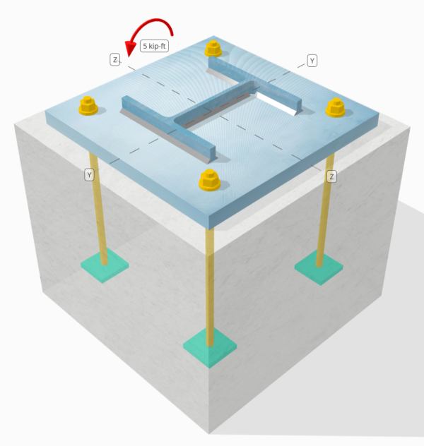
Запись о проблеме
Определите, достаточно ли разработанного соединения с столбцами-базой для 5 kip-ft strong-axis moment.
Данные данных
Столбец:
Раздел столбца: W8x31
Область столбца: 9.130 в2
Материал столбца: A992
Опорная плита:
Размеры опорной плиты: 15 в х 15 в
Толщина опорной плиты: 1 в
Материал опорной плиты: A36
бетон:
Бетонные размеры: 18 в х 18 в
Бетонная толщина: 15 в
Бетонный материал: 3000 фунтов на квадратный дюйм
Швы:
Размер сварного шва: 1/4 в
Классификация металла наполнителя: Е70XX
Нагрузка сжатия переносится только через сварные швы? НЕТ
Модель в бесплатном инструменте SkyCiv
Смоделируйте конструкцию опорной плиты, указанную выше, с помощью нашего бесплатного онлайн-инструмента сегодня.! Регистрация не требуется.
Determine if Low Moment or Large Moment
The calculations for this base plate example, which is subjected to a strong-axis moment, will be based on Руководство по проектированию AISC 1, 3Rd Edition. According to the design guide, base plates subjected to moment loads only are classified as the Large Moment Case. This is because no axial load is present to counteract the eccentric load acting on the connection.
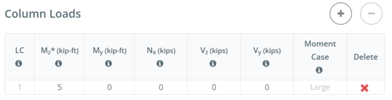
For other load combinations, such as strong-axis bending with axial compression or strong-axis bending with axial tension, determining if the case is Large Moment or Low Moment depends on the actual размер столбца, base plate size, concrete size, and the given грузы.
In the free version of SkyCiv, the moment case is displayed as you enter the load values. You can access the free tool here to determine the moment case yourself. Straight from the browser, установка не требуется.
To learn more about Low Moment and Large Moment case, refer to this SkyCiv article: АИСЦ ДГ1: Опорные пластины с большим моментом и низким моментом
Пошаговые расчеты
Проверьте #1: Weld capacity
We start the design by checking the weld capacity of the connection. We use the Blodgett equations from Проектирование сварных конструкций Омер В.. Blodgett to determine the weld section modulus of the weld. We take the weld shape shown below as a simplification.
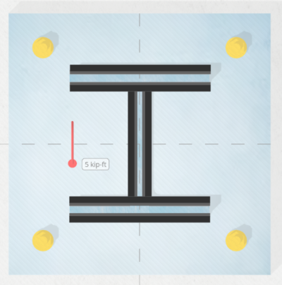
\(S_w = 2d_{col}b_f + \dfrac{(d_{col})^2}{3} = 2 \times 8 \text{ in} \times 8 \text{ in} + \dfrac{(8 \text{ in})^2}{3} = 149.33 \text{ in}^2\)
следующий, we divide the applied bending moment by the weld section modulus to determine the weld stress per unit length. Note that in calculating the weld section modulus, we assume the critical weld stresses occur at the outermost fiber. For a weld in an I-shaped section, the critical locations are at the outer flanges. We get the weld stress as:
\(r_{uw} = \dfrac{M_z}{S_w} = \dfrac{5 \text{ kip·ft}}{149.33 \text{ in}^2} = 0.40179 \text{ kip/in}\)
затем, мы рассчитываем capacity of the weld. Для 0.25 in weld size, the design weld throat is 0.177 в, which is obtained by multiplying the weld size by \(\dfrac{\sqrt{2}}{2}\). С использованием Aisc 360-22 уравнение. J2-4, the weld capacity per unit length is:
\(\phi r_n = \phi 0.6F_{exx}E_w k_{ds} = 0.75 \times 0.6 \times 70 \text{ ksi} \times 0.177 \text{ in} \times 1 = 5.5755 \text{ kip/in}\)
поскольку 0.40179 КПИ < 5.5755 КПИ , the column weld capacity is достаточный.
This weld check investigates the weld stress at the tension flange. Since the geometry is symmetric and the only load is a moment acting at the center, we can assume the stress at the compression flange is the same as the stress at the tension flange. Следовательно, the welds at the compression flange also have enough capacity.
В этом примере дизайна, тем не мение, the design inputs specify that compression is not transferred through the welds, but through несущий. таким образом, in the next check, we evaluate the bearing capacity of the column.
Проверьте #2: Calculate column bearing capacity
After evaluating the weld capacity, we make sure the column has enough capacity to bear on the base plate. This is necessary because we assume the welds do not carry the compression load.
Первый, Мы определяем compressive stress at the critical section, which is still the flange. We then add any contribution from axial compression. В таком случае, there is none.
\(r_u = \dfrac{N_x}{A_{col}} + \dfrac{M_z 0.5d_{col}}{I_{zz,col}} = \dfrac{0 \text{ kip}}{9.13 \text{ in}^2} + \dfrac{5 \text{ kip·ft} \times 0.5 \times 8 \text{ in}}{110 \text{ in}^4} = 2.1818 \text{ ksi}\)
затем, мы используем Aisc 360-22 Section J7 Eq. J7-1 Чтобы определить несущая способность:
\(\phi r_n = \phi 1.8F_{y\_col} = 0.75 \times 1.8 \times 50 \text{ ksi} = 67.5 \text{ ksi}\)
поскольку 2.1818 KSI < 67.5 KSI, емкость с столбцом достаточный.
Обычно, this check is not governing.
Проверьте #3: Рассчитать бетонную способность
To calculate the concrete bearing capacity, we need two areas. See the figure below as a guide.
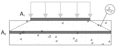
- A1 – Base plate loaded area
- A2 – Area of the concrete support with the same shape as A1
А1 это loaded area of the base plate, пока A2 это same loaded area projected at a 2H:1V slope into the concrete support. More details on these areas can be found in Аси 318-19 Раздел 22.8.3.2.
В этом base plate design with moment, the A1 area will be calculated using the full width of the base plate, \(B\) и actual bearing length, \(Y\). The actual bearing length is measured from the edge of the base plate at the compression side towards the center of the plate.
\( A_1 = B \times Y \)
For most engineers, calculating A1 and A2 requires a lot of work, so they simply assume A1 = A2, который является консервативным. Нелинейный или статический анализ второго порядка подходит, когда конструкция демонстрирует нелинейное поведение. Skyciv Base Plate Software, итерации are performed to determine the actual A1 values and to maximize the capacity of the base plate.
The table below shows the iteration steps from SkyCiv to determine the bearing length Y, и впоследствии, to determine the actual A1 and A2 areas.

Первый, an initial Y is assumed, and the A2 and A1 values are calculated based on the initial Y. These are then used to calculate the maximum bearing strength of the concrete, \(f_{p\_max}\), и соответствующий bearing force per unit length, \(q_{max}\). Once these are determined, the corresponding Y value is determined based on уравнение. 4-32 of AISC DG1 3р-д Версия. If the calculated Y does not match the initial Y, another iteration step is performed. A more detailed step-by-step calculation of the last iteration is shown in the next section.
Сейчас же, taking the A2 and A1 values from the iteration, мы используем уравнение. 4-2 of AISC Design Guide 1, 3Rd Edition, to determine \(f_{p\_max}\), the design bearing strength for concrete crushing:
\(f_{p\_max} = \phi \left( \min \left( 0.85 \, (f_c’) \sqrt{\dfrac{A_2}{A_1}}, \, 1.7 \, (f_c’) \right) \right)\)
\(f_{p\_max} = 0.65 \times \left( \min \left( 0.85 \times (3 \text{ ksi}) \times \sqrt{39.941}, \, 1.7 \times (3 \text{ ksi}) \right) \right) = 3.315 \text{ ksi}\)
Дополнительно, since this design is a Large Moment Case, the base plate has both a compression side and a tension side. В этой ситуации, we should allow the concrete bearing to be at its full capacity and minimize the Y value. Так, any remaining tensile force, based on equilibrium of forces, will be taken by the anchors at the tension side.
Given this, we set \(f_{p\_actual}\) равно \(f_{p\_max}\).
\(f_{p\_actual} = f_{p\_max} = 3.315 \text{ ksi}\)
поскольку 3.315 ksi ≤ 3.315 KSI, бетонная способность достаточный.
Проверьте #4: Calculate base plate yielding capacity at the bearing interface
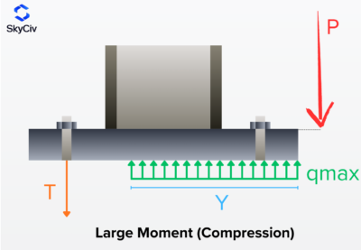
The next step is to determine if the base plate has enough capacity for the given load. As the moment load pushes the base plate against the concrete, the base plate has a tendency to yield due to flexure. We call this check the base plate yielding check on the bearing interface. There is also a separate yielding due to the tension load, and it will be covered in the next design check.
To check the base plate yielding, we need to determine the \(q_{max}\), which is the compression force per unit length. AISC DG1 3rd Ed. уравнение. 4-37 дает \(q_{max}\)так как:
\(q_{max} = f_{p\_max}B_{bp} = 3.315 \text{ ksi} \times 15 \text{ in} = 49.725 \text{ kip/in}\)
затем, we will calculate the Y-dimension. Although the Y-dimension is already calculated in the prior check, this section will show how we use the equations from AISC DG1. For this Large Moment Case, мы используем уравнение. 4-32 of AISC DG1, 3Rd Edition.
For the plus case:
\(Y_{case1} = \left( f + \dfrac{L_{bp}}{2} \right) + \sqrt{\left( \left( f + \dfrac{L_{bp}}{2} \right)^2 \right) – \dfrac{2M_z}{q_{max}}}\)
\(Y_{case1} = \left( 5.5315 \text{ in} + \dfrac{15 \text{ in}}{2} \right) + \sqrt{\left( \left( 5.5315 \text{ in} + \dfrac{15 \text{ in}}{2} \right)^2 \right) – \dfrac{2 \times 5 \text{ kip·ft}}{49.725 \text{ kip/in}}}\)
\(Y_{case1} = 25.97 \text{ in}\)
For the minus case:
\(Y_{case2} = \left( f + \dfrac{L_{bp}}{2} \right) – \sqrt{\left( \left( f + \dfrac{L_{bp}}{2} \right)^2 \right) – \dfrac{2M_z}{q_{max}}}\)
\(Y_{case2} = \left( 5.5315 \text{ in} + \dfrac{15 \text{ in}}{2} \right) – \sqrt{\left( \left( 5.5315 \text{ in} + \dfrac{15 \text{ in}}{2} \right)^2 \right) – \dfrac{2 \times 5 \text{ kip·ft}}{49.725 \text{ kip/in}}}\)
\(Y_{case2} = 0.092925 \text{ in}\)
Note that this equation has + и – символы, so we get two values. Отсюда, we need to determine which value makes more sense. поскольку 25.97 в is greater than the base plate length, 15 в, we will not consider this value. Так, мы будем использовать 0.092925 в as the длина подшипника.
\(Y = Y_{case2} = 0.092925 \text{ in}\)
следующий, we calculate the cantilever lengths. Эти m and n dimensions from the figure below. Это основано на AISC DG1 3rd Edition Section 4.3.1.
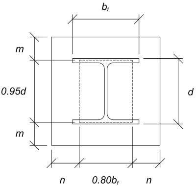
The calculated m and n cantilever values are:
\(m = \dfrac{L_{bp} – 0.95d_{col}}{2} = \dfrac{15 \text{ in} – 0.95 \times 8 \text{ in}}{2} = 3.7 \text{ in}\)
\(n = \dfrac{B_{bp} – 0.8b_f}{2} = \dfrac{15 \text{ in} – 0.8 \times 8 \text{ in}}{2} = 4.3 \text{ in}\)
затем, мы будем compare the calculated Y value to the larger of m and n. Since Y is less than the larger cantilever length, мы будем использовать AISC DG1 3rd Ed. уравнение. 4-52а . This gives the required base plate thickness to be:
\(t_{p(req)} = \sqrt{\dfrac{4f_{p\_actual}Y \left( n – \dfrac{Y}{2} \right)}{\phi F_{y\_bp}}}\)
\(t_{p(req)} = \sqrt{\dfrac{4 \times 3.315 \text{ ksi} \times 0.092925 \text{ in} \times \left( 4.3 \text{ in} – \dfrac{0.092925 \text{ in}}{2} \right)}{0.9 \times 36 \text{ ksi}}} = 0.4022 \text{ in}\)
В завершение, let’s compare it to the actual base plate thickness.
\(t_{p(actual)} = t_{bp} = 1 \text{ in}\)
поскольку 0.4022 в < 1 в, the yielding capacity of the base plate is достаточный.
Проверьте #5: Calculate base plate yielding capacity at the tension interface
The required tensile force on the anchors at the tension side is equal to the resulting compression force on the compression side. This is because the base plate is only loaded with moment loads, and so the resulting couple forces are equal in magnitude.
To calculate the required strength of anchors, мы используем AISC DG1 3rd Ed. уравнение. 4-31.
\(T_u = q_{max}Y = 49.725 \text{ kip/in} \times 0.092925 \text{ in} = 4.6207 \text{ kip}\)
затем, мы рассчитываем eccentricity of this tensile force from the column support. This is taken from the center of the anchor rod to the center of the column flange. Мы используем уравнение. 4-61 of the design guide to determine the eccentricity. In the equation, f is the distance of the anchor rod from the column centerline.
\(x = \left( f – \dfrac{d_{col}}{2} \right) + \dfrac{t_f}{2} = \left( 5.5315 \text{ in} – \dfrac{8 \text{ in}}{2} \right) + \dfrac{0.435 \text{ in}}{2} = 1.749 \text{ in}\)
Note that in this analysis, we take the whole base plate width as the section to resist the flexure, as we closely follow the AISC DG1 3rd Ed. guidelines. Other conservative bending widths could also be used.
В завершение, we determine the required base plate thickness с использованием уравнение. 4-62а .
\(t_{p(req)} = \sqrt{\dfrac{4T_u x}{B_{bp}\phi F_{y\_bp}}} = \sqrt{\dfrac{4 \times 4.6207 \text{ kip} \times 1.749 \text{ in}}{15 \text{ in} \times 0.9 \times 36 \text{ ksi}}} = 0.25791 \text{ in}\)
поскольку 0.25791 в < 1 в, в yielding capacity of the base plate is достаточный.
Проверьте #6: Проверки анкеров
The rest of the anchor design checks are not shown in this example. Please refer to other SkyCiv Base Plate Design Examples that covers capacity of якорная стоянка.
Резюме дизайна
Программное обеспечение для проектирования базовых плитов Skyciv может автоматически генерировать пошаговый отчет расчета для этого примера проекта. Это также предоставляет краткую информацию о выполненных чеках и их полученных соотношениях, Облегчение информации для понимания с первого взгляда. Ниже приведена примерная сводная таблица, который включен в отчет.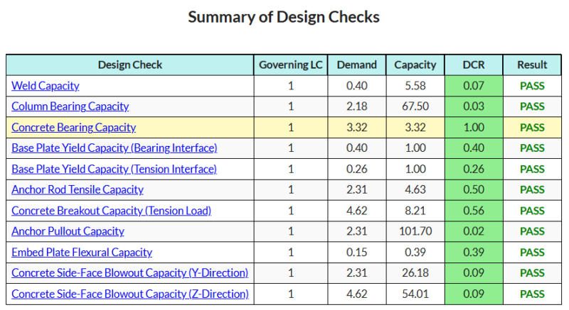
Покупка программного обеспечения для базовой пластины
Купите полную версию модуля дизайна базовой плиты без каких -либо других модулей Skyciv. Это дает вам полный набор результатов для дизайна базовой плиты, в том числе подробные отчеты и больше функциональности.

