Ваш путеводитель по программному обеспечению SkyCiv — учебные пособия, практические руководства и технические статьи
Экспорт в Structural 3D
Model and Export Structural Geometry Directly to S3D
CloudCAD allows you to create structural geometry directly within CAD and export it to Structural 3D (S3D). By assigning structural data to points, lines and hatch regions, CloudCAD understands how each element should be interpreted during export. This guide covers the complete workflow, from assigning structural properties through to reviewing and exporting your model.
Structural Geometry Types
CloudCAD uses different geometry types to represent different structural element during export:
Geometry Type
Structural Objects
Очки
Columns or Supports
Линии
Балки
Hatch Regions
Тарелки
Export Workflow
Before exporting to S3D, structural geometry follows a simple four-step workflow:
шаг 1
Геометрия
Поверните вид, чтобы можно было легко выбрать две общие стропила с помощью выбора слева направо.
шаг 2
Structural Data
Поверните вид, чтобы можно было легко выбрать две общие стропила с помощью выбора слева направо.
шаг 3
Обзор
Поверните вид, чтобы можно было легко выбрать две общие стропила с помощью выбора слева направо.
шаг 4
Экспорт в S3D
Before geometry can be exported to S3D, CloudCAD needs to understand how each element should behave structurally. This is achieved by assigning structural properties to points, lines and hatch regions, allowing them to be exported as supports, столбцы, beams and plates within the final model.
Structural Mode
Control how geometry behaves during structural export
Structural Mode is enabled by default, meaning newly created geometry is automatically assigned structural properties and included during export.
STRUCTURAL MODE CONTROLS
Использовать Structural Mode togglein the bottom-right corner of the screen.
Press the default shortcutS3.
Заметка:When Structural Mode is disabled, geometry behaves as drafting geometry only and will not be included when exporting to S3D.
Назначение опор
Apply support restraints to points in your model
Supports define how a structure is restrained and can only be applied to points in your model.
STEP-BY-STEP
Highlight the desired points.
Right-click the selected points.
Выбрать Assign Support Fixity.
Choose a support type, Такие как Закреплено или Зафиксированный.
Если Другой выбран, enter the custom fixity codes.
Заметка:Supports can only be assigned to points, not lines or hatch regions.
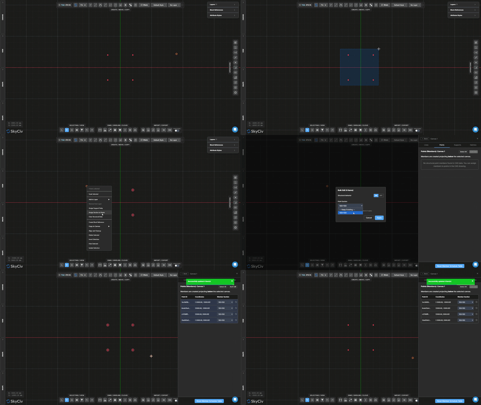
Assigning Sections to Points (Колонны)
Define points as structural columns
Structural data can be assigned to points so they are recognised as columns during export.
STEP-BY-STEP
Highlight the required points.
Right-click the selected points.
Выбрать Assign Sections to Points.
Давать возможность Structural Data.
Apply the required section.
Заметка:Points assigned structural sections will be exported as columns. Columns are generated projecting below the selected canvas, allowing them to connect between elevations in multi-canvas models.
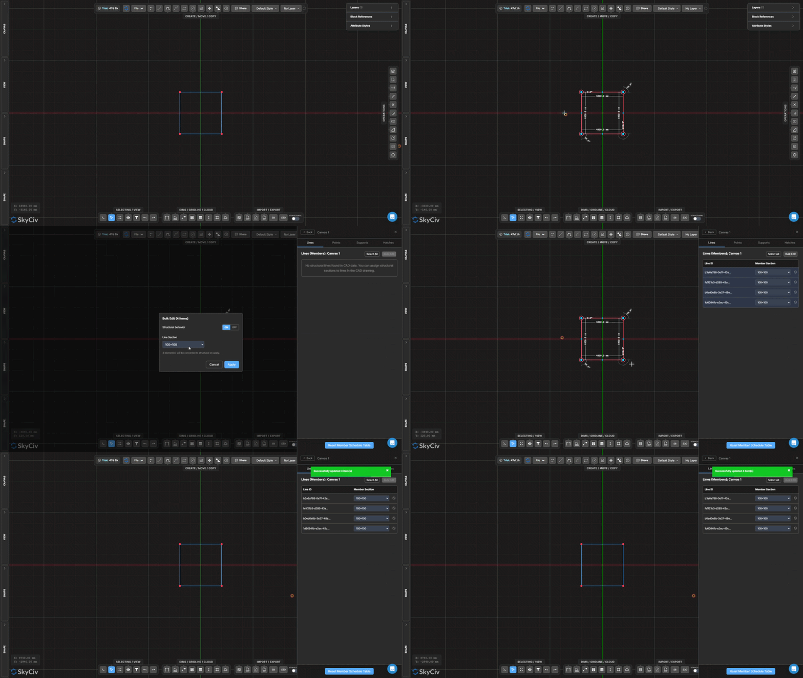
Assigning Sections to Lines (Балки)
Define lines as structural beam members
Structural data can be assigned to lines so they are recognised as beams during export.
STEP-BY-STEP
Select the required lines.
Щелкните правой кнопкой мыши.
Выбрать Assign Sections to Lines.
Давать возможность Structural Behaviour.
Apply the required section.
Заметка:Lines assigned structural sections will be exported as beam members in S3D.
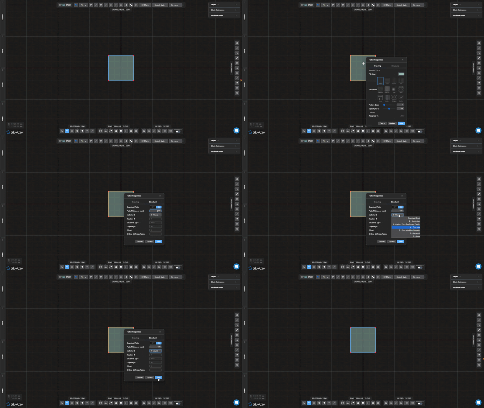
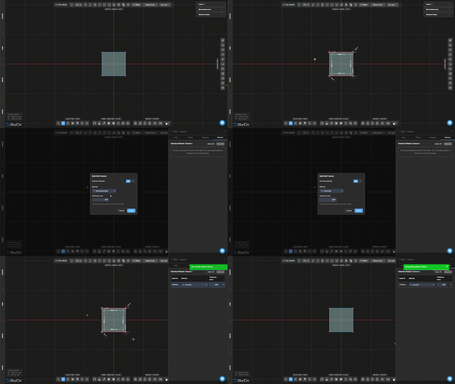
Assigning Plate Properties
Define hatch regions as structural plates, плиты, или стены
Hatch regions are referred to as plates because they represent surface-based structural elements such as slabs and walls.
STEP-BY-STEP
Select the required hatch regions.
Щелкните правой кнопкой мыши.
Выбрать Assign Plate Properties.
Давать возможность Structural Behaviour.
Select a material.
Enter a plate thickness.
Заметка:Plate properties can be modified at any time by double-clicking an existing hatch region and selecting theструктурная вкладка.
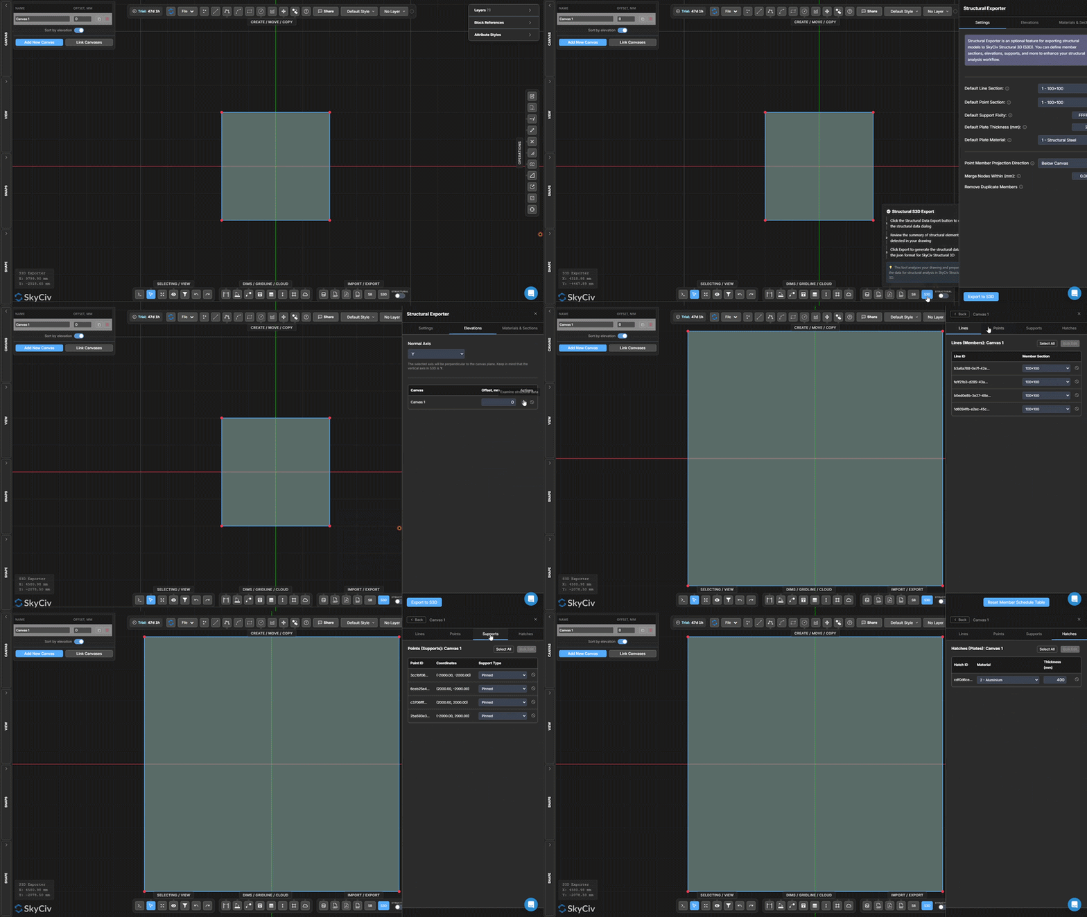
Reviewing Structural Data
Verify structural information before exporting to S3D
Before exporting to S3D, it is recommended to review all assigned structural data to ensure the model has been configured correctly.
STEP-BY-STEP
неподвижная точка в пространстве, которая не движется S3Dbutton in the bottom-right corner of the screen.
Перейдите к Высоты вкладка.
неподвижная точка в пространстве, которая не движется Examine Structural Data кнопка (magnifying glass icon).
AVAILABLE DATA TABLES
Structural Object
Information Displayed
опоры
Assigned support fixities
Колонны
Assigned sections
Балки
Assigned sections
Тарелки
Material and thickness information
Заметка:Selecting an item within any structural data table will automatically highlight the corresponding member on the canvas, making it easy to locate and review specific objects.
Best Practice:Reviewing structural data before exporting is the quickest way to identify missing supports, incorrect sections, or incomplete plate properties and ensure the model is ready for export.
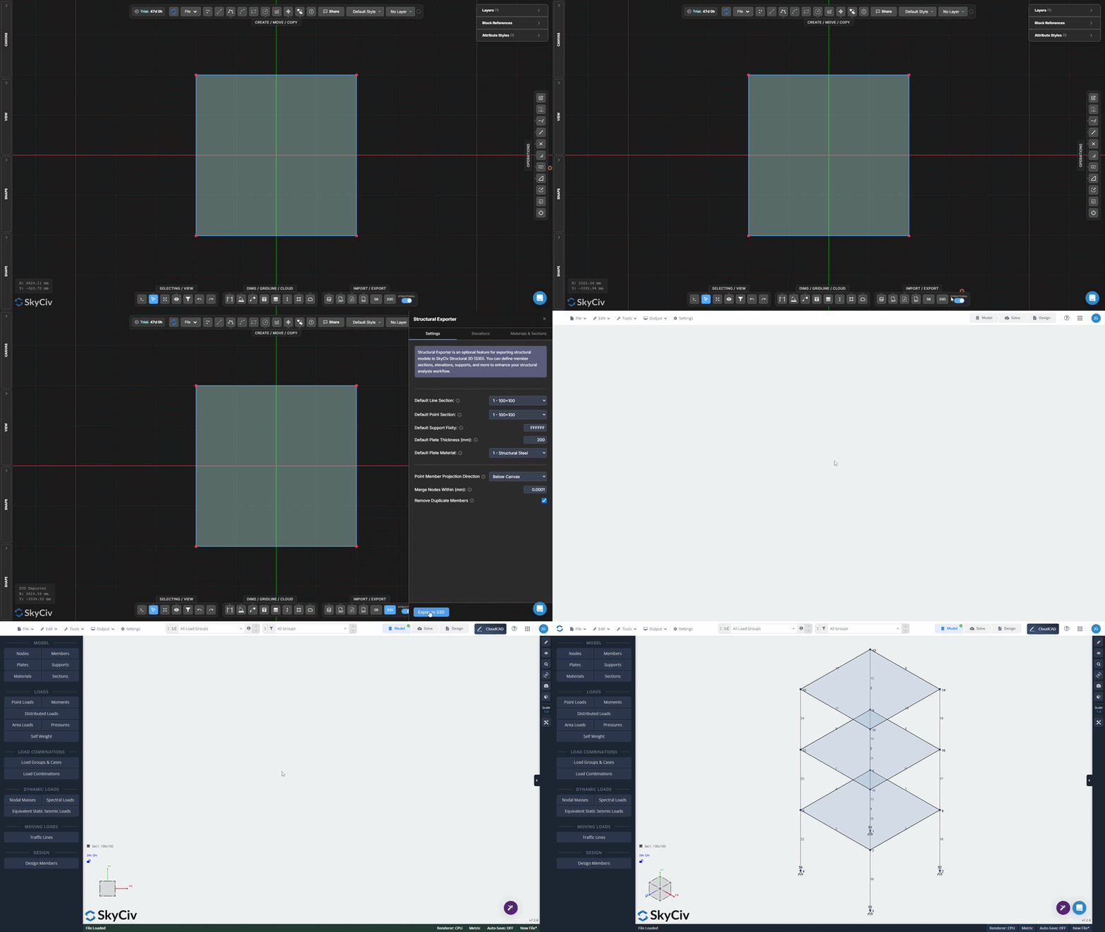
Exporting to S3D
Transfer your structural model directly into S3D
Once all structural data has been assigned and reviewed, the model is ready to be exported to S3D for loading, анализ, и дизайн.
STEP-BY-STEP
Откройте Structural Exporter.
Review the export settings.
Select the appropriateNormal Axis (Икс, И, или С УЧАСТИЕМ).
Выбрать Экспорт в S3D.
Заметка:The Normal Axis defines the vertical direction of the exported model. Ensure the correct axis is selected before exporting.
What Happens Next?After export, the model will open in S3D where loads, сочетания нагрузок, analysis settings, and design checks can be applied.
Пример работы
The following example demonstrates the complete workflow for creating a multi-level structural model in CloudCAD and exporting it directly to S3D
Starting with simple drafting geometry, we will create multiple levels using the Master and Child Canvas system, assign structural data, review the generated model and export it for structural analysis.
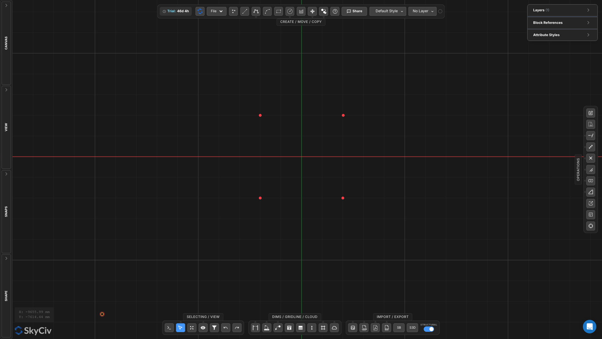
шаг 1 – Create Ground Floor Column Locations
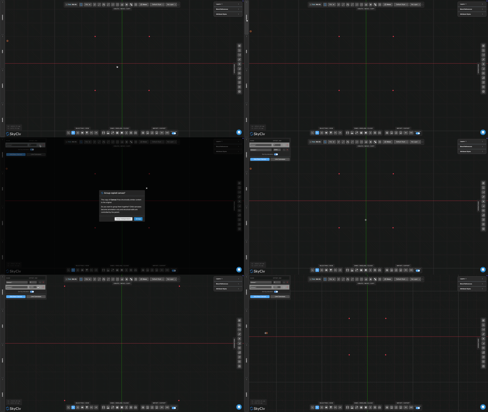
Begin by creating four points on Canvas 1.
These points represent the column locations for the structure.
At this stage no structural data has been assigned. The points simply define where columns will eventually be projected from the above canvas.
шаг 2 – Create the First Floor Canvas
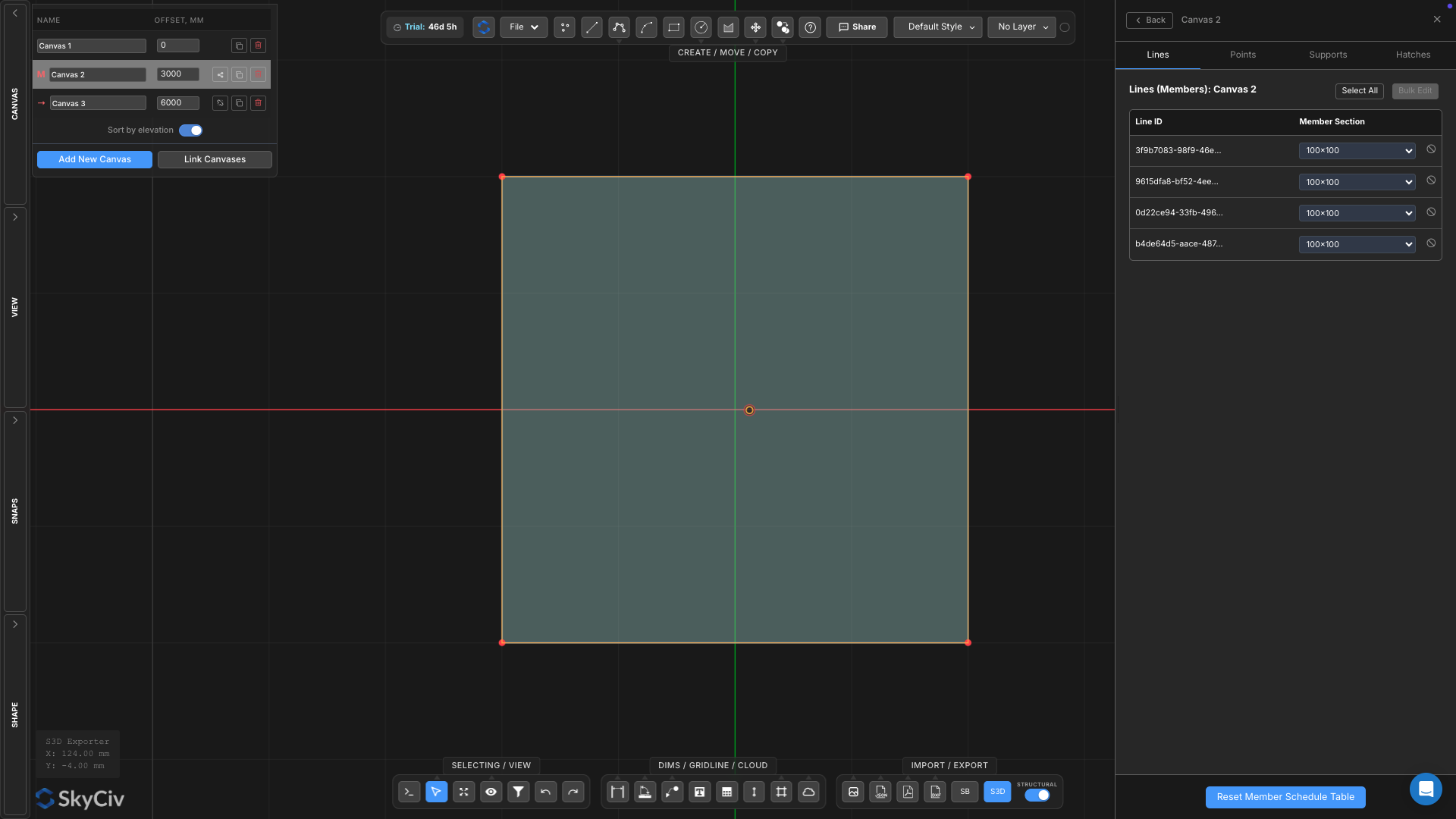
To create the first floor level, duplicate Canvas 1.
Duplicating the canvas copies the existing geometry, ensuring the column locations remain aligned between levels.
When prompted, выбирать Keep Independentrather than creating a canvas group.
The duplicated canvas can now contain different geometry from the original canvas. This is important because grouped canvases share structural geometry, making them unsuitable when each level requires a different structural layout.
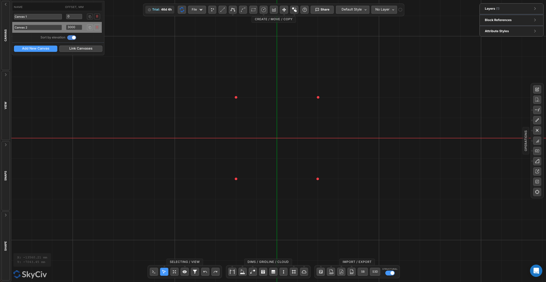
At this stage:
Canvas 1 contains the ground floor column locations.
Canvas 2 contains matching column locations at the first floor level.
Both canvases remain independent and can be modified separately.
This sets up the next step where you draw the beam and plate geometry on Canvas 2.
шаг 3 – Create the Floor Framing Layout
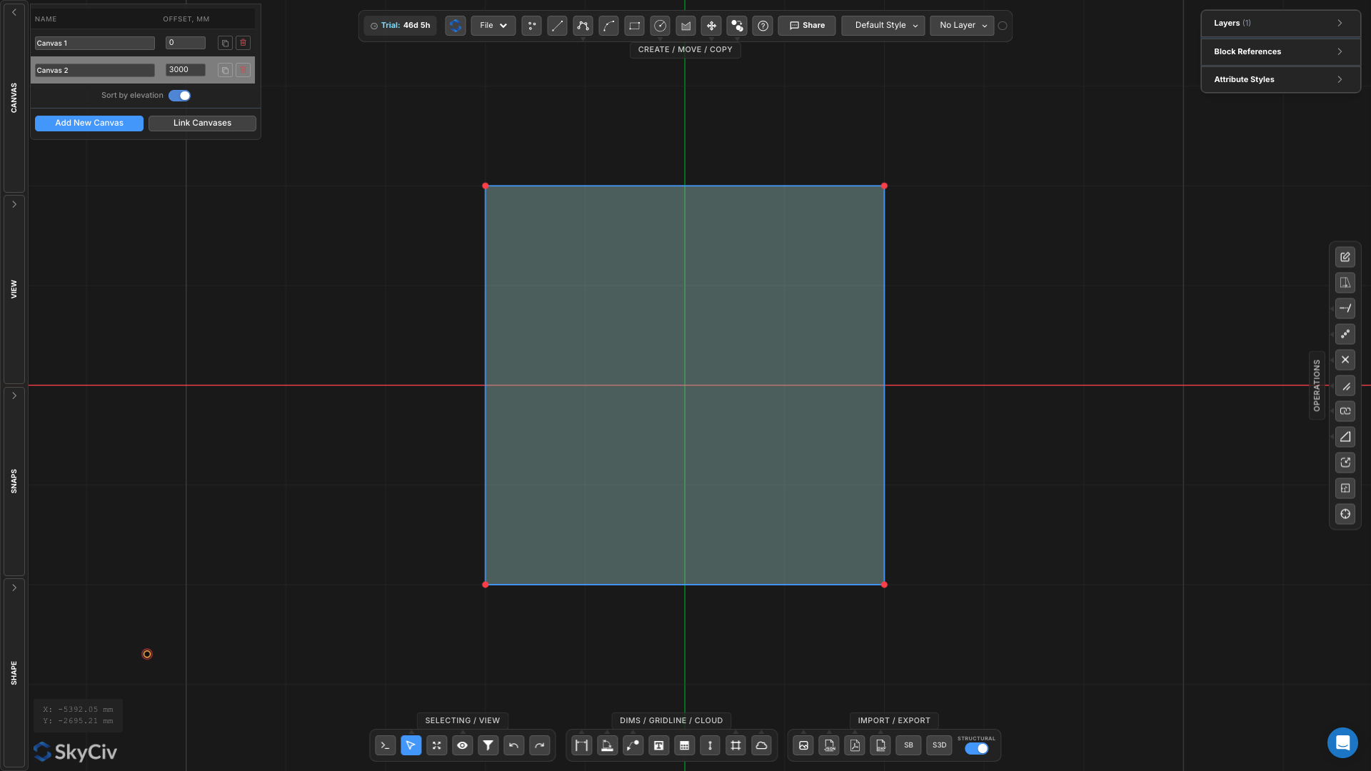
On Canvas 2:
Draw perimeter beam lines connecting the column locations
Create a hatch region representing the floor slab
шаг 4 – Create a Master and Child Canvas Group
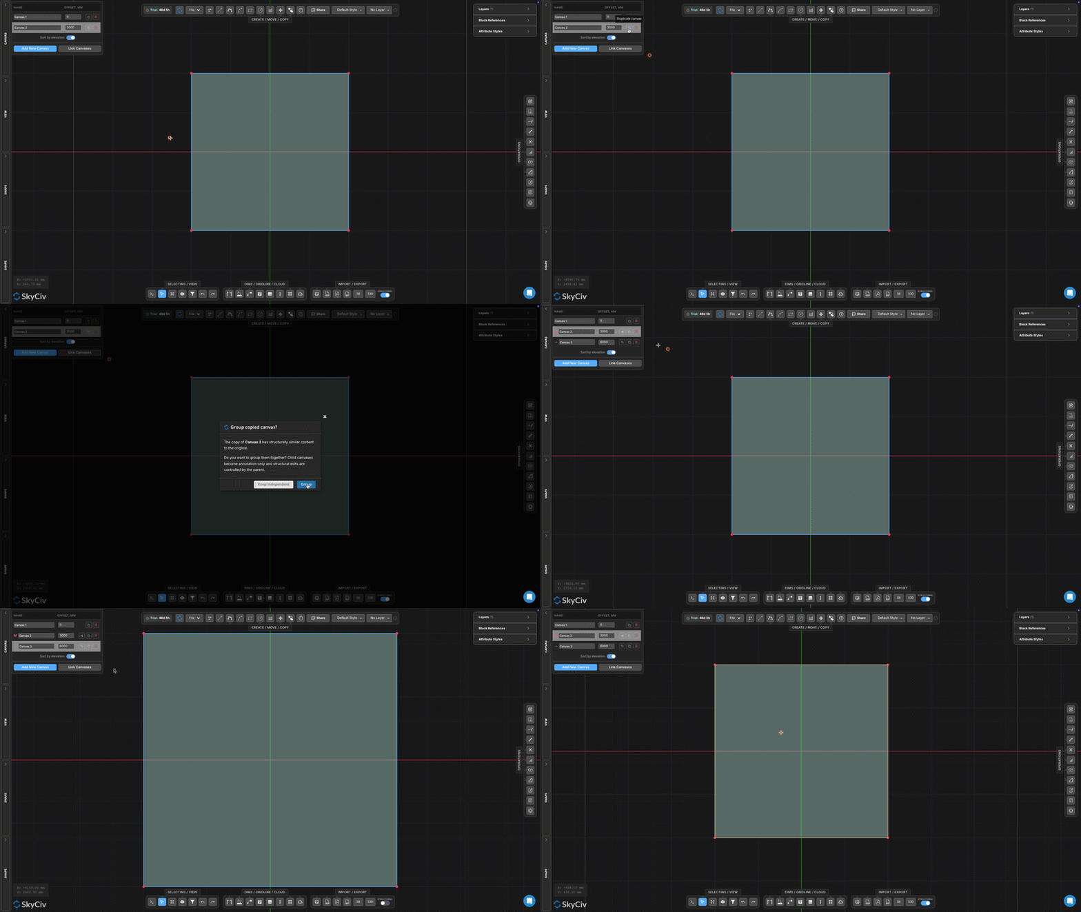
Duplicate Canvas 2 to create a third canvas.
When prompted, выбирать Group Canvas.
Canvas 2 will become theMaster Canvasand Canvas 3 will become aChild Canvas.
The Child Canvas automatically inherits the structural geometry and structural data assigned to the Master Canvas. Any structural changes made to the Master Canvas can be propagated to all linked Child Canvases, making this workflow ideal for repeated floor layouts in multi-storey structures.
В этом примере, the same beam and plate layout will be used on both elevated levels, allowing the structure to be modelled once and reused across multiple floors.
шаг 5 – Assign Structural Data to Master
With Geometry complete, structural properties can be applied
Press commandАto select all geometry on the Master Canvas.
Right-click and selectAssign Sections to Points.
Apply the default structural section.
Right-click and selectAssign Sections to Lines.
Apply the default structural section.
Select the hatch region.
Right-click and selectAssign Plate Properties.
Set the material toбетон.
Enter a plate thickness of300 мм.
Because Canvas 3 is linked as a Child Canvas, all structural geometry and assigned properties are automatically inherited from the Master Canvas. This allows repeated floor layouts to be managed from a single location while maintaining consistent structural data across multiple levels.
шаг 6 – Assign Supports
Return to Canvas 1 and assign supports to the column locations.
Select all column points
Щелкните правой кнопкой мыши
Выбрать Assign Support Fixity
Выбирать Зафиксированный
Columns exported from the upper levels will project down to these support locations.
шаг 7 – Review Structural Data
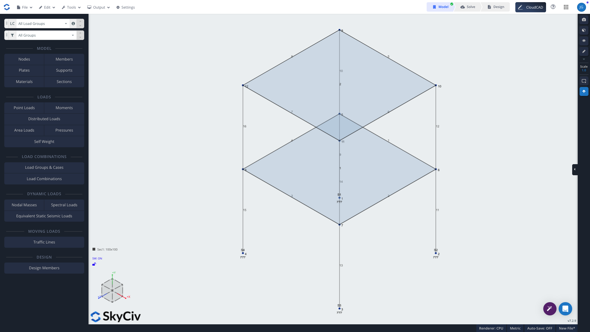
Before exporting, review the generated structural model.