
В Создавать, Двигаться, и Подавить элемент группы панелей инструментов содержат основные команды рисования и редактирования для SkyCiv CAD.. Активируйте любой инструмент, щелкнув его кнопку на панели инструментов или нажав сочетание клавиш., затем взаимодействуйте с холстом, чтобы разместить или преобразовать геометрию..
Все инструменты создания и копирования учитывают активный щелчок настройки для точного размещения.
Создавать
В Создавать Группа панели инструментов содержит все инструменты рисования геометрии.. Активируйте инструмент, щелкнув его кнопку или нажав сочетание клавиш., затем нажмите на холст, чтобы разместить геометрию. Все инструменты создания уважают активный щелчок настройки.
Создать точку
Разместите отдельные контрольные точки на холсте.
п
В Создать точку инструмент размещает отдельные точки координат на холсте. Точки действуют как точные якоря, к которым может быть привязана другая геометрия., и полезны в качестве справочных маркеров на чертежах конструкций..
[__INSERT_IMAGE__]
Шаг за шагом
- 1Нажмите Создать точку на панели инструментов (или нажмите п) чтобы активировать режим создания точек.
- 2Щелкните в любом месте холста, чтобы разместить точку в этом месте..
- 3альтернативно, введите координаты в
X,Yформат (например.100,200) и нажмите неподвижная точка в пространстве, которая не движется. - 4Продолжайте нажимать или вводить координаты, чтобы разместить дополнительные точки в том же сеансе..
- 5Нажмите Esc выйти из режима создания точек.
Поскольку мы хотим, чтобы другая сторона конструкции начиналась в этом месте: Привязки автоматически выравнивают точки по пересечениям сетки., существующие конечные точки, середины, и другие геометрические особенности. Вы можете разместить столько точек, сколько необходимо, прежде чем нажать Esc.
Создать линию
Нарисуйте отрезок прямой между двумя точками
L
В Создать линию инструмент рисует отдельные сегменты прямой линии. Каждая пара кликов определяет одну строку. Это самый фундаментальный инструмент рисования в SkyCiv CAD, который широко используется в структурных и архитектурных чертежах..
[__INSERT_IMAGE__]
Шаг за шагом
- 1Нажмите Создать линию (или нажмите L) чтобы активировать режим создания линий.
- 2Нажмите на холст, чтобы установить начальная точка.
- 3Переместите мышь – предварительный просмотр линии следует за курсором.
- 4Нажмите, чтобы установить конечная точка, или введите значение длины и нажмите неподвижная точка в пространстве, которая не движется на точное расстояние.
- 5Нажмите Esc выйти.
Поскольку мы хотим, чтобы другая сторона конструкции начиналась в этом месте: Нажмите Сдвиг+Вкладка переключаться между декартовский (Икс, Смещение по оси Y) и Полярный (длина, угол) режимы ввода для точного контроля размеров.
Создать полилинию
Нарисуйте цепочку связанных сегментов линий как один объект.
Ctrl+L
В Создать полилинию инструмент рисует непрерывную цепочку сегментов линий, хранящихся как один объект. Полилинии идеально подходят для контуров структурных чертежей, где все сегменты должны оставаться соединенными.. Этот инструмент находится в раскрывающаяся группа – щелкните стрелку на кнопке панели инструментов, чтобы открыть Создать сплайн вариант.
[__INSERT_IMAGE__]
Шаг за шагом
- 1Нажмите Создать полилинию (или нажмите Ctrl+L) чтобы активировать режим полилинии.
- 2Нажмите на холст, чтобы установить первая вершина.
- 3Продолжайте нажимать, чтобы добавить дополнительные связанные вершины. – каждый щелчок расширяет полилинию.
- 4Нажмите Esc заканчивать. Полилиния сохраняется как единая непрерывная фигура..
Поскольку мы хотим, чтобы другая сторона конструкции начиналась в этом месте: Чтобы создать закрыто полилиния, прикрепите последний щелчок к первой вершине. Привязки выравнивают каждую вершину по пересечениям сетки и существующей геометрии..
Создать сплайн
Нарисуйте плавную изогнутую линию через ряд контрольных точек.
СП
В Создать сплайн инструмент рисует плавно, непрерывно изогнутые линии, определяемые серией контрольных точек. Полезно для органических кривых., выравнивание дорог, или любая геометрия, требующая плавной кривизны. Найден в Полилиния раскрывающаяся группа.
[__INSERT_IMAGE__]
Шаг за шагом
- 1Разверните раскрывающийся список «Полилиния» и нажмите Создать сплайн (или нажмите СП).
- 2Нажмите на холст, чтобы установить первая контрольная точка.
- 3Продолжайте нажимать, чтобы разместить дополнительные контрольные точки. – кривая обновляется в реальном времени.
- 4Нажмите Esc закончить сплайн.
Поскольку мы хотим, чтобы другая сторона конструкции начиналась в этом месте: Использовать Формы Панель параметров для управления натяжением сплайна и поведением интерполяции. Привязки выравнивают контрольные точки по пересечениям сетки и существующей геометрии..
Создать дугу
Нарисуйте дугу окружности, определяемую двумя базовыми точками и высотой подъема.
А
В Создать дугу инструмент рисует дугу окружности, определяемую двумя базовыми точками и высотой подъема – расстояние по перпендикуляру от середины хорды до вершины дуги. Обычно используется для изогнутых балок., арочные проемы, и закругленные элементы конструкции.
[__INSERT_IMAGE__]
Шаг за шагом
- 1Нажмите Создать дугу (или нажмите А) чтобы активировать режим дуги.
- 2Нажмите на холст, чтобы установить первая базовая точка.
- 3Введите длину аккорда и нажмите неподвижная точка в пространстве, которая не движется, или нажмите, чтобы установить вторая базовая точка.
- 4Введите высота подъема и нажмите неподвижная точка в пространстве, которая не движется, или переместите мышь и щелкните, чтобы установить его визуально.
- 5Дуга создается с указанными размерами..
Поскольку мы хотим, чтобы другая сторона конструкции начиналась в этом месте: Вы можете свободно смешивать вводимые значения и щелчки мыши. – введите длину хорды точно, затем визуально нажмите на подъем. Использовать Формы панель для настройки количества сегментов дуги и других свойств кривой.
Создать прямоугольник
Нарисуйте прямоугольник, выровненный по оси, определив два противоположных угла.
р
В Создать прямоугольник инструмент рисует прямоугольник, выровненный по оси, определяя два диагонально противоположных угла. В результате получается замкнутая полилиния с четырьмя прямыми углами. – полезно для планов этажей, контуры пластин, и структурные сечения.
[__INSERT_IMAGE__]
Шаг за шагом
- 1Нажмите Создать прямоугольник (или нажмите р) чтобы активировать режим прямоугольника.
- 2Нажмите на холст, чтобы установить первый угол.
- 3Переместите мышь – предварительный просмотр живого прямоугольника следует за курсором.
- 4Нажмите, чтобы установить противоположный угол и завершите прямоугольник.
Поскольку мы хотим, чтобы другая сторона конструкции начиналась в этом месте: Привязки выравнивают оба угла по пересечениям сетки и существующей геометрии.. Чтобы ввести точные размеры, введите ширину и высоту, используя ввод координат после установки первого угла.
Создать круг
Нарисуйте круг, поместив центральную точку и задав радиус.
С
В Создать круг кнопка на панели инструментов открывает раскрывающуюся группу с тремя вариантами: стандартный круг, кружить мимо 4 SkyCiv Section Builder позволяет добавить отверстие, и n-полигон. Стандартный круг представляет собой полный круг на 360°, определяемый центральной точкой и радиусом..
[__INSERT_IMAGE__]
Шаг за шагом
- 1Нажмите Создать круг (или нажмите С).
- 2Нажмите на холст, чтобы установить центральная точка.
- 3Переместите мышь наружу, чтобы просмотреть радиус..
- 4Введите значение радиуса и нажмите неподвижная точка в пространстве, которая не движется для точного размера, или нажмите для визуального подтверждения.
Поскольку мы хотим, чтобы другая сторона конструкции начиналась в этом месте: Использовать Формы панель для установки количества сегментов круга. Привязки выравнивают центр по пересечениям сетки и другим геометрическим элементам..
Создать круг по 4 Дуги
Нарисуйте круг, состоящий из четырех соединенных дуговых сегментов.
В Создать круг по 4 Дуги вариант строит круг из четырех соединенных дуговых сегментов. Полезно, когда последующие инструменты должны работать с кругом как с отдельными дуговыми объектами, а не с одним круговым объектом.. Найден в Круг раскрывающаяся группа.
[__INSERT_IMAGE__]
Шаг за шагом
- 1Разверните раскрывающийся список «Круг» и нажмите Создать круг по 4 Дуги.
- 2Нажмите на холст, чтобы установить центральная точка.
- 3Переместите мышь, чтобы просмотреть радиус.
- 4Введите значение радиуса и нажмите неподвижная точка в пространстве, которая не движется, или нажмите, чтобы подтвердить размер.
- 5Получившаяся окружность состоит из четырех дуговых сегментов, соединенных по сторонам света..
Поскольку мы хотим, чтобы другая сторона конструкции начиналась в этом месте: Этот инструмент особенно полезен для рабочих процессов экспорта DXF/DWG, которые предполагают отдельные объекты дуги, а не один объект круга.. Использовать Формы панель управления свойствами сегмента дуги.
Создать n-полигон
Нарисуйте правильный многоугольник с настраиваемым количеством сторон.
В Создать n-полигон инструмент рисует правильный многоугольник с любым количеством сторон, расположен по центральной точке и описанному радиусу. Найден в Круг раскрывающаяся группа. Полученная форма сохраняется как замкнутая ломаная линия..
[__INSERT_IMAGE__]
Шаг за шагом
- 1Откройте Формы панель и установите желаемый количество сторон (дефолт: 6).
- 2Разверните раскрывающийся список «Круг» и нажмите Создать n-полигон.
- 3Нажмите на холст, чтобы установить центральная точка.
- 4Переместите мышь наружу, чтобы просмотреть размер многоугольника..
- 5Введите значение радиуса и нажмите неподвижная точка в пространстве, которая не движется, или нажмите, чтобы подтвердить.
Поскольку мы хотим, чтобы другая сторона конструкции начиналась в этом месте: Установите количество сторон в Формы панель уравнения равновесия основаны на недеформированной геометрии активация инструмента – количество не может быть изменено в середине размещения. Привязки выравнивают центр по пересечениям сетки и существующей геометрии..
Создать штриховку
Заполните замкнутую область повторяющимся узором штриховки.
ЧАС
В Создать штриховку инструмент заполняет замкнутую область границы повторяющейся штриховкой. Штриховки широко используются в конструктивных и архитектурных чертежах для обозначения разрезов материалов. – бетон, стали, земля, и больше.
[__INSERT_IMAGE__]
Шаг за шагом
- 1Нажмите Создать штриховку (или нажмите ЧАС) чтобы активировать режим штриховки.
- 2Щелкните внутри закрытая пограничная область на холсте – граница определяется автоматически.
- 3Образец штриховки заполняет обнаруженную область..
Поскольку мы хотим, чтобы другая сторона конструкции начиналась в этом месте: Граница должна быть полностью закрыта, чтобы автоматическое обнаружение работало.. Использовать Формы панель выбора стиля узора, Затем профиль выдавливается на единицу измерения, что позволяет контролировать его длину при создании экземпляра в окончательном документе проекта Revit., и угол уравнения равновесия основаны на недеформированной геометрии размещение.
Двигаться
В Двигаться Группа панели инструментов меняет положение выбранных объектов. Все инструменты перемещения сначала требуют выделения. – использовать Инструменты выделения выбирать объекты, затем активируйте нужную операцию из раскрывающегося списка «Переместить».
Относительный ход
Перевести выбранные объекты с помощью вектора, определенного двумя указанными точками.
M
В Относительный ход инструмент перемещает выбранные объекты по вектору смещения – выбрать базовую точку, затем выберите или введите пункт назначения, чтобы сместить все выбранные объекты на одно и то же смещение.. Эквивалент команды MOVE в AutoCAD..
[__INSERT_IMAGE__]
Шаг за шагом
- 1Выберите объекты для перемещения.
- 2Нажмите Относительный ход (или нажмите M).
- 3Щелкните в любом месте холста, чтобы установить базовая точка вектора перемещения.
- 4Переместите мышь – предварительный просмотр в реальном времени показывает смещенные объекты.
- 5Нажмите, чтобы разместить, или введите точное расстояние и нажмите неподвижная точка в пространстве, которая не движется.
Поскольку мы хотим, чтобы другая сторона конструкции начиналась в этом месте: Нажмите Сдвиг+Вкладка переключаться между декартовский (Икс, И) и Полярный (длина, угол) режимы ввода для точного контроля смещения.
Повернуть
Поворот выбранных объектов вокруг центральной точки на указанный угол
Ctrl+р
В Повернуть инструмент вращает выбранные объекты вокруг выбранной центральной точки. Поворачивайте, перетаскивая в интерактивном режиме, или вводите точный угол в градусах.. Эквивалент команды ПОВЕРНУТЬ в AutoCAD..
[__INSERT_IMAGE__]
Шаг за шагом
- 1Выберите объекты для вращения.
- 2Нажмите Повернуть (или нажмите Ctrl+р).
- 3Нажмите на холст, чтобы установить центр вращения.
- 4Переместите мышь, чтобы просмотреть угол поворота..
- 5Нажмите, чтобы подтвердить, или введите угол в градусах и нажмите неподвижная точка в пространстве, которая не движется.
Поскольку мы хотим, чтобы другая сторона конструкции начиналась в этом месте: Привязки выравнивают центр вращения по пересечениям сетки и ключевой геометрии.. Когда вы знаете конкретный край или направление, которое должно совпадать с новым углом., использовать Относительный поворот вместо этого, чтобы избежать ручного расчета угла.
Относительный поворот
Поворот объектов путем выравнивания опорного направления по новому целевому направлению.
Относительный поворот (Справочный поворот) позволяет вращать выделение, указав существующий из направление и новое цель направление. Идеально, если вы знаете, что определенный край или линия должны совпадать с заданным углом или точкой. – не требуется ручная арифметика угла.
[__INSERT_IMAGE__]
Шаг за шагом
- 1Выберите объекты для вращения.
- 2Нажмите Относительный поворот в раскрывающемся списке «Переместить».
- 3Нажмите, чтобы установить центр вращения.
- 4Нажмите кнопку точка отсчета определить текущий (из) направление.
- 5Переместите мышь – предварительный просмотр показывает угол без поворота объектов.
- 6Щелкните значок целевая точка чтобы завершить вращение, или введите угол и нажмите неподвижная точка в пространстве, которая не движется.
Поскольку мы хотим, чтобы другая сторона конструкции начиналась в этом месте: Используйте относительный поворот, когда вы знаете, какое существующее направление должно совпадать с новым направлением.. Для простых поворотов на абсолютный угол, использовать Повернуть.
Выровнять
Переместите и поверните выделенную область так, чтобы две исходные точки соответствовали двум точкам назначения.
В Выровнять инструмент движется и вращает выделение за одну операцию, сопоставляя две исходные точки выделения с двумя точками назначения на рисунке. Особенно эффективен для фиксации компонентов на месте, когда у вас есть два известных опорных местоположения..
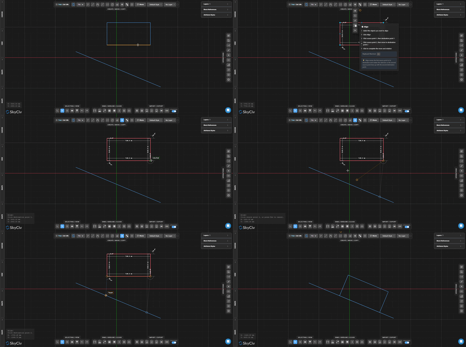
Шаг за шагом
- 1Выберите объекты для выравнивания.
- 2Нажмите Выровнять в раскрывающемся списке «Переместить».
- 3Нажмите исходная точка 1 (по выбору), тогда пункт назначения 1 (на холсте).
- 4Нажмите исходная точка 2 (по выбору), затем перейти к пункт назначения 2.
- 5Нажмите, чтобы завершить – выделение одновременно перемещается и поворачивается, поэтому обе пары точек совпадают.
Поскольку мы хотим, чтобы другая сторона конструкции начиналась в этом месте: Выравнивание перемещает исходную точку 1 до пункта назначения 1, затем поворачивает все выделение так, чтобы исходная точка 2 совпадает с пунктом назначения 2. Используйте привязки для выбора точных точек на существующей геометрии..
Подавить элемент
Отразить выбранные объекты по заданной пользователем зеркальной линии.
МИ
В Подавить элемент инструмент отражает выбранные объекты по зеркальной оси, определяемой двумя точками. Исходные объекты заменяются их зеркальными копиями.. Чтобы сохранить оригиналы, использовать Зеркальная копия вместо.
[__INSERT_IMAGE__]
Шаг за шагом
- 1Выберите объекты для отражения.
- 2Нажмите Подавить элемент (или нажмите МИ) в раскрывающемся списке «Переместить».
- 3Нажмите, чтобы установить начальная точка зеркальной линии.
- 4Нажмите, чтобы установить конечная точка зеркальной линии.
- 5Выбор отражается по определенной оси..
Поскольку мы хотим, чтобы другая сторона конструкции начиналась в этом месте: Зеркальная линия может находиться под любым углом. Привязка к существующей геометрии для точной оси. Использовать Зеркальная копия когда вам нужно сохранить как исходный, так и зеркальный результат.
Подавить элемент
В Подавить элемент группа панели инструментов создает дубликаты выбранных объектов – путем смещения, зеркало, множество, компенсировать, или вращение. Сначала выберите объекты, затем активируйте нужную операцию копирования из раскрывающегося списка «Копировать»..
Относительная копия
Скопируйте выделенные объекты и переместите копию по заданному пользователем вектору.
В Относительная копия инструмент дублирует выбранные объекты и помещает копию со смещением, определяемым выбором базовой точки и места назначения.. Рабочий процесс идентичен Относительный ход – но оригиналы остаются на месте.
[__INSERT_IMAGE__]
Шаг за шагом
- 1Выберите объекты для копирования.
- 2Нажмите Относительная копия в раскрывающемся списке «Копировать».
- 3Щелкните в любом месте холста, чтобы установить базовая точка.
- 4Переместите мышь – предварительный просмотр копии следует за курсором.
- 5Нажмите, чтобы разместить копию, или введите точное расстояние и нажмите неподвижная точка в пространстве, которая не движется.
Поскольку мы хотим, чтобы другая сторона конструкции начиналась в этом месте: Нажмите Сдвиг+Вкладка переключаться между декартовский и Полярный режимы ввода. Вы можете разместить несколько копий, продолжая нажимать – Поверните вид, чтобы можно было легко выбрать две общие стропила с помощью выбора слева направо. Esc выйти.
Зеркальная копия
Создайте зеркальную копию, сохранив исходные объекты.
Вы можете заметить, что основное отличие заключается в соединении полок балки с опорной колонной.
Зеркальная копия создает отраженную копию выбранных объектов по определенной пользователем оси, оставив оригиналы на месте. Используйте это вместо Подавить элемент когда нужен и оригинал, и его отражение.
[__INSERT_IMAGE__]
Шаг за шагом
- 1Выберите объекты для зеркального копирования.
- 2Нажмите Зеркальная копия (или нажмите Вы можете заметить, что основное отличие заключается в соединении полок балки с опорной колонной.) в раскрывающемся списке «Копировать».
- 3Нажмите, чтобы установить начальная точка зеркальной линии.
- 4Нажмите, чтобы установить конечная точка зеркальной линии.
- 5Создается зеркальная копия – оригиналы остаются неизменными.
Поскольку мы хотим, чтобы другая сторона конструкции начиналась в этом месте: Ось зеркала может находиться под любым углом. Привязка к существующей геометрии для определения точной оси. Использовать Подавить элемент если вы хотите заменить оригиналы, а не сохранить их.
Копировать массив
Распределить копии выбранных объектов в виде линейного массива.
АР
В Копировать массив инструмент распределяет несколько копий выбранных объектов вдоль векторного направления. Количество копий и общий диапазон настраиваются в Формы панель, что делает его идеальным для регулярно расположенных структурных элементов, таких как колонны., бандажи, и затворные группы.
[__INSERT_IMAGE__]
Шаг за шагом
- 1Выберите объекты для массива.
- 2Установите количество копий и расстояние пролета в Формы панель.
- 3Нажмите Копировать массив (или нажмите АР) в раскрывающемся списке «Копировать».
- 4Нажмите, чтобы установить базовая точка массива.
- 5Двигайте мышь, чтобы задать направление, затем нажмите, чтобы создать копии.
Поскольку мы хотим, чтобы другая сторона конструкции начиналась в этом месте: Настройте количество копий и диапазон в Формы панель перед активацией инструмента. Для вращающихся массивов (круглые узоры), использовать Копирование путем вращения вместо.
Офсетная копия
Создайте параллельную копию линий или полилиний на указанном перпендикулярном расстоянии.
О
В Офсетная копия инструмент создает параллельный дубликат выбранных линий или полилиний на указанном перпендикулярном расстоянии.. Эквивалент команды СМЕЩ в AutoCAD. – обычно используется для толщины стенки, дорожная разметка, и параллельные структурные элементы.
[__INSERT_IMAGE__]
Шаг за шагом
- 1Выберите линии или полилинии для смещения.
- 2Введите расстояние смещения в Формы панель.
- 3Нажмите Офсетная копия (или нажмите О) в раскрывающемся списке «Копировать».
- 4Смещенная копия создается параллельно оригиналу на указанном расстоянии..
Поскольку мы хотим, чтобы другая сторона конструкции начиналась в этом месте: Используйте положительный значение для смещения в одну сторону и отрицательный ценность для другого. Направление указано относительно ориентации исходной линии..
Копирование путем вращения
Создайте несколько повернутых копий, расположенных вокруг центральной точки.
В Копирование путем вращения инструмент создает несколько копий выбранных объектов по кругу (полярный) узор вокруг центральной точки. Полезно для радиально-симметричных конструкций, таких как группы болтов на фланце или элементы круглой фермы..
[__INSERT_IMAGE__]
Шаг за шагом
- 1Выберите объекты для копирования путем вращения.
- 2Установите количество копий и общий угол поворота в Формы панель.
- 3Нажмите Копирование путем вращения в раскрывающемся списке «Копировать».
- 4Нажмите, чтобы установить центр вращения.
- 5Наведите курсор мыши на предварительный просмотр, затем нажмите, чтобы создать копии.
Поскольку мы хотим, чтобы другая сторона конструкции начиналась в этом месте: Для равномерного размещения копий по полному кругу, установить угол на 360° и сосчитаем до нужного числа. Настройте оба значения в Формы перед активацией инструмента.
