В этой статье, Мы разработаем пример дизайна плиты, используя последнюю версию ACI-318-19: “Требования Строительных норм для конструкционного бетона,” Состоящий из моделирования в Skyciv из железобетонного малоэтажного здания, сосредоточенного на сравнении результатов программного обеспечения и расчетов рук с помощью принятого метода ACI: “Метод прямого расчета плит.” Эта процедура состоит в том, чтобы назначить различные полосы вдоль основных направлений и рам.
Мы надеемся, что вы прочитали предыдущую статью, Проектирование пластин в S3D, Чтобы представиться в моделировании и проектировании тарелок с использованием Skyciv. Еще одна полезная информация, которую мы предлагаем, найдены в Как моделировать тарелки? После того, как вы закончите читать оба документа, Не стесняйтесь погрузиться в следующий пример сравнения с полной работой!
Общая планировка здания
На следующих изображениях показан изометрический вид и размеры в плане примера для расчета.. Здание имеет две приподнятые плоские плиты без балок между опорами колонн..
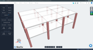
фигура 1. Пример изометрического вида здания
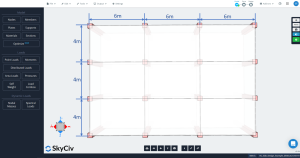
фигура 2. Размеры плана перекрытия
Прямой метод расчета двусторонних плит (ДДМ)
Ограничения
Аси 318 позволяет использовать МДМ для расчета железобетонных плит на гравитационные нагрузки, которые собирают некоторые реквизиты в соответствии с геометрией, отношения нагрузки, симметрия, и т.д. Мы можем суммировать эти ограничения в следующем списке (Примечания PCA):
- “В каждом направлении должно быть не менее трех непрерывных пролетов.”: фигура 2 показывает три пролета в каждом основном направлении, продольный и поперечный. Ok!
- “Панели перекрытий должны быть прямоугольными с соотношением большего пролета к меньшему. (осевая линия к осевой линии опор) не больше 2.”: В соответствии с рисунком 2, Соотношение равно \({\гидроразрыва{л_1}{4}= Гидроразрыва{6м}{4м}= 1,5 < 2}\). Ok!
- “Последовательные длины пролетов (осевая линия к осевой линии опор) в каждом направлении не должны отличаться более чем 1/3 из более длинного пролета”. Длина пролета одинакова в каждом направлении, 6м до продольного и 4 м к поперечному. Ok!
- “Столбцы не должны быть смещены более чем 10% пролета (в направлении смещения) от любой оси между центральными линиями последовательных столбцов”. Пример здания не имеет смещений в столбцах. Ok!
- “Нагрузки должны быть распределены равномерно, с нефакторизованной или эксплуатационной постоянной нагрузкой не более чем в два раза превышающей нефакторизованную или эксплуатационную стационарную нагрузку (Д/Д ≤ 2)”. Принимая значения каждой гравитационной нагрузки, соотношение определяется как \({\гидроразрыва{L}{D}= Гидроразрыва{2}{7.8}= 0,256 < 2}\). Ok!.
- “Для двусторонних балочных перекрытий, относительная жесткость балок в двух перпендикулярных направлениях должна удовлетворять минимальным и максимальным требованиям, указанным в нормах.” Уже удовлетворен; В плитах нет лучей.. Ok!
- “Перераспределение негативных моментов по коду не допускается.” Из -за простоты примера, Не потребуется перераспределить негативные моменты в плитах. Ok!.
Определение продольных и поперечных полос
Плита в DDM должна быть разделена на две основные полосы для анализа и проектирования конкретной линейной сетки.: колонна и средние полосы. Ширина для полос столбцов - меньшая из \({\гидроразрыва {л_1}{4}}\) и \({\гидроразрыва{L_2}{4}}\), где \({л_1}\) Длина пролета вдоль линейной сетки и \({L_2}\) это поперечная длина перпендикулярная.
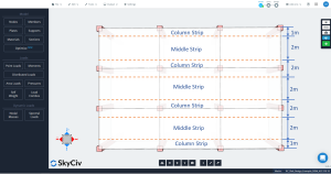
фигура 3. Продольная колонка и средние полосы.
![]()
фигура 4. Поперечная колонка и средние полосы.
Минимальная толщина
ACI-318 предлагает использовать уравнение: \({т_{мин}}знак равно {\гидроразрыва{l_n}{30}}знак равно{\гидроразрыва{6м-0.50м}{30}}=0.1833m = 0.20m\)
Предварительная проверка прочности сдвига
Перед расчетом стальной арматурной арматуры, Рекомендуется проверить сдвигу емкости плиты, Один для прямого сдвига в подключении, а другой для путающей сдвижной емкости на столбце подключаемой плиты.
Рассчитать спрос на сдвиг, Мы используем следующие гравитационные нагрузки:
- Самосветная плита: \({ПО={\гамма_с}\раз {т_{плита}}знак равно{24 {\гидроразрыва{кН}{м^3}}}\раз {0.20м}=4,8{\гидроразрыва{кН}{м^2}} }\)
- Наложенная статическая нагрузка: \({SD={3 {\гидроразрыва{кН}{м^2}}}}\)
- Общая мертвая нагрузка (ПО+SD): \({D = {7.8 {\гидроразрыва{кН}{м^2}}}}\)
- Живая нагрузка (Жилая площадь) : \({Л={2 {\гидроразрыва{кН}{м^2}}}}\)
- Учетная силовая нагрузка (1.2Д+1,6л): \({д_{U}знак равно{12.56 {\гидроразрыва{кН}{м^2}}}}\)
Первая проверка сдвига - это “сдвиг луча” тип, где следующее изображение указывает область, которая должна быть рассмотрена для получения общего сдвига. Мы проверяем каждое направление, захватив более обширную территорию.
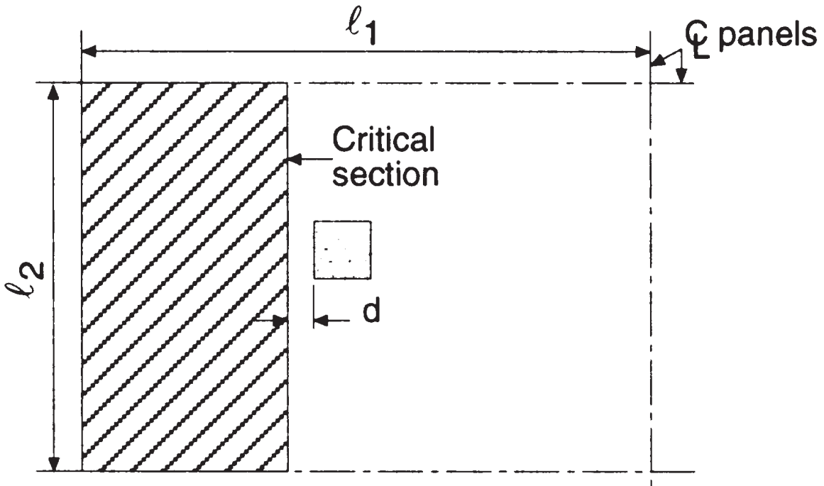
фигура 5. Сдвиг балки на внутренней колонне (Надим Хассунд и Актем Ай-Маназер, “Теория и дизайн конструкционного бетона”)
куда:
- Длины пролив в продольном направлении, \({L_1 = 6,0 м }\)
- Пролета длины в поперечном направлении, \({L_2 = 4,0 м}\)
- Общая зона притока, сдвиг в продольном направлении \({A_t = l_2 \times (\гидроразрыва{л_1}{2}-\гидроразрыва{C_1}{2}-d) = 4.0m \times (\гидроразрыва{6.0м}{2}-\гидроразрыва{0.50м}{2}-0.17м) знак равно 10.32 м^2}\) (выбранный)
- Общая зона притока, сдвиг в поперечном направлении, \({A_t = l_1 \times (\гидроразрыва{L_2}{2}-\гидроразрыва{C_2}{2}-d) = 6.0m \times (\гидроразрыва{4.0м}{2}-\гидроразрыва{0.50м}{2}-0.17м) знак равно 9.48 м^2}\)
- Квадратные столбцы измерение, \({C_1 = C_2 = 0,50 м}\)
- Расстояние d, \({d = h_{плита} – крышка = 0,20 м – 0.03М = 0,17 м }\)
Следовательно, максимальный сдвиг луча во внутренней колонке
\({V_u =q_u\times A_t =12.56 {\гидроразрыва{кН}{м^2}}\раз 10.32 m^2 = 129.62 кН }\)
Это будет сравниваться с сопротивлением сдвигу, \({\you_sv_c}\)
- Прочность бетона, \({f’_c = 25 МПа}\)
- Полученная арматурная прочность на сталь, \({f_y = 420 МПа}\)
- \({\phi_s = 0.75}\)
- \({\phi_sV_c = 0.17\phi_s \lambda \sqrt(f’_c) чб д; b_w = l_2}\)
\({\phi_sV_c = 0.17\times 0.75\times 1\times \sqrt(25 МПа) \раз 4000 mm\times 170 мм = 433.50 кН }\)
Мы видим, что сопротивление сдвига больше, чем спрос на сдвиг: \({\phi_sv_c = 433.50 кН > V_u = 129.62 кН }\) Ok!.
Согласно следующим изображениям, Мы должны вычислить грузоподъемность сдвига и силу, чтобы сопротивляться бетону во внутреннем соединении с кольцом с плитом. Намерение кода в проверке сдвига переноса состоит в том, чтобы поддерживать низкие значения напряжения сдвига.
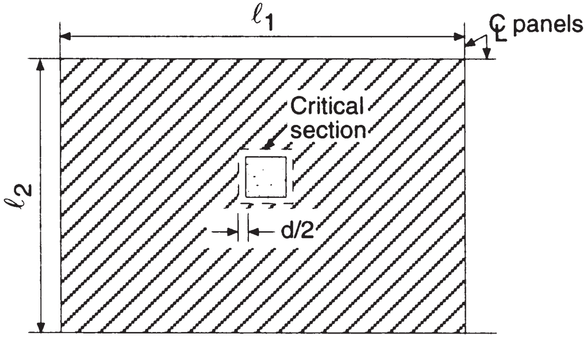
фигура 6. Двусторонний сдвиг на внутренней колонке (Надим Хассунд и Актем Ай-Маназер, “Теория и дизайн конструкционного бетона”)
- Общая зона притока, пробивные ножницы, \({A_t = l_1 \times l_2 – (C_1+D.)^2 = 6.0m \times 4.0m – (0.50М+0,17 м)^ 2 = 23.55 м^2}\) (Такая же область для обоих основных направлений)
Общая сила сдвига, подлежащая сопротивлению
\({V_u =q_u\times A_t =12.56 {\гидроразрыва{кН}{м^2}}\раз 23.55 m^2 = 295.79 кН }\)
Для получения перемешивания сдвига в двусторонней плите, Мы будем использовать эмпирический метод, созданный Code ACI-318, который учитывает максимальное напряжение сдвига, доступное по эффективному периметру в критическом разделе. Более консервативное выражение для интерьера
- Пробивание сдвиговой емкости, \({\phi_sV_c = 0.33\phi_s \lambda \sqrt(f’_c) b_0 d; b_0=4\times (C_1+D.)}\)
Следовательно, у нас есть сопротивление сдвига
\({\phi_sV_c = 0.33\times 0.75 \раз 1 \SQRT(25 МПа) \раз (4\раз (500 мм+170 мм)\раз 170 мм) знак равно 563.81 кН }\)
Мы видим, что сопротивление сдвига больше, чем спрос на сдвиг: \({\phi_sv_c = 563.81 кН > V_u = 295.75 кН }\) Ok!.
Мы проверили одно и двусторонние требования к сдвигу в соединении с колонкой интерьера. Из -за того, что оба требования меньше, чем их соответствующие возможности или сопротивления, Теперь мы переедем, чтобы рассчитать основное усиление арматуры для изгиба плиты.
Если вы новичок в SkyCiv, Зарегистрируйтесь и протестируйте программу самостоятельно!
Общий факторизованный статический момент за пролет.
Максимальный момент, который можно превратить в двойной фиксированный луч, является изостатический момент, равный \({M=ГРП{w\times {л_1}^ 2}{8}}\) (См. Рисунок 6).
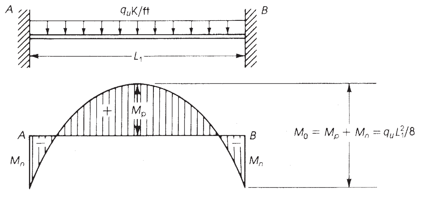
фигура 7. Изгибающий момент в фиксированном луче. (Надим Хассунд и Актем Ай-Маназер, “Теория и дизайн конструкционного бетона”)
ACI-18 принимает этот принцип и, Для метода прямого проектирования (ДДМ), устанавливает максимальный статический момент, который должен учитываться за промежуток \({M_0}\)
Продольное направление:
- \({M_0 = \frac {q_u\times l_2\times {l_{N,1}}^ 2}{8}}\)
- \({M_0 = \frac {12.56 {\гидроразрыва{кН}{м^2}}\times 4.0m\times (6м-0.50м)^ 2}{8}= 189,97 кн-м}\)
Поперечное направление:
- \({M_0 = \frac {q_u\times l_1\times {l_{N,2}}^ 2}{8}}\)
- \({M_0 = \frac {12.56 {\гидроразрыва{кН}{м^2}}\times 6.0m\times (4м-0.50м)^ 2}{8}= 115,40 кН-м}\)
Следующий шаг - назначить этот общий момент с учетом типа панели, интерьер или экстерьер. (См. Рисунок 7). После того, Из -за непрерывных пролетов, необходимо разделить также на момент положительного и отрицательного. Это последнее показано на изображениях 8 и 9.
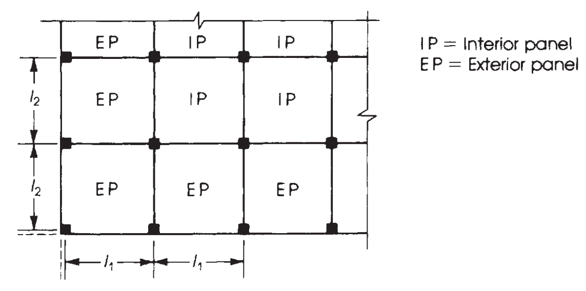
фигура 8. Определение панелей в соответствии с их относительным положением в плане плиты. (Надим Хассунд и Актем Ай-Маназер, “Теория и дизайн конструкционного бетона”)
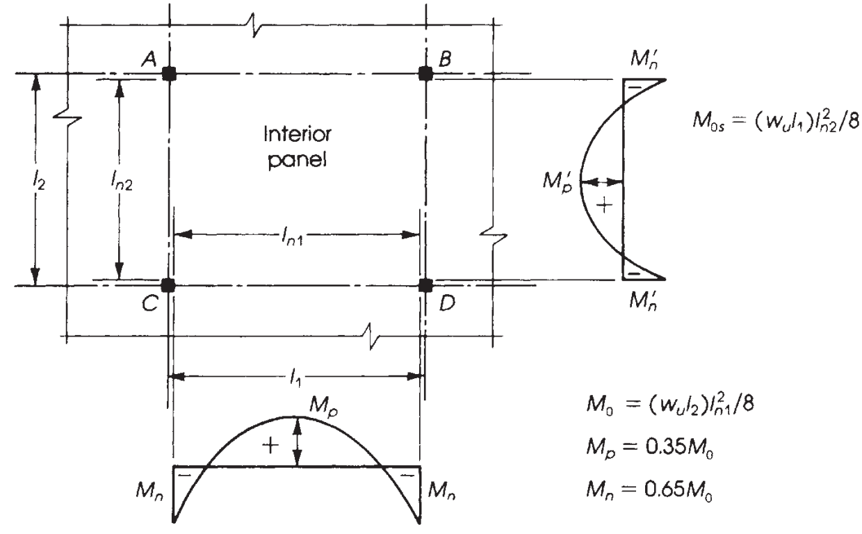
фигура 9. Распределение моментов во внутренней панели. (Надим Хассунд и Актем Ай-Маназер, “Теория и дизайн конструкционного бетона”)
Крайне важно знать правильное распределение моментов в зависимости от плиты, которую мы проектируем. В этом примере, У нас есть последний случай на следующем изображении (фигура 9), “Нет лучей,” нанесен на плоскую плиту или твердую плиту без луча, ни на грани, ни между опорами.
Основное различие в пяти случаях, показанных на рисунке 9 Является ли фракции, которые будут назначены на внешних панелях, в котором относительная сдержанность в конце изменяет значения, которые должны быть рассчитаны.
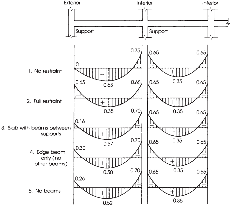
фигура 10. Распределение общего статического момента в отрицательные и положительные моменты. (Надим Хассунд и Актем Ай-Маназер, “Теория и дизайн конструкционного бетона”)
Распределение общего факторированного момента \({M_0}\) за пролет в отрицательные и положительные моменты.
Один раз \({M_0}\) был рассчитан, Настало время назначить долю моментов в положительные и отрицательные в каждой дизайнерской полосе, то есть, колонна и средние полосы. Для большей ясности, фигура 10 Помогает указать соответствующий фактор, который следует учитывать при распределении общего момента.
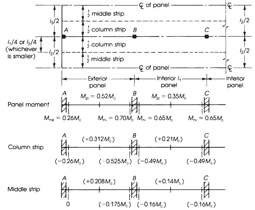
фигура 11. Ширина эквивалентной жесткой рамы и распределения моментов в плоских плитах. (Надим Хассунд и Актем Ай-Маназер, “Теория и дизайн конструкционного бетона”)
Используя предыдущие факторы, указанные на рисунке 10, Мы получаем в следующей таблице окончательный момент.
Продольное направление: \({M_0 = 189.97 кН-м}\)
| Охватывать (Эс:Экстерьер, ЯВЛЯЕТСЯ:Интерьер) | Общий момент (кН-м) | Столевая полоса (кН-м) | Средняя полоса (кН-м) |
|---|---|---|---|
| Внешний отрицательный ES | 0.26M0 = 49,39 | 0.26M0 = 49,39 | 0 |
| Положительный эс | 0.52M0 = 98,78 | 0.31M0 = 58,89 | 0.21M0 = 39,89 |
| Внутренняя негативная эс | 0.70M0 = 132,98 | 0.53M0 = 100,68 | 0.17M0 = 32,29 |
| Положительный есть | 0.35M0 = 66,49 | 0.21M0 = 39,89 | 0.14M0 = 26,60 |
| Негатив | 0.65M0 = 123,48 | 0.49M0 = 93,09 | 0.16M0 = 30,40 |
С моментом, который раздался, Настало время определить армирование стальной арматуры, которое будет помещено в плиту. Мы разработаем только один расчет, а затем все результаты в таблице.
Момент в внешнем отрицательном промежутке в полосе колонны, \({M_u = 49.39 кН-м}\)
- Предполагаемая секция с контролируемым натяжением. \({\фи_ф = 0.9}\)
- Ширина полосы колонны, \({b = 2,0 м}\)
- Область стального армирования, \({A_s = frac{М_у}{\phi_ftimes 0,9dtimes fy}= frac{49.39кН-м}{0.9\раз 0.9(0.17м)\раз 420 МПа}= 853,996 {мм}^ 2}\)
- \({\расстояние от центра колонны{мин} знак равно 0.0018}\). Минимальная площадь армирования стали, \({A_{s,мин}=ро_{мин}\раз btimes d = 0.0018 \times 2.0m \times 0.17m =612 {мм}^ 2}\). Сейчас же, проверьте, ведет себя ли секция как управляемая по натяжению.
- \({а = фрак{A_stimes f_y}{0.85\раз f’ctimes b} = frac{853.996 {мм}^2раз 420 МПа}{0.85\раз 25 MPa\times 2.0m }знак равно 8.439 мм}\)
- \({с = гидроразрыв{а }{\бета_1}= Гидроразрыва{8.439 мм}{0.85} = 9,929 мм }\)
- \({\варепсилон_t = (\гидроразрыва{0.003}{с})\раз d – 0.003 знак равно (\гидроразрыва{0.003}{9.929мм})\раз 170 мм – 0.003 знак равно 0.048 > 0.005 }\) Ok!, это раздел с контролируемым напряжением!.
| Охватывать(Эс:Экстерьер, ЯВЛЯЕТСЯ:Интерьер) | Столевая полоса (кН-м) | \({A_{s,расчет} ({мм}^ 2)}\) | \({A_{s,мин} ({мм}^ 2)}\) | \({а (мм)}\) | \({с (мм)}\) | \({\varepsilon_t > 0.005}\) |
|---|---|---|---|---|---|---|
| Внешний отрицательный ES | 49.39 | 853.996 | 612.0 | 8.439 | 9.929 | 0.048 > 0.005! |
| Положительный эс | 58.89 | 1018.259 | 612.0 | 10.063 | 11.839 | 0.040 > 0.005! |
| Внутренняя негативная эс | 100.68 | 1740.844 | 612.0 | 17.204 | 20.24 | 0.022 > 0.005! |
| Положительный есть | 39.89 | 689.733 | 612.0 | 6.816 | 8.019 | 0.06 > 0.005! |
| Негатив | 93.09 | 1609.607 | 612.0 | 15.907 | 18.714 | 0.024 > 0.005! |
Момент в внешнем положительном промежутке в средней полосе, \({M_u = 39.89 кН-м}\)
- Предполагаемая секция с контролируемым натяжением. \({\фи_ф = 0.9}\)
- Ширина средней полосы, \({b = 2,0 м}\)
- Область стального армирования, \({A_s = frac{М_у}{\phi_ftimes 0,9dtimes fy}= frac{39.89кН-м}{0.9\раз 0.9(0.17м)\раз 420 МПа}= 689,733 {мм}^ 2}\)
- \({\расстояние от центра колонны{мин} знак равно 0.0018}\). Минимальная площадь армирования стали, \({A_{s,мин}=ро_{мин}\раз btimes d = 0.0018 \times 2.0m \times 0.17m =612 {мм}^ 2}\). Сейчас же, проверьте, ведет себя ли секция как управляемая по натяжению.
- \({а = фрак{A_stimes f_y}{0.85\раз f’ctimes b} = frac{689.766 {мм}^2раз 420 МПа}{0.85\раз 25 MPa\times 2.0m }знак равно 6.816 мм}\)
- \({с = гидроразрыв{а }{\бета_1}= Гидроразрыва{6.816 мм}{0.85} знак равно 8.019 мм }\)
- \({\варепсилон_t = (\гидроразрыва{0.003}{с})\раз d – 0.003 знак равно (\гидроразрыва{0.003}{8.019мм})\раз 170 мм – 0.003 знак равно 0.0605 > 0.005 }\) Ok!, это раздел с контролируемым напряжением!.
| Охватывать(Эс:Экстерьер, ЯВЛЯЕТСЯ:Интерьер) | Средняя полоса (кН-м) | \({A_{s,расчет} ({мм}^ 2)}\) | \({A_{s,мин} ({мм}^ 2)}\) | \({а (мм)}\) | \({с (мм)}\) | \({\varepsilon_t > 0.005}\) |
|---|---|---|---|---|---|---|
| Внешний отрицательный ES | 0 | 0.00 | 612.0 | 6.048 | 7.115 | 0.069 > 0.005! |
| Положительный эс | 39.89 | 689.733 | 612.0 | 6.816 | 8.019 | 0.061 > 0.005! |
| Внутренняя негативная эс | 32.29 | 558.322 | 612.0 | 6.048 | 7.115 | 0.069 > 0.005! |
| Положительный есть | 26.60 | 459.937 | 612.0 | 6.048 | 7.115 | 0.069 > 0.005! |
| Негатив | 30.40 | 525.642 | 612.0 | 6.048 | 7.115 | 0.069 > 0.005! |
Поперечное направление: \({M_0 = 115.40 кН-м}\)
| Охватывать (Эс:Экстерьер, ЯВЛЯЕТСЯ:Интерьер) | Общий момент (кН-м) | Столевая полоса (кН-м) | Средняя полоса (кН-м) |
|---|---|---|---|
| Внешний отрицательный ES | 0.26M0 = 30,00 | 0.26M0 = 30,00 | 0 |
| Положительный эс | 0.52M0 = 60,00 | 0.31M0 = 35,77 | 0.21M0 = 24,23 |
| Внутренняя негативная эс | 0.70M0 = 80,78 | 0.53M0 = 61,16 | 0.17M0 = 19,62 |
| Положительный есть | 0.35M0 = 40,39 | 0.21M0 = 24,23 | 0.14M0 = 16,16 |
| Негатив | 0.65M0 = 75,01 | 0.49M0 = 56,55 | 0.16M0 = 18,46 |
С моментом, который раздался, Пришло время определить усиление стальной арматуры, чтобы поместить в плиту. Мы разработаем только один расчет, а затем все результаты в таблице.
Момент в внешнем отрицательном промежутке в полосе колонны, \({M_u = 30.00 кН-м}\)
- Предполагаемая секция с контролируемым натяжением. \({\фи_ф = 0.9}\)
- Ширина полосы колонны, \({b = 2,0 м}\)
- Область стального армирования, \({A_s = frac{М_у}{\phi_ftimes 0,9dtimes fy}= frac{30.00кН-м}{0.9\раз 0.9(0.17м)\раз 420 МПа}= 518,726 {мм}^ 2}\)
- \({\расстояние от центра колонны{мин} знак равно 0.0018}\). Минимальная площадь армирования стали, \({A_{s,мин}=ро_{мин}\раз btimes d = 0.0018 \times 2.0m \times 0.17m =612 {мм}^ 2}\). Сейчас же, проверьте, ведет себя ли секция как управляемая по натяжению.
- \({а = фрак{A_stimes f_y}{0.85\раз f’ctimes b} = frac{518.726 {мм}^2раз 420 МПа}{0.85\раз 25 MPa\times 2.0m }знак равно 6.048 мм}\)
- \({с = гидроразрыв{а }{\бета_1}= Гидроразрыва{6.048 мм}{0.85} = 7,115 мм }\)
- \({\варепсилон_t = (\гидроразрыва{0.003}{с})\раз d – 0.003 знак равно (\гидроразрыва{0.003}{7.115мм})\раз 170 мм – 0.003 знак равно 0.069 > 0.005 }\) Ok!, это раздел с контролируемым напряжением!.
| Охватывать(Эс:Экстерьер, ЯВЛЯЕТСЯ:Интерьер) | Столевая полоса (кН-м) | \({A_{s,расчет} ({мм}^ 2)}\) | \({A_{s,мин} ({мм}^ 2)}\) | \({а (мм)}\) | \({с (мм)}\) | \({\varepsilon_t > 0.005}\) |
|---|---|---|---|---|---|---|
| Внешний отрицательный ES | 30.00 | 518.726 | 612.0 | 6.048 | 7.115 | 0.069 > 0.005! |
| Положительный эс | 35.77 | 618.494 | 612.0 | 6.112 | 7.191 | 0.068 > 0.005! |
| Внутренняя негативная эс | 61.16 | 1057.509 | 612.0 | 10.451 | 12.295 | 0.038 > 0.005! |
| Положительный есть | 24.23 | 418.958 | 612.0 | 6.048 | 7.115 | 0.069 > 0.005! |
| Негатив | 56.55 | 977.799 | 612.0 | 9.663 | 11.368 | 0.042 > 0.005! |
Момент в внешнем положительном промежутке в средней полосе, \({M_u = 24.23 кН-м}\)
- Предполагаемая секция с контролируемым натяжением. \({\фи_ф = 0.9}\)
- Ширина полосы колонны, \({b = 4,0 м}\)
- Область стального армирования, \({A_s = frac{М_у}{\phi_ftimes 0,9dtimes fy}= frac{24.23 кН-м}{0.9\раз 0.9(0.17м)\раз 420 МПа}= 418,958 {мм}^ 2}\)
- \({\расстояние от центра колонны{мин} знак равно 0.0018}\). Минимальная площадь армирования стали, \({A_{s,мин}=ро_{мин}\раз btimes d = 0.0018 \times 4.0m \times 0.17m =1224 {мм}^ 2}\). Сейчас же, проверьте, ведет себя ли секция как управляемая по натяжению.
- \({а = фрак{A_stimes f_y}{0.85\раз f’ctimes b} = frac{1224 {мм}^2раз 420 МПа}{0.85\раз 25 MPa\times 4.0m }знак равно 6.048 мм}\)
- \({с = гидроразрыв{а }{\бета_1}= Гидроразрыва{6.048 мм}{0.85} знак равно 7.115 мм }\)
- \({\варепсилон_t = (\гидроразрыва{0.003}{с})\раз d – 0.003 знак равно (\гидроразрыва{0.003}{7.115мм})\раз 170 мм – 0.003 знак равно 0.069 > 0.005 }\) Ok!, это раздел с контролируемым напряжением!.
| Охватывать(Эс:Экстерьер, ЯВЛЯЕТСЯ:Интерьер) | Средняя полоса (кН-м) | \({A_{s,расчет} ({мм}^ 2)}\) | \({A_{s,мин} ({мм}^ 2)}\) | \({а (мм)}\) | \({с (мм)}\) | \({\varepsilon_t > 0.005}\) |
|---|---|---|---|---|---|---|
| Внешний отрицательный ES | 0.00 | 0.00 | 1224.00 | 6.048 | 7.115 | 0.069 > 0.005! |
| Положительный эс | 24.23 | 418.958 | 1224.00 | 6.048 | 7.115 | 0.069 > 0.005! |
| Внутренняя негативная эс | 19.62 | 339.247 | 1224.00 | 6.048 | 7.115 | 0.069 > 0.005! |
| Положительный есть | 16.16 | 279.420 | 1224.00 | 6.048 | 7.115 | 0.069 > 0.005! |
| Негатив | 18.46 | 319.189 | 1224.00 | 6.048 | 7.115 | 0.069 > 0.005! |
Если вы новичок в SkyCiv, Зарегистрируйтесь и протестируйте программу самостоятельно!
Модуль дизайна Skyciv S3D
В этой секции, Мы описываем результат дизайна, используя модуль для дизайна пластин, включенный в Skyciv. Мы не объясняем, как моделировать и анализировать структуру (для этих, см. соответствующие статьи по этой теме в нашей документации.: Как смоделировать конструкцию в SkyCiv?, Как применять нагрузки в моей модели здания? и Как запустить линейный упругий анализ?)
На плиты удобно наносить мелкую сетку для получения точного результата проектирования.. Пожалуйста, взгляните на следующее изображение для большей ясности..
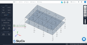
фигура 12. Более мелкая сетка применяется к плитам
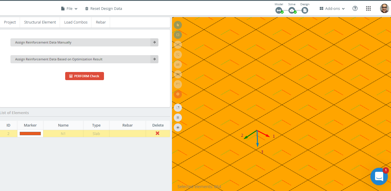
Следующим шагом будет запуск модуля проектирования и выбор опций, позволяющих рассчитать оптимизированную площадь стальной арматуры..
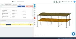
фигура 13. Определение свойств бетонной плиты перед оптимизацией проекта.
фигура 14 представляет ориентацию локальных осей пластины. Поскольку местная ось 3 вниз, в “верхняя” это дно, и “низ” будет топ, таким образом правильно взяв данные из проекта.
Еще одним важным фактом является размер ячейки плиты.; это пластинчатый квадратный элемент с размерами в плане 500х500мм.. Skyciv S3D дает область подкрепления в качестве интегрированного значения на конечный элемент. таким образом, Если мы хотим получить общую зону арматуры колонны или средней полосы, Нам нужно рассчитать среднее значение по количеству элементов, которые суммируют ширину полосы, анализируемую. Например, Для полосы колонки, Четыре элемента будут рассмотрены (4×0.5М = 2м).
фигура 14. Ориентация локальной оси в примере плиты.
Первый, Мы анализируем область подкрепления, необходимую вдоль продольного направления по оси 1.
Полоса колонны
- Внешний негативный момент (Верхнее подкрепление): \({A_{s,верхняя} знак равно(119.09\раз 2 + 952.72 + 833.64 )\гидроразрыва{{мм}^ 2}{м} \раз 0,50 м = 1012.27 {мм}^ 2}\)
- Внешний положительный момент (нижнее подкрепление): \({A_{s,бот} знак равно 4*463.90 \гидроразрыва{{мм}^ 2}{м}\раз 0,50 м = 927.80 {мм}^ 2}\)
- Внешний внутренний негативный момент (Верхнее подкрепление): \({A_{s,верхняя} знак равно(1071.82\раз 2 +714.54 \раз 2 )\гидроразрыва{{мм}^ 2}{м} \раз 0,50 м = 1786.36 {мм}^ 2}\)
- Внутренний положительный момент(нижнее подкрепление): \({A_{s,бот} знак равно 4*309.27 \гидроразрыва{{мм}^ 2}{м}\раз 0,50 м = 618.54 {мм}^ 2}\)
- Внутренний негативный момент (Верхнее подкрепление): \({A_{s,верхняя} знак равно(714.54\раз 2 +952.73 \раз 2 )\гидроразрыва{{мм}^ 2}{м} \раз 0,50 м = 1667.27 {мм}^ 2}\)
Средняя полоса
- Внешний негативный момент (Верхнее подкрепление): \({A_{s,верхняя} знак равно(119.09\раз 4)\гидроразрыва{{мм}^ 2}{м} \раз 0,50 м = 238.18 {мм}^ 2}\)
- Внешний положительный момент (нижнее подкрепление): \({A_{s,бот} знак равно (463.90\раз 2 +412.36 \раз 2 ) \гидроразрыва{{мм}^ 2}{м}\раз 0,50 м = 876.26 {мм}^ 2}\)
- Внешний внутренний негативный момент (Верхнее подкрепление): \({A_{s,верхняя} знак равно(357.27\раз 2 +476.36 \раз 2 )\гидроразрыва{{мм}^ 2}{м} \раз 0,50 м = 833.63 {мм}^ 2}\)
- Внутренний положительный момент(нижнее подкрепление): \({A_{s,бот} знак равно 4*257.72 \гидроразрыва{{мм}^ 2}{м}\раз 0,50 м = 515.44 {мм}^ 2}\)
- Внутренний негативный момент (Верхнее подкрепление): \({A_{s,верхняя} знак равно(357.27\раз 2 +476.36 \раз 2 )\гидроразрыва{{мм}^ 2}{м} \раз 0,50 м = 833.63 {мм}^ 2}\)
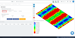
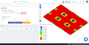
фигура 15. Оптимизация приводит к направлению “1” И верхняя сторона (Нижняя сторона, на самом деле).
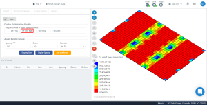
фигура 16. Оптимизация приводит к направлению “1” И нижняя сторона (Верхняя сторона, на самом деле).
В завершение, Мы анализируем область усиления, необходимая вдоль поперечного направления по оси 2.
Полоса колонны
- Внешний негативный момент (Верхнее подкрепление): \({A_{s,верхняя} знак равно(91.55\раз 2 + 457.73 + 549.28 )\гидроразрыва{{мм}^ 2}{м} \раз 0,50 м = 595.055 {мм}^ 2}\)
- Внешний положительный момент (нижнее подкрепление): \({A_{s,бот} знак равно (269.68\раз 3+239.72) \гидроразрыва{{мм}^ 2}{м}\раз 0,50 м = 524.38 {мм}^ 2}\)
- Внешний внутренний негативный момент (Верхнее подкрепление): \({A_{s,верхняя} знак равно(823.92\раз 2 +549.28 +457.73)\гидроразрыва{{мм}^ 2}{м} \раз 0,50 м = 1327.43 {мм}^ 2}\)
- Внутренний положительный момент(нижнее подкрепление): \({A_{s,бот} знак равно (179.79\раз 3+149.82) \гидроразрыва{{мм}^ 2}{м}\раз 0,50 м = 344.60 {мм}^ 2}\)
- Внутренний негативный момент (Верхнее подкрепление): \({A_{s,верхняя} знак равно(823.92\раз 2 +549.28 +457.73)\гидроразрыва{{мм}^ 2}{м} \раз 0,50 м = 1327.43 {мм}^ 2}\)
Средняя полоса
- Внешний негативный момент (Верхнее подкрепление): \({A_{s,верхняя} знак равно(183.09\times 2+91.55\times 6)\гидроразрыва{{мм}^ 2}{м} \раз 0,50 м = 457.74 {мм}^ 2}\)
- Внешний положительный момент (нижнее подкрепление): \({A_{s,бот} знак равно (209.75\раз 2 +179.79 \раз 2 +149.82 \раз 4) \гидроразрыва{{мм}^ 2}{м}\раз 0,50 м = 689.18{мм}^ 2}\)
- Внешний внутренний негативный момент (Верхнее подкрепление): \({A_{s,верхняя} знак равно(274.64\times 2+91.55\times 6)\гидроразрыва{{мм}^ 2}{м} \раз 0,50 м = 549.29 {мм}^ 2}\)
- Внутренний положительный момент(нижнее подкрепление): \({A_{s,бот} знак равно (119.86\раз 4 + 89.89\раз 4) \гидроразрыва{{мм}^ 2}{м}\раз 0,50 м = 419.50 {мм}^ 2}\)
- Внутренний негативный момент (Верхнее подкрепление): \({A_{s,верхняя} знак равно(274.64\times 2+91.55\times 6 )\гидроразрыва{{мм}^ 2}{м} \раз 0,50 м = 549.29 {мм}^ 2}\)
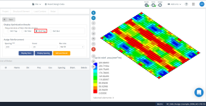
фигура 17. Оптимизация приводит к направлению “2” И верхняя сторона (Нижняя сторона, на самом деле).
фигура 18. Оптимизация приводит к направлению “2” И нижняя сторона (Верхняя сторона, на самом деле).
Сравнение результатов
В следующей таблице показаны результаты для DDM (“Метод прямой проектирования”) и оптимизация стальной арматуры S3D.
| Охватывать (Эс:Экстерьер, ЯВЛЯЕТСЯ:Интерьер) | Полоса колонны (S3D Design) \({Как ({мм}^ 2)}\) | Полоса колонны (ACI-318 DDM) \({Как ({мм}^ 2)}\) | % Дифференциал | Средняя полоса (S3D Design) \({Как ({мм}^ 2)}\) | Средняя полоса (ACI-318 DDM) \({Как ({мм}^ 2)}\) | % Дифференциал |
|---|---|---|---|---|---|---|
| Внешний отрицательный ES | 1012.27 | 853.996 | 15.636 | 238.18 | 0 (612.0) | 100.00 |
| Положительный эс | 927.80 | 1018.259 | 9.75 | 876.26 | 689.733 | 21.287 |
| Внутренняя негативная эс | 1786.36 | 1740.844 | 2.48 | 833.63 | 558.322 (612.0) | 26.586 |
| Положительный есть | 618.54 | 689.733 | 11.51 | 515.44 | 459.937 (612.0) | 18.734 |
| Негатив | 1667.27 | 1609.607 | 3.459 | 833.63 | 525.642 (612.0) | 26.586 |
Поперечное направление
| Охватывать (Эс:Экстерьер, ЯВЛЯЕТСЯ:Интерьер) | Полоса колонны (S3D Design) \({Как ({мм}^ 2)}\) | Полоса колонны (ACI-318 DDM) \({Как ({мм}^ 2)}\) | % Дифференциал | Средняя полоса (S3D Design) \({Как ({мм}^ 2)}\) | Средняя полоса (ACI-318 DDM) \({Как ({мм}^ 2)}\) | % Дифференциал |
|---|---|---|---|---|---|---|
| Внешний отрицательный ES | 595.055 | 518.726 | 12.827 | 457.74 | 0 (1224) | 100.00 |
| Положительный эс | 524.38 | 618.494 | 17.948 | 689.18 | 418.958 | 39.209 |
| Внутренняя негативная эс | 1327.43 | 1057.509 | 20.334 | 549.29 | 339.247 | 38.239 |
| Положительный есть | 344.60 | 418.958 | 21.578 | 419.50 | 279.42 | 33.392 |
| Негатив | 1327.43 | 977.799 | 26.339 | 549.29 | 319.189 | 41.891 |
Вывод
В этой статье мы продемонстрировали, что модуль Skyciv для конструкции пластины рассчитывает стальное усиление для изгибающих плитов соответственно с кодом ACI-318-19. Сравнение результатов анализа в полосках столбцов, где из -за их относительной жесткости, Моменты высоко сконцентрированы, Различия между расчетами рук и оптимизацией по S3D округу значения 10 – 15%. Эта практичность указывает на отличное соответствие между анализом и процедурами проектирования.
Для средних полос, Результаты различаются немного больше, потому что код назначает только остаток момента после получения соответствующих полос столбцов. Это повлияет на матч, когда мы сравним его с анализом из программного обеспечения, что более точное.
Впервые в SkyCiv? Зарегистрируйтесь и попробуйте программное обеспечение самостоятельно!