
Моментное соединение фланцевой пластины передает изгиб балки к стыку колонны, превращая момент балки в пару сил.: напряжение в одной фланцевой пластине, сжатие в другом. Отдельная перемычка несет нагрузку на сдвиг.. Именно это разделение делает соединение простым в проектировании и создании., потому что у каждого компонента есть одна работа.
Обычная конструкция представляет собой пластину, прикрепленную болтами к полке балки и приваренную к колонне.. Где рама собирается в заводских условиях, вместо этого все соединение можно сварить. Стенка обычно крепится болтами к стенке балки и приваривается к колонне..
SkyCiv Connection Design проверяет всю сборку на соответствие Aisc 360-16 в ASD или LRFD. Вы вводите сечения балок и колонн, размеры пластины, болты и сварные швы, и нагрузки; он возвращает каждый чек с его коэффициентом использования и стоящим за ним пунктом.
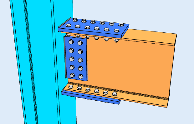
Вид с высоты
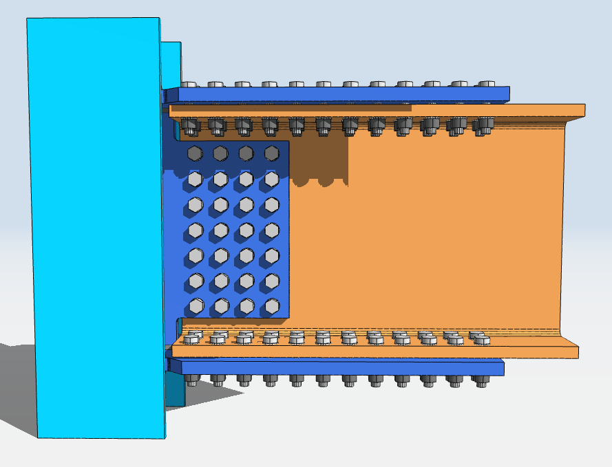
Вид сверху
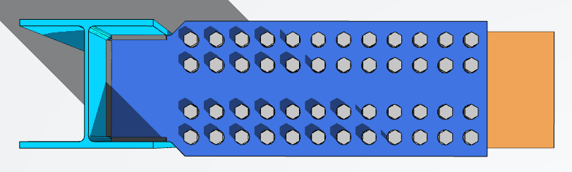
Проектирование соединения фланцевой пластины в SkyCiv
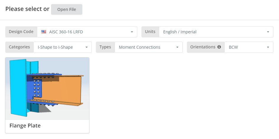
Код дизайна может быть AISC. 360-16 ASD или LRFD, и единицы измерения английский/имперский или СИ/метрический. Ориентация: BCF или BCW.; наведите курсор на всплывающую подсказку, чтобы узнать, что каждый означает. Щелкните значок “Фланцевая пластина” плитка.
Детали вкладка
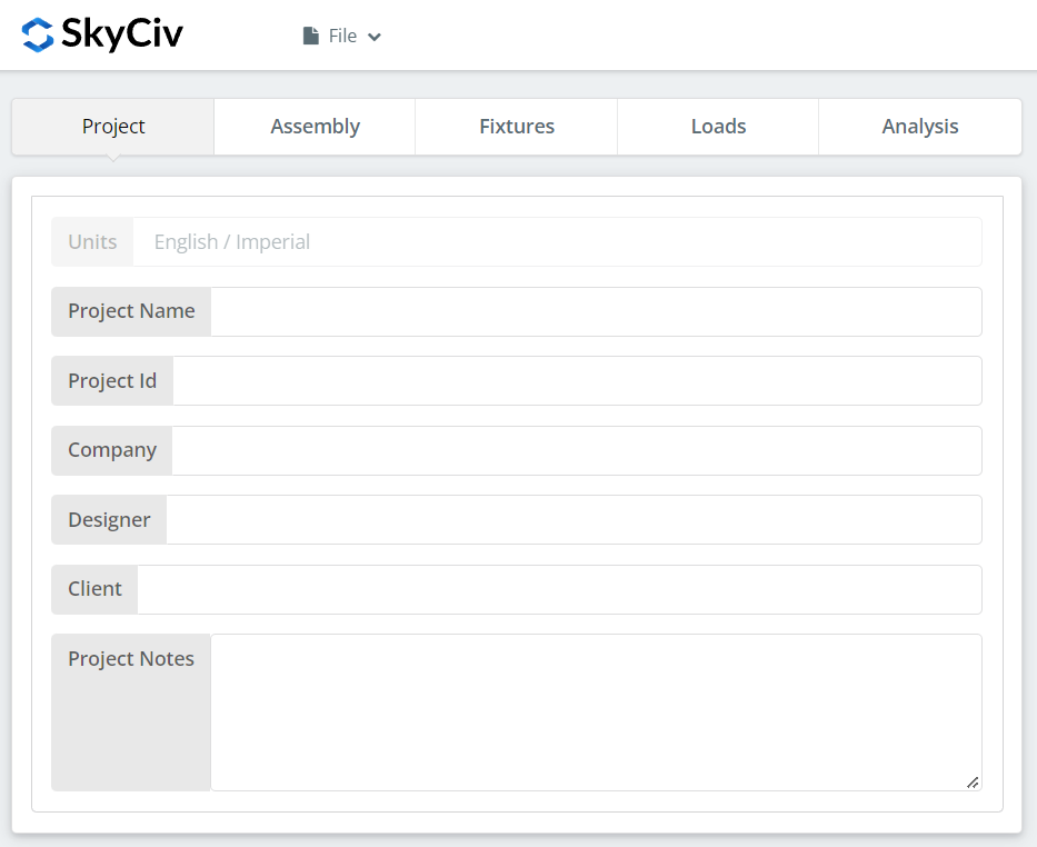
Запишите подробности проекта здесь. Ничто из этого не меняет расчеты, но это входит в отчет.
Вкладка "Сборка"
Три вкладки находятся под сборкой.: Колонка, Луч, и связь, который удерживает как полку, так и стенку.
Вкладка столбца
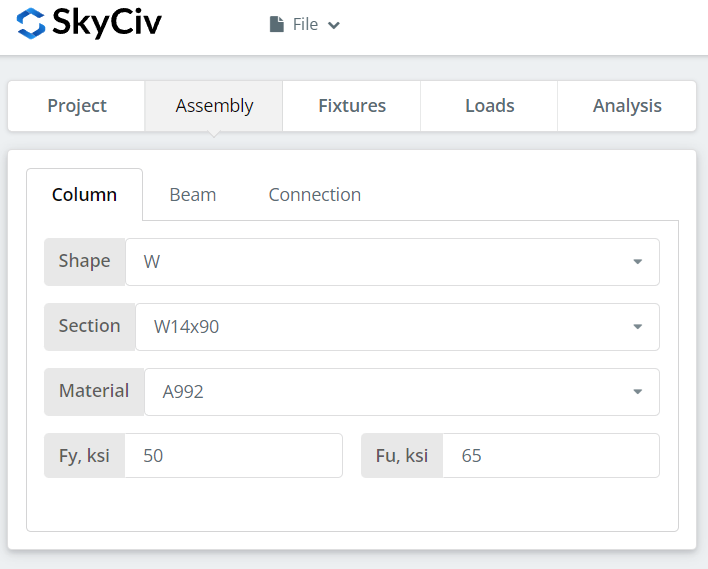
Укажите сечение и марку материала колонны. А992 и А36 есть в списке; для всего остального выберите «Пользовательский» и введите Fy и Fu..
Вкладка «Луч»
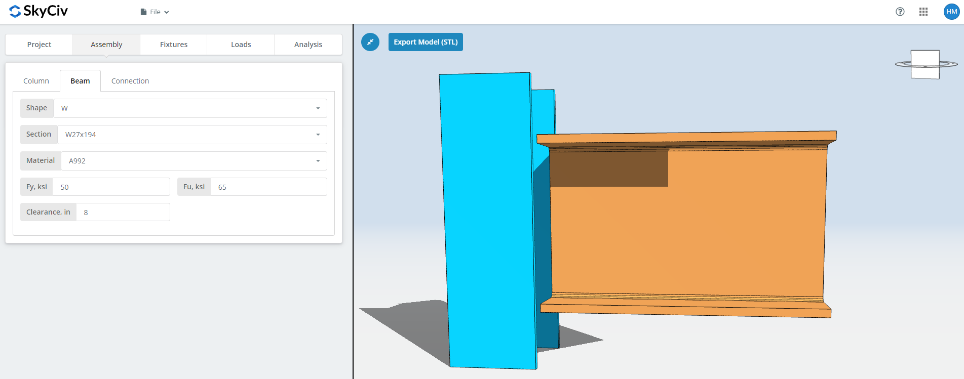
Те же входы для луча, плюс зазор между балками.
Вкладка «Подключение»: Фланцевая пластина
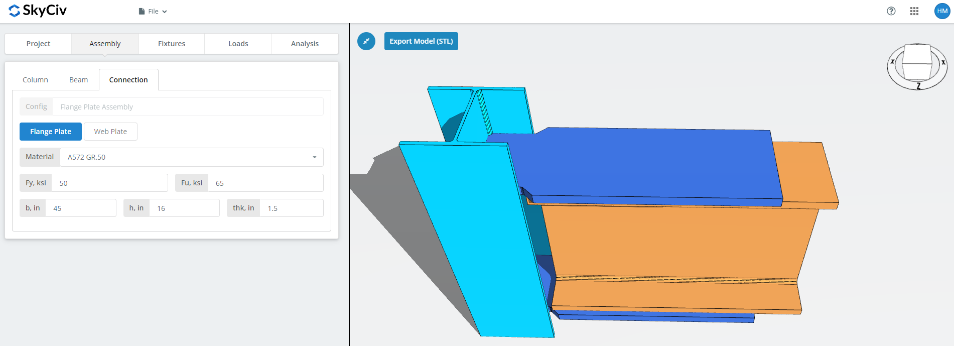
Задайте свойства фланцевой пластины: класс А36, А992 или А572 гр.50, или на заказ со своими Fy и Fu, тогда б (ширина), час (рост) и спасибо (толщина).
Это тарелка, которая несет в себе момент, так что его площадь и затворная группа в нем - это то, до чего сводится допустимый момент. Наблюдайте за 3D-рендерингом по мере ввода и проверяйте, есть ли место для болтов или сварных швов, которые вы определите на вкладке «Средства»..
Вкладка «Подключение»: Вы можете заметить, что основное отличие заключается в соединении полок балки с опорной колонной.
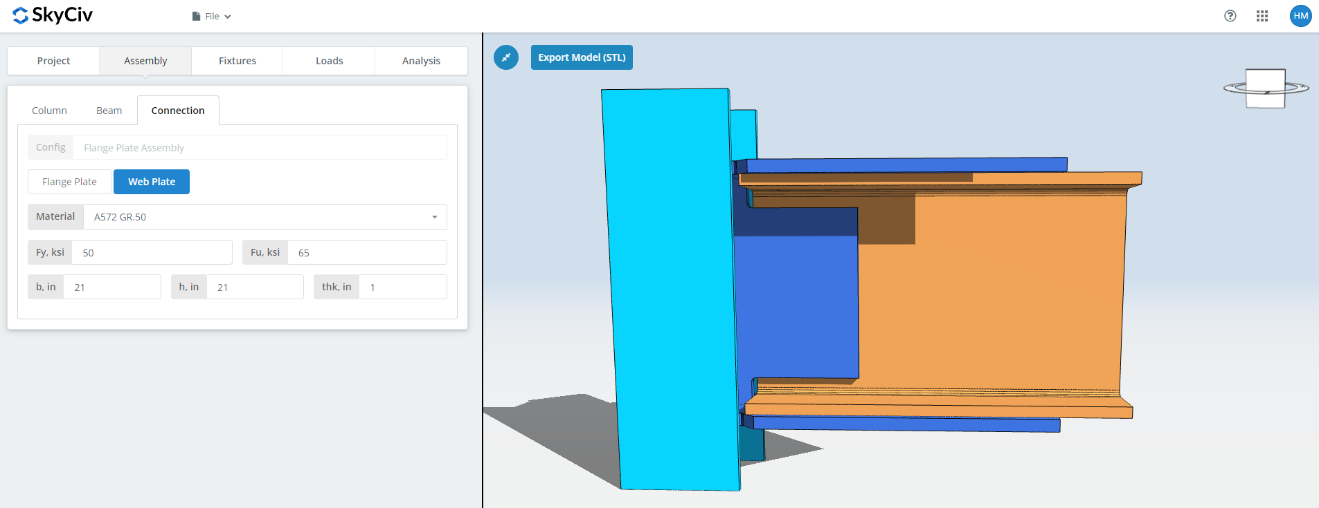
Те же поля для веб-таблицы. Этот несет сдвиг, поэтому его глубина и группа болтов рассчитаны с учетом вертикальной нагрузки, а не момента. Проверьте рендер еще раз, прежде чем двигаться дальше..
приспособление 1 Вкладка
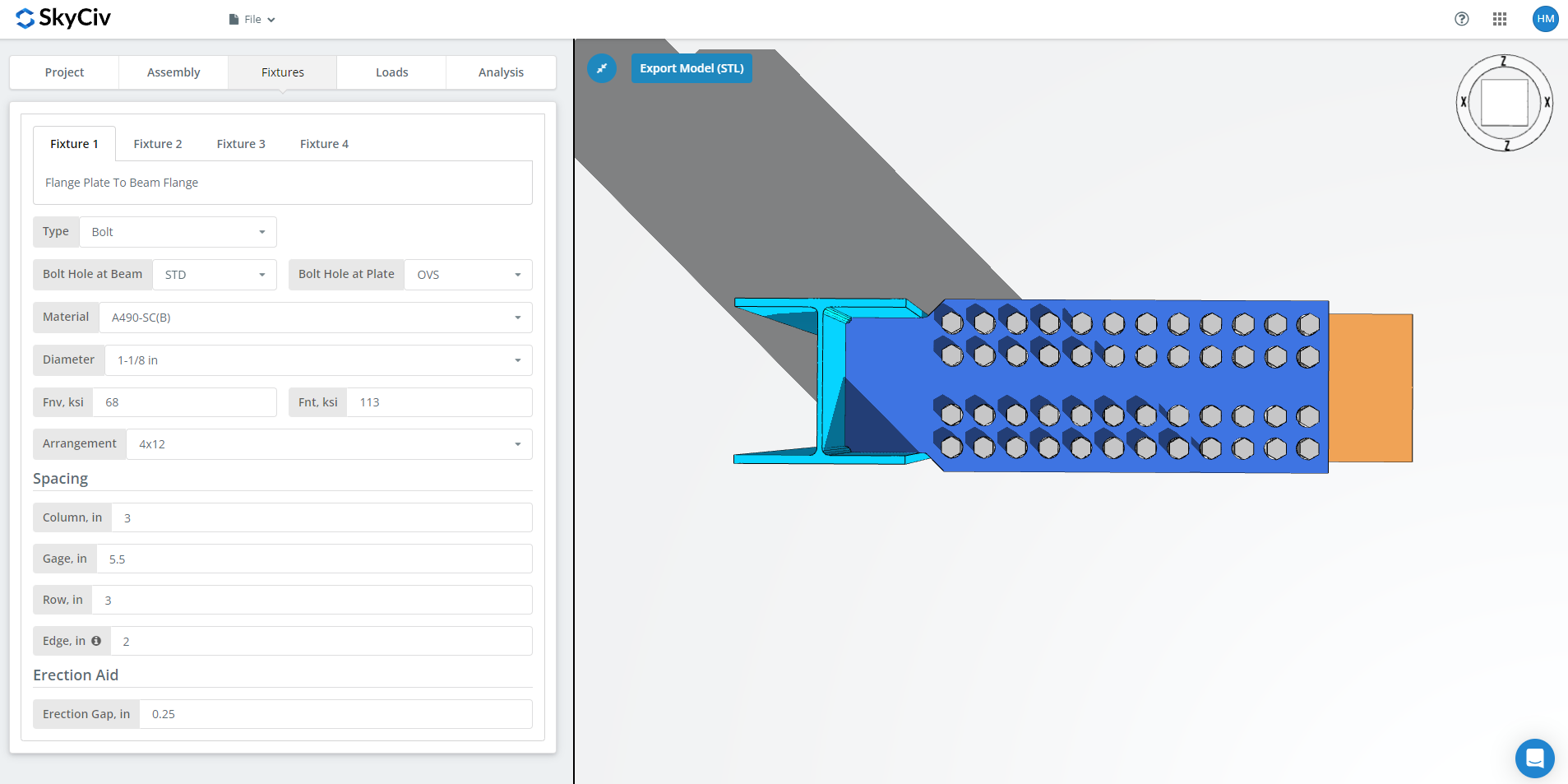
приспособление 1 это соединение фланцевой пластины с фланцем балки. Он может быть скреплен болтами или сварен.; в этом пошаговом руководстве используются болтовые соединения.
Первый, типы отверстий под болты на полке балки и на полочной пластине. Производители обычно просят стандартные отверстия. (ЗППП) в члене и негабаритных отверстиях (ОВС) во фланцевой пластине, который покупает посадочный допуск в полевых условиях.
следующий, материал или марка болта: А307, А325, A490 или на заказ. A325 и A490 — марки согласно ASTM F3125., который объединил старые автономные спецификации. Выберите N или X для соединения подшипникового типа и SC для критического скольжения..
Соединения, критические к скольжению, имеют меньшую расчетную грузоподъемность болтов, чем подшипниковые., так что используйте их там, где скольжение действительно имеет значение: отверстия увеличенного размера или с прорезями, реверс нагрузки, или усталость. В этом примере, использование отверстий OVS в балке или пластине означает, что болты автоматически проверяются на предмет скольжения.. Между N и X, X дает большую способность болта к сдвигу., но резьбы должны быть исключены из плоскости среза, и строитель должен это знать. Между СК(А) и СК(В), СК(В) дает большую емкость и требует более тщательно подготовленной поверхности, например, коммерческая струйная очистка SSPC-SP6.
Тогда диаметр болта, с 5/8″ до 1-1/2″ или метрические эквиваленты, и расположение, вплоть до 8 болтовые ряды и 12 болтовые колонны, с междурядьем, шаг и ширина колонн. В “край” входные данные — расстояние от конца балки до первой колонны болтов..
Последний, эрекция. Это зазор, который позволяет установить балку на место на месте.. Это стоит мощности, поэтому указывайте это только там, где это действительно необходимо для эрекции, и скажи это на рисунке, когда сделаешь.
приспособление 2 Вкладка
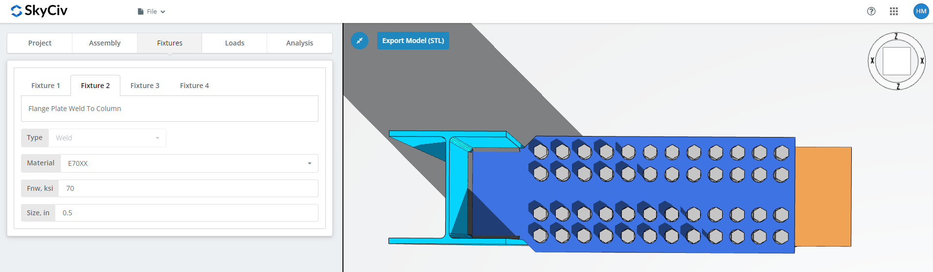
приспособление 2 это соединение фланцевой пластины с колонной, к стенке и полке колонны для BCW или к полке колонны для BCF. Этот только сварной.
Укажите сварочный материал, или выберите «Пользовательский»’ и введите Fnw, если нужного электрода нет в списке., тогда размер сварного шва.
приспособление 3 Вкладка
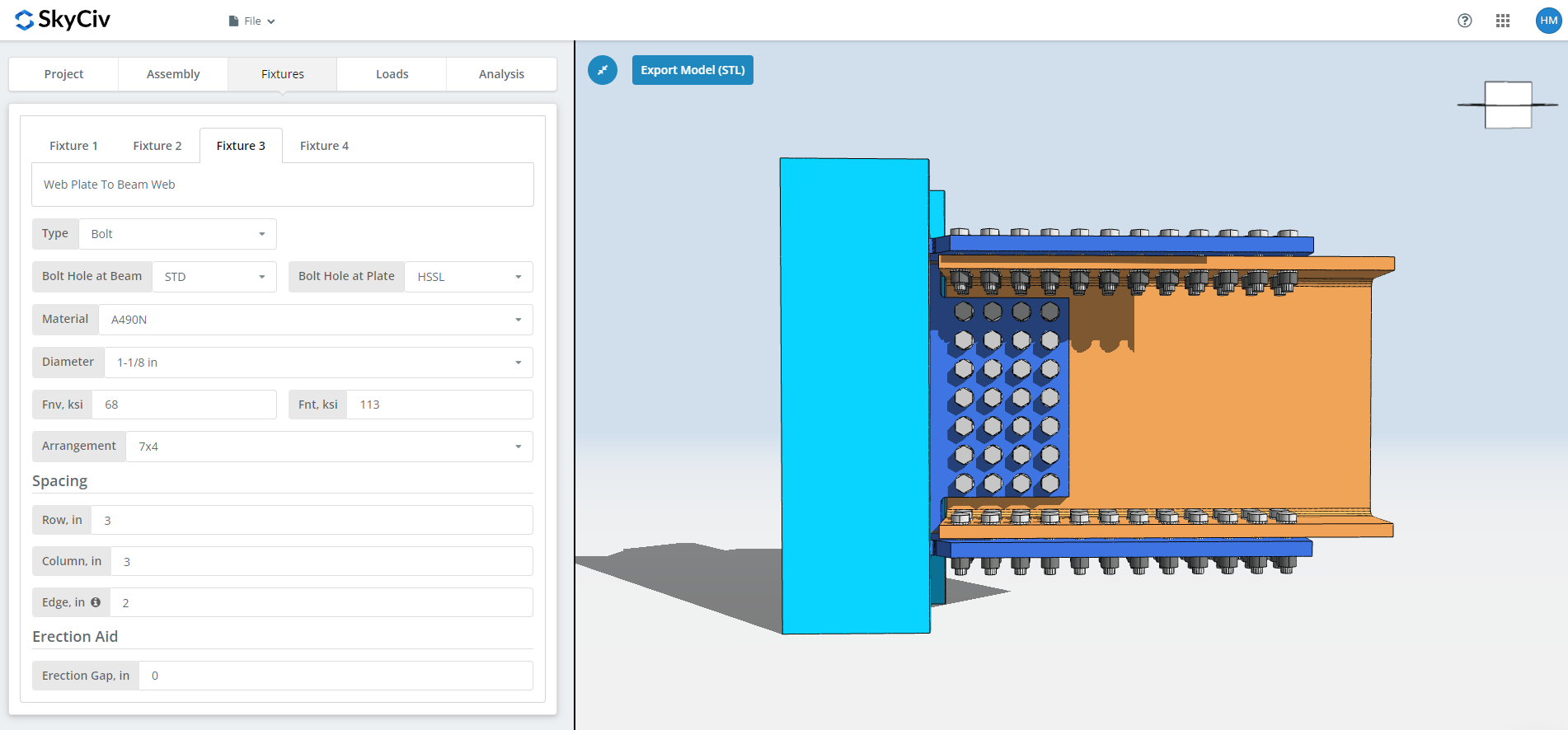
приспособление 3 это веб-плита для соединения с сетью. Он может быть скреплен болтами или сварен.; в этом пошаговом руководстве используются болтовые соединения.
Первый, типы отверстий под болты в стенке балки и в стенке балки. Производители обычно просят стандартные отверстия. (ЗППП) в элементе и горизонтальных отверстиях с короткими прорезями (HSSL) в веб-пластине.
следующий, материал или марка болта: А307, А325, A490 или на заказ, с тем же Н, Выбор X и SC в качестве приспособления 1. Приведенные выше примечания о критическом скольжении и исключении потоков применимы и здесь..
Тогда диаметр болта, с 5/8″ до 1-1/2″ или метрические эквиваленты, и расположение, вплоть до 12 болтовые ряды и 12 болтовые колонны, с расстоянием между строками и столбцами. В “край” входные данные — расстояние от конца балки до первой колонны болтов..
Последний, эрекция, как указано выше.
приспособление 4 Вкладка
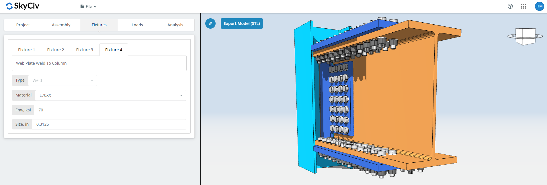
приспособление 4 является ли стенка плиты стенкой колонны или фланцевым соединением, и нравится приспособление 2 он только сварной. Укажите сварочный материал, или «Пользовательский’ со своим собственным Fnw, и размер сварного шва.
Подробнее о застежке, см. документацию по болты и сварные швы.
Вкладка "Нагрузки"
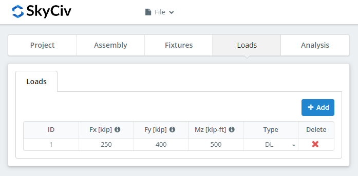
Введите горизонтальную осевую нагрузку в поле «Fx»., вертикальный сдвиг под ‘Fy’, и момент сильной оси под «Mz».
Сопоставьте нагрузки с методом расчета, который вы выбрали вначале.. LRFD принимает учтенные нагрузки в зависимости от расчетной прочности; АСД воспринимает эксплуатационные нагрузки в пределах допустимой прочности. Программное обеспечение не может определить, что вы набрали.
Результаты вкладка
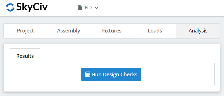
Нажмите “Выполнить проверки конструкции”. Все, что отсутствует на предыдущих вкладках, помечается здесь, а не автоматически по умолчанию..
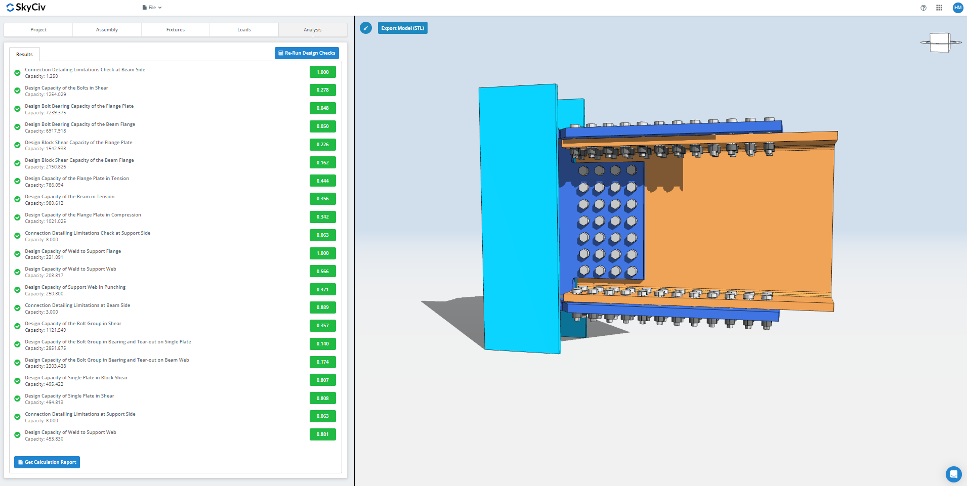
В сводке показано, прошло ли соединение, с коэффициентом использования по каждому чеку. Если это не удалось, измените входные данные на предыдущих вкладках и нажмите “Повторно запустите проверку проекта”. Когда это пройдет, “Посмотреть отчет о расчетах” открывает подробный отчет.
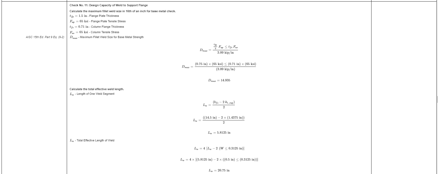
Это выдержка из отчета. Каждая проверка содержит ссылку на руководство или спецификацию AISC., и работа соответствует порядку, используемому в спецификации, поэтому инженер-рецензент может прочитать его построчно вместо того, чтобы перепроектировать число..
Вот PDF-копия полного подробного отчета о расчетах: Отчет о конструкции соединения.
Попробуйте сами
Выберите соединение фланцевой пластины, введите свои разделы, тарелки, болты и нагрузки, и просматривать каждую проверку со ссылкой на код. Он запускается в браузере, нечего устанавливать.
См. также Калькулятор соединения фланцевых пластин, в калькулятор момента соединения и момент соединения обзор.
