
The single plate connection, или срезная вкладка, is one of the simple shear connections set out in Part 10 Руководства AISC, and a fabricator favourite because it is the cheapest of the group: one plate, one weld line, one bolt group.
Пластина всегда приваривается к опоре заводским способом и обычно скрепленный болтами к соединительной балке. It can be welded to the beam instead on a shop-assembled frame. What you should not do is put that weld in the field: field welding is labour-intensive and expensive next to running a bolt in.
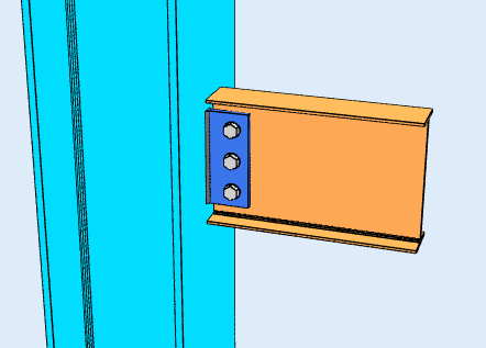
Два типа конфигурации
Which configuration you are in decides which rules apply, and it follows from the geometry rather than from a setting you choose.
-
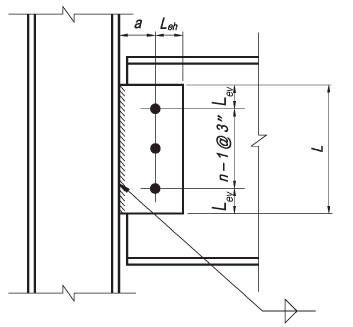
Обычная конфигурация
- Допускается только один вертикальный ряд болтов. Количество болтов в соединении должно быть между 2 и 12.
- Расстояние от линии болта до линии сварки должно быть равно или меньше 3-1/2 в.
- Стандартные отверстия (ЗППП) или горизонтальные отверстия с короткими прорезями (HSSL) разрешено использовать, как указано в таблице 10-9 руководства AISC 15-го издания.
- Расстояние до края по вертикали должно соответствовать требованиям таблицы J3.4 спецификаций AISC.. Расстояние до горизонтальной кромки должно быть больше или равно 2d как для плиты, так и для стенки балки., где d - диаметр болта.
- Либо толщина листа, либо толщина стенки балки должны соответствовать требованиям к максимальной толщине, указанным в таблице. 10-9 руководства AISC 15-го издания.

-
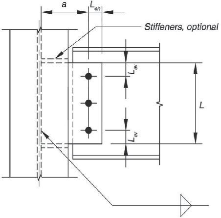
Расширенная конфигурация
- Количество болтов не ограничено.
- Расстояние от линии сварки до ближайшей к опоре линии болта не ограничивается.
- Использование отверстий должно удовлетворять требованиям раздела J3.2 Спецификации AISC..
- Расстояние до края по горизонтали и вертикали должно соответствовать требованиям таблицы J3.4 спецификаций AISC..

Designing a Single Plate Connection in SkyCiv
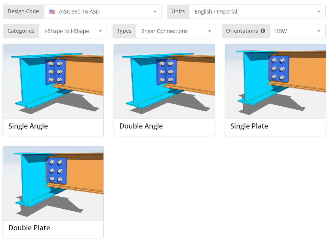
Код дизайна может быть AISC. 360-16 ASD или LRFD, и единицы измерения английский/имперский или СИ/метрический. Ориентация BCF., МЧС или толстушка; наведите курсор на всплывающую подсказку, чтобы узнать, что каждый из них означает. Щелкните значок “Одиночная плита” плитка.
Детали вкладка
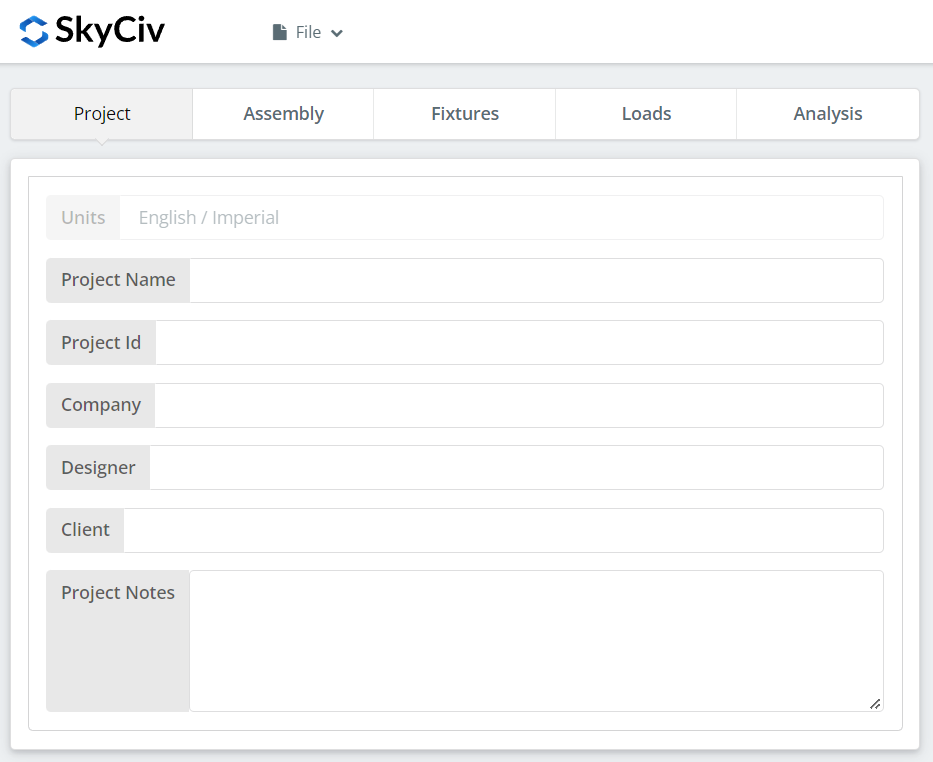
Запишите подробности проекта здесь. Ничто из этого не меняет расчеты, но это входит в отчет.
Вкладка "Сборка"
Три вкладки находятся под сборкой.: the Girder, Луч, и связь, which holds the single plate.
Вкладка «Балка»
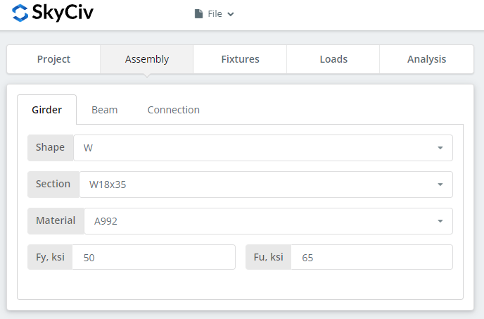
Укажите сечение и марку материала несущего элемента.. А992 и А36 есть в списке; для всего остального выберите «Пользовательский» и введите Fy и Fu..
Вкладка «Луч»
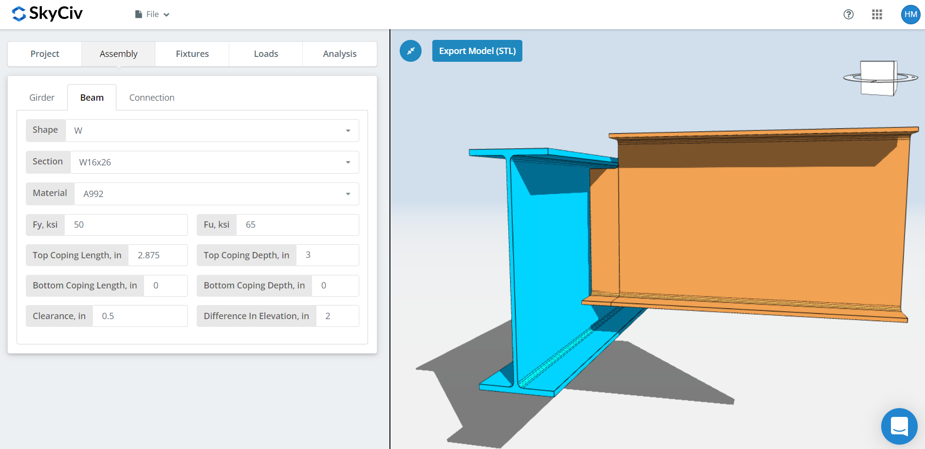
Те же входы для луча, plus cope dimensions, beam clearance and the difference in elevation.
For BBW orientation the coping is worked out automatically, and you can override it. The automatic cope recalculates whenever you change the beam section, the girder section, the clearance or the difference in elevation.
The clearance is also what puts you in one configuration or the other. A clearance small enough that the beam still sits inside the girder will usually give a conventional single plate, unless the girder flange is wide enough that the distance from the bolt to the girder web exceeds 3-1/2″. A clearance that puts the beam completely outside the girder flange gives an extended single plate. For the difference in elevation, a positive value means the beam is above the girder and a negative value below.
Вкладка «Подключение»
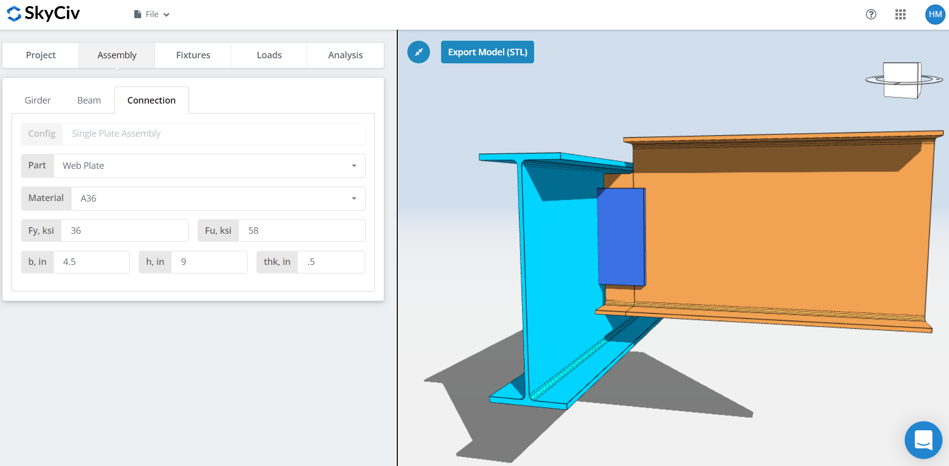
Set the plate properties: класс А36 или А992, или на заказ со своими Fy и Fu, then the plate width ‘b’, height ‘h’ and thickness ‘thk’.
Наблюдайте за 3D-рендерингом по ходу дела. The plate height should sit within the beam depth, and the plate width has to be wide enough for the beam to bolt or weld to, which matters most in an extended configuration.
приспособление 1 Вкладка
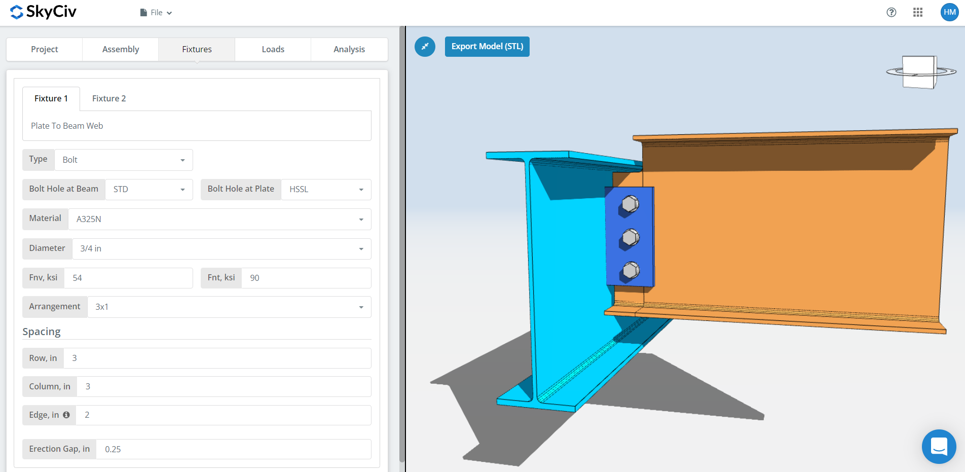
приспособление 1 is the plate to beam web connection. Он может быть скреплен болтами или сварен.; в этом пошаговом руководстве используются болтовые соединения.
Первый, the bolt hole types at the beam and at the plate. Производители обычно просят стандартные отверстия. (ЗППП) in the beam and horizontal short-slotted holes (HSSL) в тарелке, который покупает посадочный допуск в полевых условиях. Note that those two are also the only hole types the conventional configuration permits, so reaching for oversized holes moves you into the extended configuration rules.
следующий, материал или марка болта: А307, А325, A490 или на заказ. A325 и A490 — марки согласно ASTM F3125., который объединил старые автономные спецификации. Выберите N или X для соединения подшипникового типа и SC для критического скольжения..
Соединения, критические к скольжению, имеют меньшую расчетную грузоподъемность болтов, чем подшипниковые., так что используйте их там, где скольжение действительно имеет значение: отверстия увеличенного размера или с прорезями, реверс нагрузки, или усталость. Между N и X, X дает большую способность болта к сдвигу., но резьбы должны быть исключены из плоскости среза, и строитель должен это знать. Между СК(А) и СК(В), СК(В) дает большую емкость и требует более тщательно подготовленной поверхности, например, коммерческая струйная очистка SSPC-SP6.
Тогда диаметр болта, с 5/8″ до 1-1/2″ или метрические эквиваленты, и расположение, вплоть до 12 ряды болтов и столбцы, с расстоянием между строками и столбцами.
Стоит знать: если вам нужна большая вместимость группы болтов, увеличение расстояния может сделать это вместо добавления болтов, as long as the plate height still fits within the beam depth. Прочность группы болтов использует метод мгновенного центра вращения (ИКОР), so a wider spacing is credited with the capacity it actually provides. Сначала обратитесь к производителю, хотя. Многие предпочитают 3″ spacing typical throughout.
В “край” входные данные — расстояние от конца балки до первой колонны болтов..
Последний, эрекция. Это зазор, который позволяет установить балку на место на месте.. Это стоит мощности, поэтому указывайте это только там, где это действительно необходимо для эрекции.
приспособление 2 Вкладка
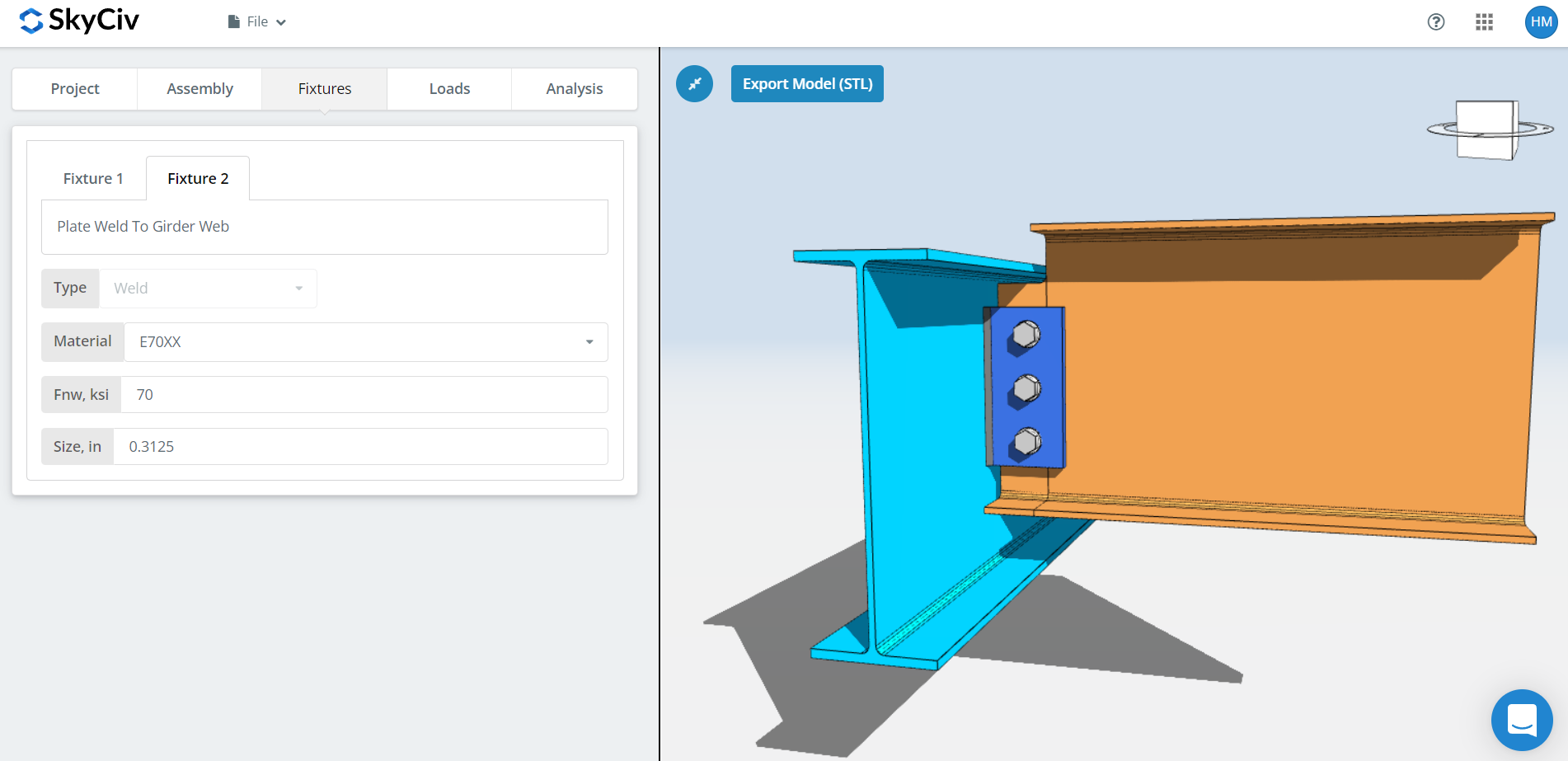
приспособление 2 is the plate to support connection, является ли эта опора балочной перемычкой, полка колонны или стенка колонны. For a single plate this is welded only.
Укажите сварочный материал, или «Пользовательский’ with your own Fnw if the electrode is not listed, тогда размер сварного шва. For single plate connections the weld needs to be at least 5/8 раз больше толщины пластины, so that the weld develops the plate.
That rule has a cost consequence worth planning around. Стол 8-12 15-го издания Руководства AISC, страница 8-126, shows a large jump in weld passes between 5/16″ and 3/8″ филе: 5/16″ needs a single pass, 3/8″ needs three. A 1/2″ plate needs only a 5/16″ fillet to develop it, which keeps you in single-pass territory. So if the connection is short of capacity, increase the plate height to the maximum allowable before you increase the thickness. A thicker plate demands a larger weld, and a larger weld means more passes, more deposited metal and more labour time.
Вкладка "Нагрузки"
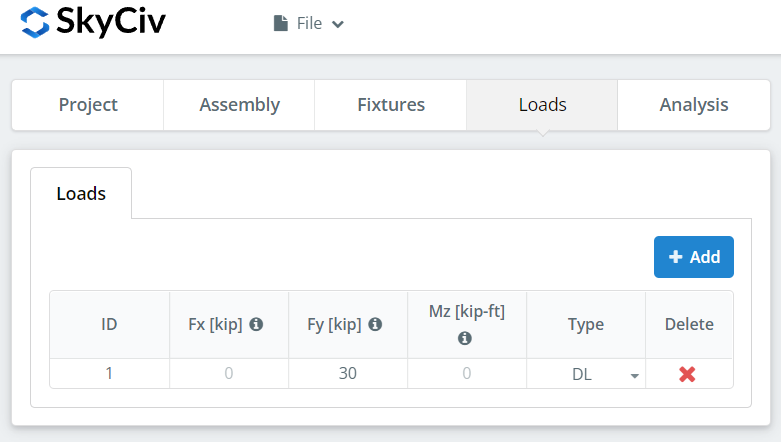
Введите вертикальный сдвиг в поле «Fy»..
Сопоставьте нагрузку с методом расчета, который вы выбрали вначале.. LRFD принимает учтенные нагрузки в зависимости от расчетной прочности; АСД воспринимает эксплуатационные нагрузки в пределах допустимой прочности. Программное обеспечение не может определить, что вы набрали.
Результаты вкладка
Нажмите “Выполнить проверки конструкции”. Все, что отсутствует на предыдущих вкладках, помечается здесь, а не автоматически по умолчанию..
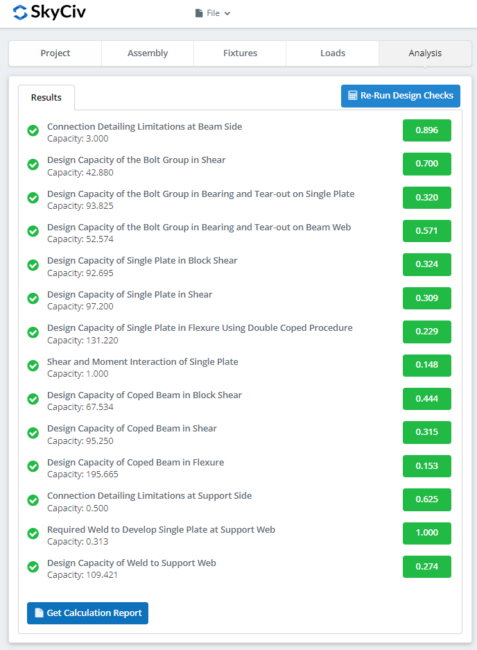
В сводке показано, прошло ли соединение, с коэффициентом использования по каждому чеку. Если это не удалось, измените входные данные на предыдущих вкладках и нажмите “Повторно запустите проверку проекта”. Когда это пройдет, “Посмотреть отчет о расчетах” открывает подробный отчет.
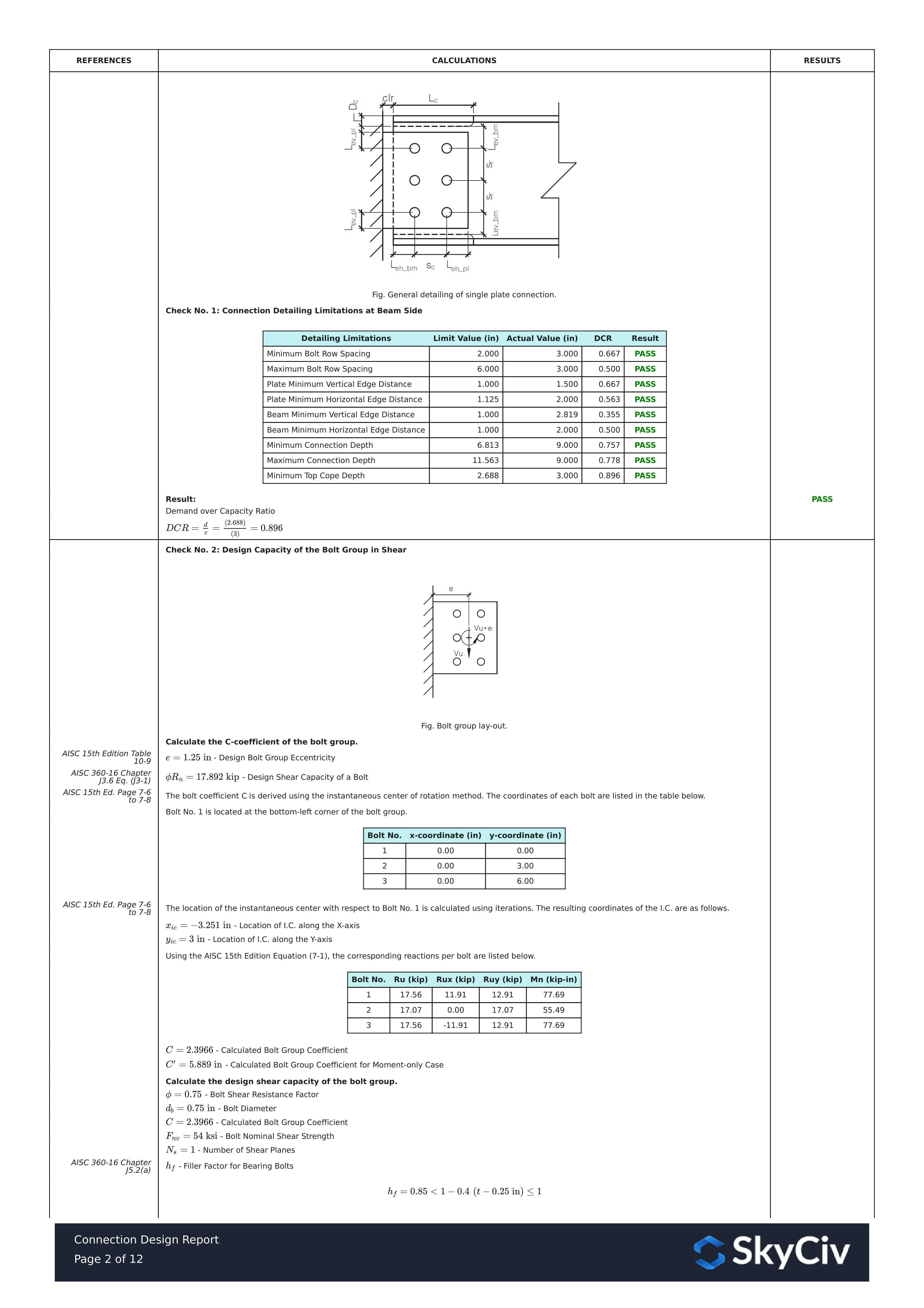
Это выдержка из отчета. Каждая проверка содержит ссылку на руководство или спецификацию AISC., и работа соответствует порядку, используемому в спецификации, поэтому инженер-рецензент может прочитать его построчно вместо того, чтобы перепроектировать число..
Вот PDF-копия полного подробного отчета о расчетах: Отчет о конструкции соединения.
Попробуйте сами
Pick the single plate, введите свои разделы, plate and shear, и просматривать каждую проверку со ссылкой на код. Он запускается в браузере, нечего устанавливать.
См. также single plate connection calculator, в double angle calculator, и соединения сдвига обзор.
