
Что такое моментная связь?
Моментное соединение – это соединение, передающее изгибающий момент between a beam and a column, или между любыми двумя членами, as well as shear. Если балка несет на своем конце внутренний момент, соединение должно переносить этот момент через соединение, а не позволять концу свободно вращаться.. Moment connections are also called rigid or fixed connections, and in a steel frame they are what makes a moment frame work.
Aisc 360-16 Section B3.4 splits them in two. А полностью сдержанный (фр.) moment connection holds the angle between the members, which justifies modelling the joint as fixed. А частично сдержанный (пиар) connection transfers moment but rotates enough that the analysis has to account for the joint’s real stiffness. Если рассматривать соединение PR как полностью жесткое, то это преувеличивает жесткость рамы и занижает ее смещение..
Цель момент связи заключается в удержании конечного вращения, что с точки зрения анализа является код фиксации FFFFFF: сдержан во всех трех перемещениях и всех трех вращениях.
Где сдвиговое соединение работает в основном через лучевое полотно, моментное соединение должно зацепляться с фланцами, потому что именно здесь возникает изгибающее напряжение. Фланцевые пластины, welded flanges and end plates all do the same job. They turn the beam’s moment into a tension force in one flange and a compression force in the other, и неси эту парочку в колонну. The column then has to take two concentrated forces on its flange, which is why moment connection design always ends with checks on the column itself.
This page sets out the moment connection design procedure with the AISC 360-16 and Design Guide 39 уравнения, and links to three fully worked AISC calc sheet examples: a flush end plate, an extended end plate and a bolted flange plate. SkyCiv Connection Design checks moment connections to Aisc 360-16 как в ASD, так и в LRFD.
Types of Moment Connections
Моментные соединения несут гораздо больший момент, чем сдвиговые соединения., и их изготовление обходится дороже: больше материала, больше сварки, больше подгонки и больше проверок. Большинство рам используют их только там, где конструкция опирается на действие рамы для обеспечения поперечной устойчивости., и везде используйте сдвиговые соединения.
Какие конфигурации доступны, зависит от проектного кода и от того, какой каркас балки..
Балка к двутавровой колонне (Aisc 360-16)
Четыре конфигурации, каркас к полке колонны или к стенке колонны:
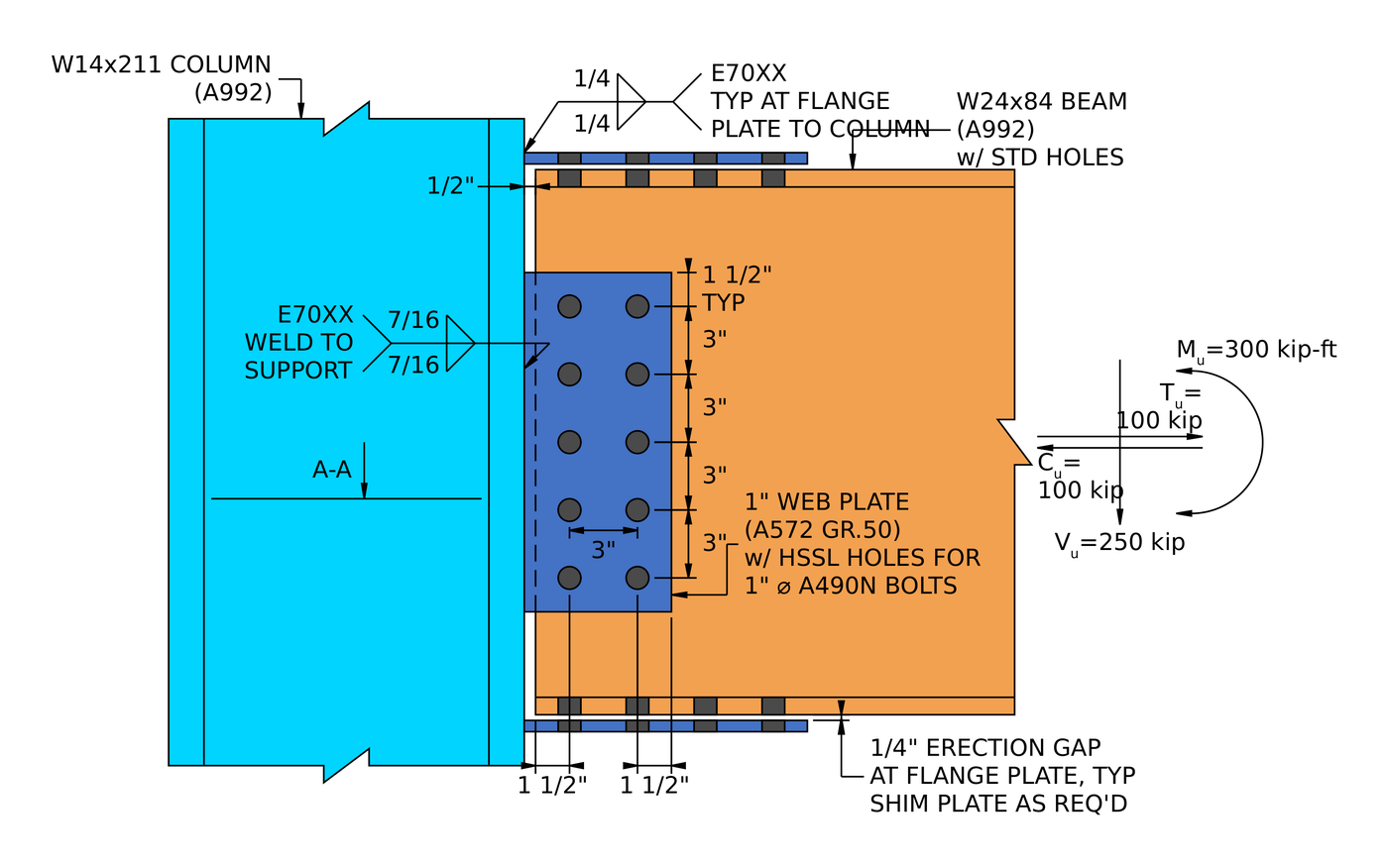
- Фланцевая пластина. Plates at the top and bottom flanges of the beam, shop-welded to the column and field-bolted to the beam. Когда луч изгибается, одна пластина переходит в растяжение, а другая в сжатие., и эта пара хранит в себе момент. A separate web plate, in effect a shear tab, carries the shear. All the welding happens in the shop, which is why fabricators like it (worked example).
- Приварные фланцы. The beam flanges are welded straight to the column flange with no intermediate plate, и перемычка прикреплена болтами к срезной пластине. Это обеспечивает самое жесткое соединение в группе и самый чистый путь нагрузки., но это сварка элемента, который должен соответствовать допускам., поэтому он осуществляет предварительный нагрев, затраты на доступ и осмотр, которых не требует болтовая деталь.
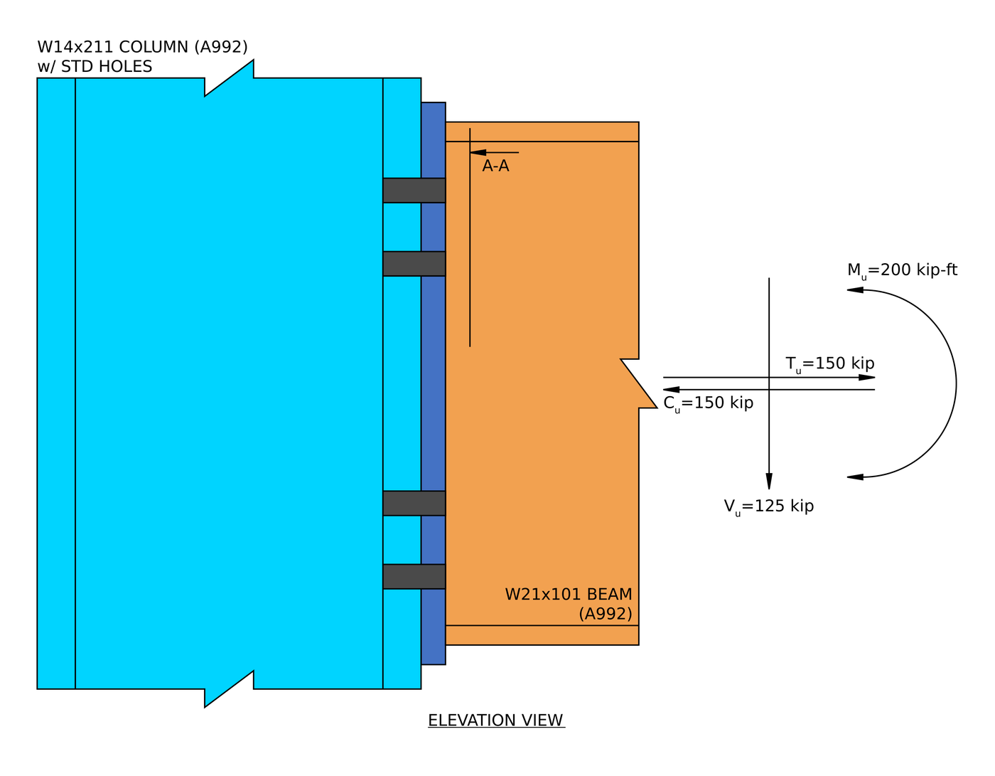
- Торцевая пластина заподлицо. Пластина, приваренная к концу балки и прикрепленная болтами к колонне., finishing flush with the beam flanges so all bolts sit between them. It stays within the beam depth, which suits floors, but the bolts’ lever arm is limited, так что это подходит для умеренных моментов (worked example).
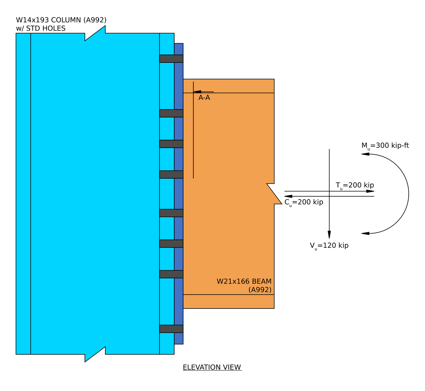
- Удлиненная концевая пластина. Та же идея, with the plate extended past the tension flange so a bolt row can sit outside it. That row has the longest lever arm about the compression flange, and the extension adds yield lines to the plate, это то, что покупает дополнительный момент мощности. Это конфигурация, показанная вверху этой страницы. (worked example).
Балка к колонне HSS (Aisc 360-16)
Создать моментное соединение в полой секции сложнее., потому что нет фланца, через который можно было бы провернуть болты, и нет доступа к дальней стороне. Доступна одна конфигурация: а фланцевая пластина приваривается к лицевой стороне HSS, без ребер жесткости.
КАК 4100:2020
КАК 4100 в SkyCiv Connection Design охватываются только сдвиговые соединения., каркасная балка к двутавровой колонне или балка к балке. Моментальные подключения к AS 4100 недоступны. Для моментного дизайна, использовать AISC 360-16.
How to design a moment connection to AISC 360-16
Every moment connection is designed by following the flange force. The beam moment becomes a tension force in one flange and a compression force in the other. Each force passes from the beam flange, through the bolts, plates or welds, into the column flange, and the column has to carry it. The shear goes through the web separately. A failure anywhere along either path is a failure of the connection.
The equations below are the LRFD forms from AISC 360-16, the AISC Manual 15th Edition and, for end plates, Руководство по проектированию AISC 39. Для РАС, replace [mathin] \phi R_{n} [mathin] с участием [mathin] R_{n} / \Omega [mathin], API рендерера SkyCiv [mathin] \Omega [mathin] given in the same clause ([mathin] \Omega = 2.00 [mathin] где [mathin] \phi = 0.75 [mathin], и [mathin] \Omega = 1.67 [mathin] где [mathin] \phi = 0.90 [mathin]).
1. The flange force
The moment is carried as a couple. Dividing it by the distance between the flange centroids gives the force in each flange, and an axial load adds half its value to each flange:
[math] P_{uf} = \frac{M_{u}}{d – t_{f}} + \frac{P_{u}}{2} [math]
In the flange plate example, а 300 kip-ft moment on a W24x84 with 100 kip of axial load gives [mathin] P_{uf} = 204.31\,kip [mathin], and every check on the flange plates is made against that one number.
End plates work the same way, but Design Guide 39 rolls the axial tension into an equivalent moment, because it pulls on the same tension bolts:
[math] M_{u,eq} = M_{u} + \frac{T_{u}}{2} \left( d – t_{f} \right) [math]
This is not a small correction. In the flush end plate example, 150 kip of tension turns a 200 kip-ft moment into 328.75 Вы можете заметить, что основное отличие заключается в соединении полок балки с опорной колонной..
2. Детализация лимитов (J2.2b, J3.3, J3.4, J3.5)
Перед любой проверкой прочности, the connection has to be buildable. Bolts need a minimum spacing and edge distance, a wrench needs room to turn, and fillet welds need a minimum size for the parts they join (Таблица J2.4). Минимальное расстояние между болтами составляет:
[math] s_{min} = 2\tfrac{2}{3}\, d_{b} \qquad (3\, d_{b}\ \text{preferred}) [math]
An end plate also has to be deep enough past each flange for the flange weld to fit. In the extended end plate example the bolt column spacing sits exactly on the minimum, соотношение 1.000, что разрешено. Designers lay bolts out at the limits to keep the plate small.
3. Торцевые пластины: bolt size and plate thickness (Руководство по проектированию 39)
Руководство по проектированию 39 uses a thick plate approach. The bolts are sized to reach their tensile strength with no prying, and then the plate is made stiff enough that prying never develops. The bolt diameter comes from the lever arms [mathin] h_{i} [mathin] of the tension bolt rows about the centre of the compression flange:
[math] d_{b,reqd} = \sqrt{\frac{4\, M_{u,eq}}{\pi\, \phi\, F_{nt} \sum_{i} n_{i} h_{i}}}, \qquad \phi = 0.75 [math]
The plate’s bending strength comes from a yield line pattern around those bolts, summarised in the yield line parameter [mathin] Y_{p} [mathin] from the guide’s tables for each bolt pattern:
[math] t_{p,reqd} = \sqrt{\frac{1.10\, M_{u,eq}}{\gamma_{r}\, \phi\, F_{yp}\, Y_{p}}}, \qquad \phi = 0.90 [math]
В 1.10 factor keeps the plate 10% stronger than the demand, so it stays stiff and the no-prying assumption holds. [mathin] \gamma_{r} [mathin] является 1.0 for an extended plate and 0.8 для панели смыва, because a flush plate is more flexible and has to be made thicker to count as fully restrained. The extension is where the extra strength comes from: the extended example has [mathin] Y_{p} = 212.35\,in [mathin], против 123.54 in for the flush plate.
4. Фланцевые пластины: соскальзывать, bearing and block shear (J3.8, J3.10, J4.3)
Flange plates are often detailed with oversized holes for fit-up, and J3.2 allows those only in slip-critical joints. The slip resistance of the bolt group is:
[math] \phi R_{n} = \phi\, \mu\, D_{u}\, h_{f}\, T_{b}\, N_{s}\, n_{b} [math]
где [mathin] \mu = 0.5 [mathin] for Class B surfaces, [mathin] D_{u} = 1.13 [mathin], [mathin] T_{b} [mathin] is the minimum bolt pretension from Table J3.1, и [mathin] h_{f} [mathin] это коэффициент наполнителя, 0.85 when there may be two or more fillers. [mathin] \phi = 0.85 [mathin] для негабаритных отверстий. In the flange plate example slip is checked at 0.978.
Bolt bearing and tear-out follow J3.10 on both the plate and the beam flange:
[math] \phi r_{n} = \phi\, \min\left( 1.2\, l_{c}\, t\, F_{u},\ 2.4\, d_{b}\, t\, F_{u} \right), \qquad \phi = 0.75 [math]
and the plate and the beam flange are each checked for block shear tearing out around the bolts:
[math] \phi R_{n} = \phi \left( 0.6\, F_{u} A_{nv} + U_{bs} F_{u} A_{nt} \right) \le \phi \left( 0.6\, F_{y} A_{gv} + U_{bs} F_{u} A_{nt} \right), \qquad \phi = 0.75 [math]
Try bolt layouts in the калькулятор болтов.
5. Flange plates in tension and compression (J4.1, J4.4)
The tension plate is checked for yielding on the gross section and rupture through the holes:
[math] \phi R_{n} = \min\left( 0.90\, F_{y} A_{g},\ 0.75\, F_{u} A_{e} \right) [math]
The compression plate is a short column between the column face and the first bolt row. Если он достаточно коренастый, J4.4 lets you skip the Chapter E buckling equations:
[math] \frac{K L}{r} \le 25 \quad \Rightarrow \quad \phi R_{n} = 0.90\, F_{y}\, A_{g} [math]
For a plate, [mathin] r = t / \sqrt{12} [mathin], so a thin plate reaches the limit quickly. В 1/2 in plate in the flange plate example comes in at 24.942, just under 25.
6. The beam at the bolt holes (Д3, Ф13.1)
The holes come out of the beam’s tension flange at exactly the point of maximum moment. F13.1 checks whether they reduce the beam’s flexural strength:
[math] F_{u} A_{fn} \lt Y_{t} F_{y} A_{fg} \quad \Rightarrow \quad M_{n} = \frac{F_{u} A_{fn}}{A_{fg}}\, S_{x} [math]
[mathin] Y_{t} = 1.0 [mathin] когда [mathin] F_{y}/F_{u} \le 0.8 [mathin]. The flange force also has to get into the beam: half the beam, a tee, is treated as a tension member connected through the flange only, with shear lag reducing the net area:
[math] U = 1 – \frac{\bar{y}}{l} [math]
7. Welds and the base metal (Дж2.4, Ручное уравнение. 9-2)
The flange force crosses a weld in every one of these connections: фланцевая пластина к колонне, or beam flange to end plate. Loaded perpendicular to its length, a fillet weld gets the J2.4 directional increase of 1.5:
[math] \phi R_{n} = \phi\, 0.6\, F_{EXX}\, \frac{\sqrt{2}}{2}\, w\, L_{w} \left( 1 + 0.5\, \sin^{1.5}\theta \right), \qquad \phi = 0.75 [math]
The steel on either side limits how much of the weld size counts. For welds on both faces of a part of thickness t, the usable size in sixteenths is:
[math] D_{max} = \frac{ \frac{t}{2}\, F_{u} }{3.09\,kip/in} [math]
Руководство по проектированию 39 adds a floor to the end plate flange welds: they are designed for at least 60% предела текучести фланца, so the weld is never the weak link even under a small moment.
[math] P_{fl} \ge 0.6\, F_{y}\, b_{f}\, t_{f} [math]
In the flush example the floor (295.2 кип ) is higher than the force from the loads (191.5 кип ), so the floor sizes the weld. In the flange plate example the 1/4 in weld to the column governs the whole connection at 0.998. Try sizes in the сварочный калькулятор.
8. Shear through the web
The beam shear does not go through the flanges. In a flange plate connection it goes through the web plate, which is designed like a shear tab: срез болта, bearing on the plate and the beam web, сдвиг блока, and shear yielding and rupture of the plate. In the flange plate example, shear rupture of the 1 in web plate governs that side at 0.943.
In an end plate, the shear goes through the web welds outside the tension zone, and the beam web often limits the weld. In the flush end plate example the 1/2 in web limits the usable weld size to 0.3287 в, меньше, чем 3/8 в указанном, and the web weld in shear governs the connection at 0.988.
9. The column: flange bending, web yielding, crippling and panel zone (J10)
The flange forces arrive at the column as concentrated loads, and the column has to carry them without local failure. These checks decide whether the column needs transverse stiffeners or a web doubler plate, and they are often cheaper to satisfy with a heavier column than with stiffeners.
Местный изгиб фланца, under the tension flange (уравнение. J10-1):
[math] \phi R_{n} = \phi\, 6.25\, F_{y}\, t_{f}^{2}, \qquad \phi = 0.90 [math]
Локальный веб-выход, with bearing length [mathin] l_{b} [mathin], away from the column end (уравнение. J10-2):
[math] \phi R_{n} = \phi\, F_{y}\, t_{w} \left( 5k + l_{b} \right), \qquad \phi = 1.00 [math]
Руководство по проектированию 39 uses 6k in place of 5k for end plates, because the force spreads through the plate before it reaches the column.
Web crippling, under the compression flange (уравнение. J10-4):
[math] \phi R_{n} = \phi\, 0.80\, t_{w}^{2} \left[ 1 + 3 \left( \frac{l_{b}}{d} \right) \left( \frac{t_{w}}{t_{f}} \right)^{1.5} \right] \sqrt{\frac{E\, F_{y}\, t_{f}}{t_{w}}}\, Q_{f}, \qquad \phi = 0.75 [math]
Сдвиг полотна зоны панели, where the column web between the flange forces is in shear (уравнение. J10-9):
[math] \phi R_{n} = \phi\, 0.60\, F_{y}\, d_{c}\, t_{w}, \qquad \phi = 0.90 [math]
For end plates, the tension bolts also bend the column flange into a yield line pattern, checked like the end plate itself:
[math] \phi M_{cf} = \phi\, F_{y}\, t_{f}^{2}\, Y_{c} \ge 1.10\, M_{u,eq} [math]
Panel zone shear governed the column in all three worked examples, в 0.461, 0.726 и 0.492. A failing panel zone needs a doubler plate, and a failing flange or web check needs stiffeners opposite the beam flange.
Moment connection design examples (Aisc 360-16 LRFD)
Each example below is a full AISC calc sheet from SkyCiv Connection Design, written out step by step with every equation, substituted value and DCR.
| пример | Members and load | Связь | Governing check |
|---|---|---|---|
| Заподлицо с торцевой пластиной | W21x101 beam to W14x211 column flange; 200 Вы можете заметить, что основное отличие заключается в соединении полок балки с опорной колонной., 125 кип сдвиг, 150 kip axial | 1 в А572 гр. 50 торцевая пластина, eight 1 в болтах А490-Н | Web weld in shear, 0.988, with the end plate thickness just behind |
| Extended end plate | W21x166 beam to W14x193 column flange; 300 Вы можете заметить, что основное отличие заключается в соединении полок балки с опорной колонной., 120 кип сдвиг, 200 kip axial | 7/8 в А572 гр. 50 торцевая пластина, 3/4 in A325-N bolts in the four-wide/two-wide pattern | Фланцевая сварка, 0.931, then the plate thickness at 0.927 and bolt size at 0.923 |
| Фланцевая пластина | W24x84 beam to W14x211 column flange; 300 Вы можете заметить, что основное отличие заключается в соединении полок балки с опорной колонной., 250 кип сдвиг, 100 kip axial | 1/2 in flange plates with eight 1 in A490-SC bolts each, 1 in web plate with ten 1 в А490-Н | Flange plate weld to the column, 0.998, then bolt slip at 0.978 |
The pattern is worth knowing. In an end plate, the bolts and the plate are sized together and tend to finish close to each other, and the beam web often limits the welds. In a flange plate, everything on the flange side is checked against the same flange force, so the welds and the slip-critical bolts end up working equally hard. In all three, the column needed no stiffeners or doubler plate, but the panel zone was the column check closest to its limit.
For the theory behind the examples, видеть design of steel connections using AISC 360-16.
Which moment connection should you use?
| Связь | Best for | Watch for |
|---|---|---|
| Фланцевая пластина | All shop welding, all field bolting, and erection tolerance at the flanges | Slip-critical bolts in oversized holes, shims and filler factors, and the plate weld to the column |
| Welded flanges | The stiffest joint and the shortest load path | Field welding, preheat, access and inspection |
| Заподлицо с торцевой пластиной | Moderate moments where nothing can project past the beam, for example under a slab | Short bolt lever arms, в 0.8 reduction on the plate, and the beam web limiting the welds |
| Extended end plate | Larger moments with fast, all-bolted field erection | Accurate beam length, благодаря таблицам расчета, предлагаемым в AISC, and column flange bending at the tension bolts |
Что проверяет программа?
Детализация выполняется в первую очередь: Расстояние до края болта, расстояние между болтами (шаг и калибр), зазоры между инструментами, минимальные и максимальные размеры пластины, minimum weld sizes, и обнаружение столкновений между пластинами, ребра жесткости, болты и сварные швы. Соединение, которое невозможно построить, не доходит до решения.
The strength checks then follow the procedure above. For end plates that means the required bolt diameter and plate thickness from Design Guide 39, the extended portion of the plate in shear, the flange and web welds with their base metal, and bolt shear, подшипник и отрыв. For flange plates it means slip, несущий, сдвиг блока, plate tension and compression, beam rupture at the holes and the welds, plus the web plate as a shear tab. On the column it means flange bending, локальный веб-выход, паутина наносит вред, выпучивание стенки при сжатии и сдвиг в зоне панели.
Каждая формула, проверка конструкции и ссылка на код показаны полностью, с номерами статей от AISC 360-16, чтобы вы могли следить за расчетом, а не принимать его на веру. The worked examples above are written from those reports. For the fastener side, см. документацию по болты и сварные швы.
Моментное соединение против сдвигового соединения: различия
Разница в том, что происходит с углом между двумя элементами.. В мгновение ока этот угол удерживается, поэтому изгиб одного члена влечет за собой другой. При сдвиговом соединении соединение может свободно вращаться., поэтому конец балки поворачивается, и никакой значимый момент не пересекает соединение. Видеть what is a shear connection for the other half of the comparison.
| Момент соединения | Срезное соединение | |
|---|---|---|
| Переданные силы | Сдвиг и момент | Только сдвиг |
| Альтернативные названия | Жесткий, Зафиксированный, Момент-сопротивляющийся | Закреплено, Петля, просто |
| Aisc 360-16 срок | Моментное соединение FR или PR | Простое подключение |
| вращение | Ограничивает вращение | Свободно вращаться |
| Код исправления программного обеспечения | FFFFFF | FFFFFR |
Часто задаваемые вопросы
How do you calculate the flange force in a moment connection?
Divide the beam end moment by the distance between the flange centroids, [mathin] d – t_{f} [mathin], and add half of any axial load. А 300 kip-ft moment on a W24x84 (d = 24.1 в, Tе знак равно 0.77 в) с участием 100 kip of axial load gives 204.31 kip in each flange.
What is the difference between a fully restrained and a partially restrained moment connection?
A fully restrained (фр.) connection holds the angle between the members, so the frame can be analysed with a fixed joint. A partially restrained (пиар) connection transfers moment but rotates noticeably, so its rotational stiffness has to go into the analysis. Aisc 360-16 B3.4 defines both. В 0.8 reduction factor on flush end plates in Design Guide 39 exists to keep those connections stiff enough to be treated as FR.
When does a moment connection need column stiffeners or a doubler plate?
When the column fails one of the J10 checks under the flange forces. Местный изгиб фланца, локальный веб-выход, web crippling and web compression buckling are fixed with transverse stiffeners opposite the beam flanges. Panel zone shear is fixed with a doubler plate on the column web. Often a heavier column section is cheaper than either, because stiffeners and doublers add welding.
What is the difference between a flush and an extended end plate?
Торцевая пластина заподлицо останавливается на полках балки., so all the bolts are between them. Удлиненная торцевая пластина выступает за натяжной фланец, а снаружи находится ряд болтов.. That row has the longest lever arm, и расширение добавляет линии доходности, поэтому расширенная пластина несет гораздо больший момент. A flush plate is used where the connection has to stay within the beam depth.
Why are flange plate bolts slip-critical?
Flange plates are usually detailed with oversized holes, to give the erector tolerance at the flanges, и AISC 360-16 J3.2 допускает отверстия увеличенного размера только в соединениях, критичных к скольжению.. The bolts are pretensioned and the faying surfaces prepared, typically to Class B, so the joint carries the flange force by friction.
Can I design a moment connection with ASD instead of LRFD?
да. The limit states are the same. Replace [mathin] \phi R_{n} [mathin] с участием [mathin] R_{n} / \Omega [mathin] and compare against the ASD loads. SkyCiv Connection Design runs both, and switching between them is one setting.
Do the examples follow the AISC 15th or 16th edition Manual?
They follow AISC 360-16 with the AISC Manual 15th Edition, который написан вокруг этой спецификации, и Руководство по проектированию AISC 39 for the end plates. The 16th Edition Manual pairs with AISC 360-22. The limit states are much the same, but clause and table references move, поэтому проверьте их на соответствие версии, которую использует ваш проект..
Программное обеспечение SkyCiv Connection Design
Модели и проверки выше взяты из SkyCiv Connection Design. Он охватывает более 80+ предварительно настроенные типы подключения, проекты по стандарту AISC 360-16 (LRFD & ASD) и, как 4100:2020, и показывает каждую формулу, проверка конструкции и полная ссылка на код.
Вы можете смоделировать соединение в 3D., поменять болты, сварные швы или пластины без потери данных о нагрузке, создавать листы 2D-детальных чертежей в CloudCAD, и экспортируйте 3D-геометрию в IFC для координации в Revit., Текла или Navisworks.
Он работает полностью в браузере, без загрузок, обновления или настройка ИТ.
The full module adds the step-by-step calculation report, like the worked examples above, with every capacity and DCR.
Ссылки
- Aisc 360-16, Спецификация для зданий из конструкционной стали: Б3.4, Д3 (Таблица D3.1), Ф13.1 (уравнение. Ф13-1), J2.2b (Таблица J2.4), Дж2.4, J3.1 (Таблица J3.1), J3.2, J3.3, J3.4, J3.5, J3.6, J3.8, J3.10, J4.1, J4.3, J4.4 (уравнение. J4-6), J10 (уравнение. J10-1, J10-2, J10-4, J10-8, J10-9).
- Руководство по стальным конструкциям AISC, 15й выпуск: Часть 9 (уравнение. 9-2, base metal limit on weld size); Часть 12 (fully restrained moment connections).
- Руководство по проектированию AISC 39, Моментные соединения торцевой пластины.

Гарольд Муналем
Менеджер по продукту, Дизайн подключения
10+ лет в проектировании стальных соединений
LinkedIn

