
Что такое соединение сдвига?
Срезное соединение — это соединение, которое передает поперечную силу между двумя элементами без передачи значимого момента.. Если луч несет внутреннюю сдвигающая сила, эта сила проходит через соединение в опорную колонну как осевая сила. Срезные соединения ведут себя как штифт. (FFFFFR в SkyCiv Structural 3D), в отличие от момент соединения, которые удерживают конечное вращение.
В АИСК 360-16 с точки зрения это также доступны под связь (Б3.4): предполагается, что он свободно вращается и испытывает незначительный момент.. КАК 4100:2020 называет эквивалентную схему простой конструкцией. Полужесткое соединение — третий случай., с реальной, но частичной вращательной жесткостью, и это нужно моделировать таким образом, а не рассматривать как простое.
Пластина или угол передает силу между двумя элементами.. В примере выше, любая направленная вниз нагрузка на балку передается на опорный элемент через угол. Потому что ничто не сдерживает полки балки, сустав может вращаться, именно это делает соединение сдвиговым, а не моментным..
Соединения, работающие на сдвиг являются наиболее распространенным соединением в стальном каркасе.. Где закреплена рама, крепление обеспечивает боковую устойчивость, поэтому моментные связи нужны только там, где фрейм полагается на действие фрейма. Вот почему большинство проектировщиков стремятся к сдвиговому соединению везде, где это позволяет расчет.: их проще изготовить и дешевле возвести.
Shear connection design comes down to following the beam reaction from the beam web, through the bolts, plate or angle and welds, into the support, and checking every part it passes through. This page sets out that procedure with the AISC 360-16 уравнения, and links to five fully worked AISC calc sheet examples that apply it to real connections.
SkyCiv Connection Design проверяет сдвиговые соединения на Aisc 360-16 как в ASD, так и в LRFD, и чтобы КАК 4100:2020.
Типы сдвиговых соединений
Сдвиговые соединения названы в честь компонента, несущего нагрузку, и места его расположения.. Какие из них доступны, зависит от проектного кода и от того, какой каркас балки., поэтому списки ниже разделены таким образом.
Балка к двутавровой колонне, или луч к лучу (Aisc 360-16)
Шесть конфигураций, каждого доступного каркаса до полки колонны, к сетке колонны, или луч-луч через сеть:
- Единый угол. Один Г-образный кронштейн между стенкой балки и опорой. Самый легкий вариант, и самый гибкий, поэтому он подходит для легких нагрузок. The reaction sits off the support-side bolt line, so those bolts carry an eccentricity (worked example).
- Двойной угол. Углы на обеих сторонах стенки балки. The extra angle puts the beam-side bolts in double shear and makes the connection more forgiving during erection, вот почему это рабочая лошадка для более тяжелых балок (worked example).
- Одиночная плита. Вкладка «Срез». Одна тарелка, приварены к опоре и прикреплены болтами к стенке балки. Обычно самый дешевый из группы, потому что есть одна линия сварки и одна группа болтов (worked example). When the plate has to reach past the column flanges into a column web, it becomes an extended single plate, which is designed differently (worked example).
- Двойная пластина. Пластины на обеих сторонах полотна, используется там, где одна пластина не может выдержать срез или соответствовать требуемой группе болтов..
- Торцевая пластина. Пластина, приваренная к концу балки и прикрепленная болтами к опоре.. Необходимо, чтобы балка была точно отрезана по длине., так как пластина не оставляет регулировки (worked example).
- Непосредственно сваренная паутина. Стенка балки приварена прямо к опоре, без промежуточной пластины и уголка. Нет болтов, которые можно было бы проверить., но он требует сварки в полевых условиях и теряет допуск на монтаж, который обеспечивает деталь с болтовым соединением..
Балка к колонне HSS (Aisc 360-16)
Обрамление полой секции меняет то, что подходит, потому что нет фланца, к которому можно было бы прикрутить болты, и нет доступа к дальней стороне для гаечного ключа.. Доступны пять конфигураций:
- Единый угол и Двойной угол
- Одиночная плита
- Одноместный WT. Тройник, вырезанный из широкого фланца, его стержень приварен или прикреплен болтами к стенке балки, а полка - к грани колонны..
- Угол сиденья. Угол под нижней полкой, несущий балку в опоре, обычно с верхним зажимом для устойчивости. В отличие от типов, подключенных к Интернету, этот работает вне фланца.
КАК 4100:2020
Австралийский кодекс охватывает каркас балки-двутавровой колонны и балки-балки., с четырьмя конфигурациями:
- Боковая пластина паутины, АС 4100 название вкладки сдвига.
- Гибкая торцевая пластина
- Единый угол и Двойной угол
КАК 4100 покрытие только сдвиговое, и не распространяется на столбцы HSS, каналы, распорки или соединения. это АЙСК 360-16.
How to design a shear connection to AISC 360-16
Every shear connection is designed the same way: take the factored beam end reaction, [mathin] R_{u} [mathin] (или [mathin] R_{a} [mathin] for ASD), and check each part of the load path against it. The reaction leaves the beam web, passes through the beam-side bolts or welds into the plate or angles, and then through the support-side bolts or welds into the column or girder. A failure anywhere along that path is a failure of the connection.
The equations below are the LRFD forms from AISC 360-16 и Руководство AISC, 15-е издание.. Для РАС, replace [mathin] \phi R_{n} [mathin] с участием [mathin] R_{n} / \Omega [mathin], API рендерера SkyCiv [mathin] \Omega [mathin] given in the same clause ([mathin] \Omega = 2.00 [mathin] где [mathin] \phi = 0.75 [mathin], и [mathin] \Omega = 1.50 [mathin] где [mathin] \phi = 1.00 [mathin]).
1. Детализация лимитов (J3.3, J3.4)
Перед любой проверкой прочности, the geometry has to be buildable and match the assumptions behind the strength equations. Bolts need a minimum spacing and edge distance, a wrench needs room to turn, and the plate or angle should be at least half the beam’s T dimension deep so the beam end stays stable. Минимальное расстояние между болтами составляет:
[math] s_{min} = 2\tfrac{2}{3}\, d_{b} \qquad (3\, d_{b}\ \text{preferred}) [math]
Minimum edge distances come from Table J3.4, with an increment from Table J3.5 when the edge is measured across a slotted hole. In the worked examples a detailing limit is often the highest ratio in the whole connection. That is normal: designers lay the bolts out at the limits to keep the plate small.
2. Bolt shear and eccentricity (J3.6, Ручная часть 7)
The strength of one bolt in shear is:
[math] \phi r_{v} = \phi\, F_{nv}\, A_{b}\, N_{s} = \phi\, F_{nv}\, \frac{\pi}{4} d_{b}^{2}\, N_{s}, \qquad \phi = 0.75 [math]
где [mathin] F_{nv} [mathin] comes from Table J3.2 (54 ksi for A325-N and 68 ksi for A490-N, grades within ASTM F3125) и [mathin] N_{s} [mathin] is the number of shear planes. The bolts in a double angle beam-side group are in double shear, [mathin] N_{s} = 2 [mathin].
The reaction rarely acts on the bolt line. When it sits a distance e away, the bolts carry a moment [mathin] R_{u}\, e [mathin] as well as the shear, and the group delivers fewer than n bolts’ ценность силы. Мгновенный центр вращения (ИКОР) method finds that reduced count, the coefficient C, from the load-deformation curve of each bolt (Ручное уравнение. 7-1):
[math] R = R_{ult} \left( 1 – e^{-10\Delta} \right)^{0.55} [math]
[math] \phi R_{n} = C\, \phi r_{v} [math]
How much eccentricity to design for depends on the connection type, and this is where the five worked examples differ most:
| Связь | Эксцентричность дизайна | Effect in the worked example |
|---|---|---|
| Одиночная пластина (conventional) | [mathin] e = a/2 [mathin] from Manual Table 10-9 | 2 in to the bolt line becomes e = 1 в; three bolts give C = 2.71 |
| Extended single plate | Full distance from the weld to the bolt group | е = 10.25 in cuts 14 прикручивается к 6.29 effective bolts |
| Один угол, сторона поддержки | [mathin] e = g + t_{w}/2 [mathin], from the support bolt line to the middle of the beam web | е = 1.85 in cuts 2 прикручивается к 1.24 болты’ worth |
| Двойной угол, сторона балки | Neglected (Ручная часть 10) | The bolt group is treated as concentric |
For the iteration itself, видеть расчет группы болтов с помощью ICOR, or run a bolt group in the калькулятор болтов.
3. Подшипник болта и вырыв (J3.10)
Each bolt pushes on the edge of its hole. The ply either crushes locally around the hole (несущий) or tears a strip out to the next hole or the edge (вырыв). With deformation at service load a design consideration:
[math] \phi r_{n} = \phi\, \min\left( 1.2\, l_{c}\, t\, F_{u},\ 2.4\, d_{b}\, t\, F_{u} \right), \qquad \phi = 0.75 [math]
[math] l_{c1} = L_{e} – \frac{d_{h}}{2} \qquad l_{c2} = s – d_{h} [math]
The edge bolt has the short clear distance [mathin] l_{c1} [mathin], so tear-out usually limits it, while the inner bolts reach the 2.4 d t FU крышка подшипника. Check every ply: the plate or angles, and the beam web. A thin beam web is often the weak ply, because the angles or plate are sized independently. In the double angle example the two 1/4 in angles give 0.5 in of steel against the bolts, но 1/4 in beam web has only one ply, and bearing on the web is the highest strength ratio, в 0.760.
Each bolt then delivers the least of its shear, bearing and tear-out strengths, а сила группы равна сумме (J3.6 Комментарий):
[math] \phi R_{n,eff} = \frac{C}{n} \sum_{i=1}^{n} \min\left( \phi r_{v},\ \phi r_{n,plate,i},\ \phi r_{n,web,i} \right) [math]
4. Блок сдвиг (J4.3)
A block of the plate, angle or coped beam web can tear out around the bolt group: shear along the line of holes plus tension across to the free edge, usually an L-shaped block.
[math] \phi R_{n} = \phi \left( 0.6\, F_{u} A_{nv} + U_{bs} F_{u} A_{nt} \right) \le \phi \left( 0.6\, F_{y} A_{gv} + U_{bs} F_{u} A_{nt} \right), \qquad \phi = 0.75 [math]
[mathin] U_{bs} = 1 [mathin] when the tension stress is uniform, which is the case for a single line of bolts. The net areas deduct each hole at [mathin] d_{h} + 1/16\,in [mathin] for damage during punching (Б4.3). In the shear end plate example, block shear of the plate is the second highest ratio, в 0.920.
5. Shear yielding and shear rupture (J4.2)
The plate or angles carry the whole reaction in shear, across the gross section (уступчивость) и по сечению сетки через отверстия (разрыв):
[math] \phi R_{n} = \phi\, 0.6\, F_{y}\, A_{gv}, \qquad \phi = 1.00 [math]
[math] \phi R_{n} = \phi\, 0.6\, F_{u}\, A_{nv}, \qquad \phi = 0.75 [math]
In the single plate example, shear rupture of the 1/2 in plate is the highest load check, в 0.629.
6. Plate flexure and the shear-flexure interaction
The reaction acts at a distance from the support, so a single plate is a short cantilever. SkyCiv checks it with the Manual’s double-coped beam procedure, which treats the plate like a beam web coped top and bottom, and checks flexural rupture on the net section through the holes. Because the same section carries shear and moment, the two combine:
[math] \left( \frac{V_{u}}{\phi V_{n}} \right)^{2} + \left( \frac{V_{u}}{\phi R_{n}} \right)^{2} \le 1.0 [math]
This check grows with the eccentricity. In the conventional shear tab it is minor, but in the extended single plate example the rupture interaction governs the connection at 0.938.
7. тягучесть: the maximum plate thickness (Ручная часть 10)
A shear connection is assumed to rotate. Если пластина прочнее на изгиб, чем болты на срез, the bolts break before the plate yields, which is a brittle failure and contradicts the simple connection assumption. The Manual caps the plate thickness so the plate yields first:
[math] M_{max} = \frac{F_{nv}}{0.90}\, \frac{\pi}{4} d_{b}^{2}\, C’ [math]
[math] t_{max} = \frac{6\, M_{max}}{F_{y}\, d_{p}^{2}} [math]
С’ is the bolt group coefficient for moment alone. This is the one check that a thicker plate makes worse. In the single plate example a 1/2 in plate sits at 0.966 of its limit.
8. Weld strength and the base metal limit (Дж2.4, Ручная часть 9)
The fillet welds that join the plate or angles to the support (or the end plate to the beam web) carry the reaction along their length:
[math] \phi R_{n} = \phi\, 0.6\, F_{EXX}\, \frac{\sqrt{2}}{2}\, w\, L_{w} \left( 1 + 0.5\, \sin^{1.5}\theta \right), \qquad \phi = 0.75 [math]
For a vertical reaction on vertical welds, [mathin] \theta = 0 [mathin] and the directional factor is 1.0. The steel either side of the weld also limits how much of the weld size counts. For welds on both faces of a plate of thickness t, the usable size in sixteenths is:
[math] D_{max} = \frac{ \frac{t}{2}\, F_{u} }{3.09\,kip/in} [math]
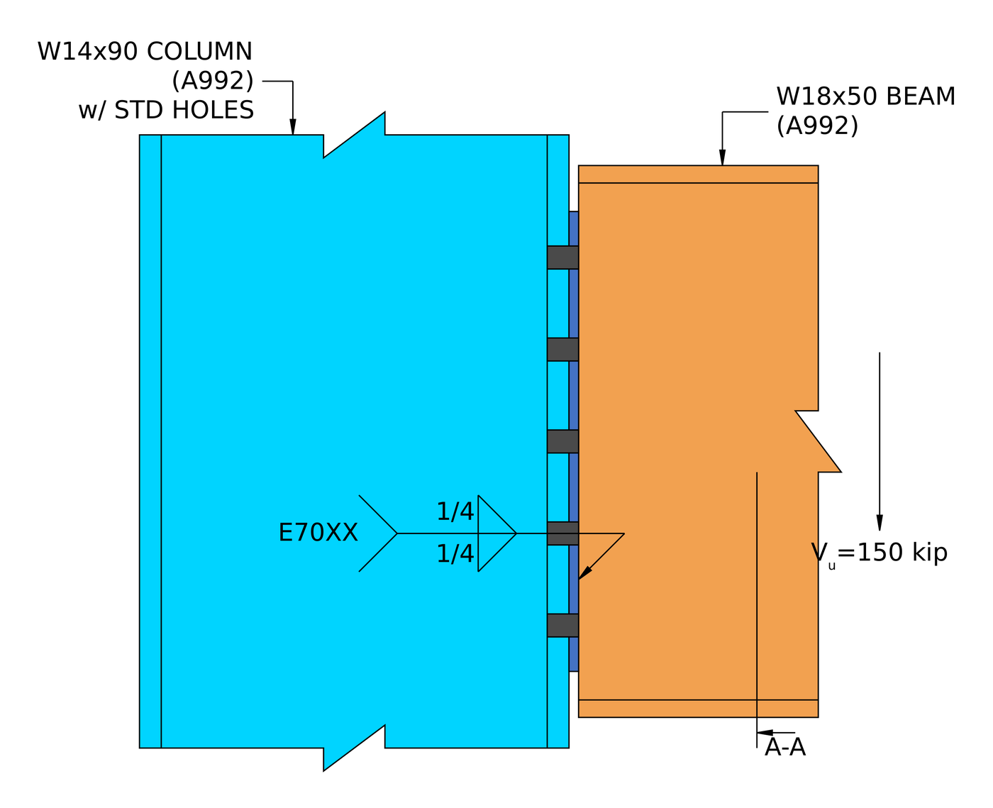
So a bigger weld does not always help. In the shear end plate example the 0.355 in beam web limits the usable weld to about 0.233 в, and the weld governs the connection at 0.995. For a single plate, the Manual also asks for fillets of [mathin] \frac{5}{8}\, t_{p} [mathin] с обеих сторон, so that the weld can develop the plate if it yields. Try sizes in the сварочный калькулятор.
9. The supporting and supported members
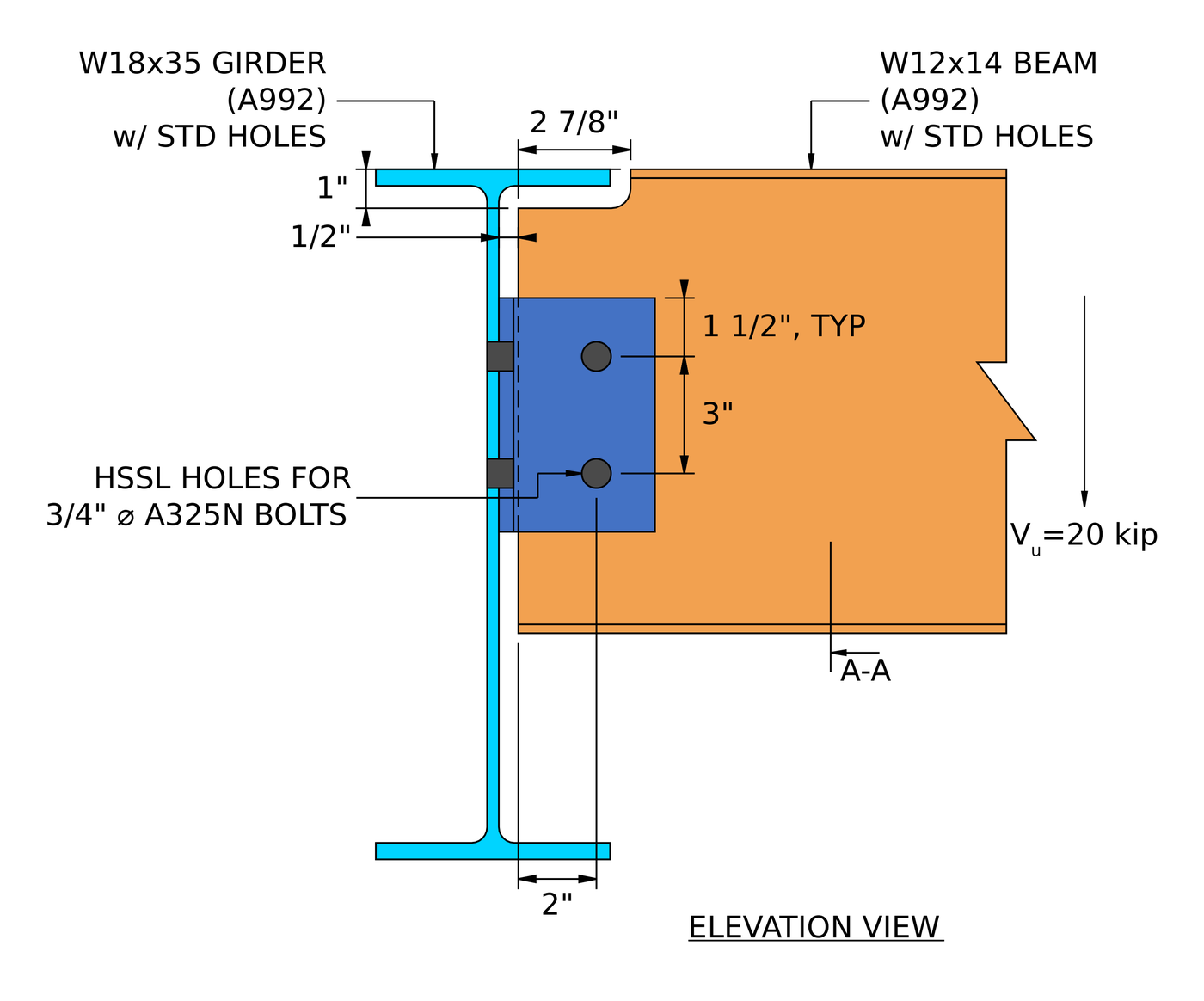
The connection is only as good as the steel it attaches to. A coped beam has a reduced section at the cope, which needs its own block shear, shear and flexure checks; the single angle example works these through for a W12x14 coped at the top flange. Where the beam frames into a girder web or a thin column web, check bearing and tear-out on that web too.
Shear connection design examples (Aisc 360-16 LRFD)
Each example below is a full AISC calc sheet from SkyCiv Connection Design, written out step by step with every equation, substituted value and DCR. They show how the governing check moves from one connection type to the next.
| пример | Members and load | Связь | Governing load check |
|---|---|---|---|
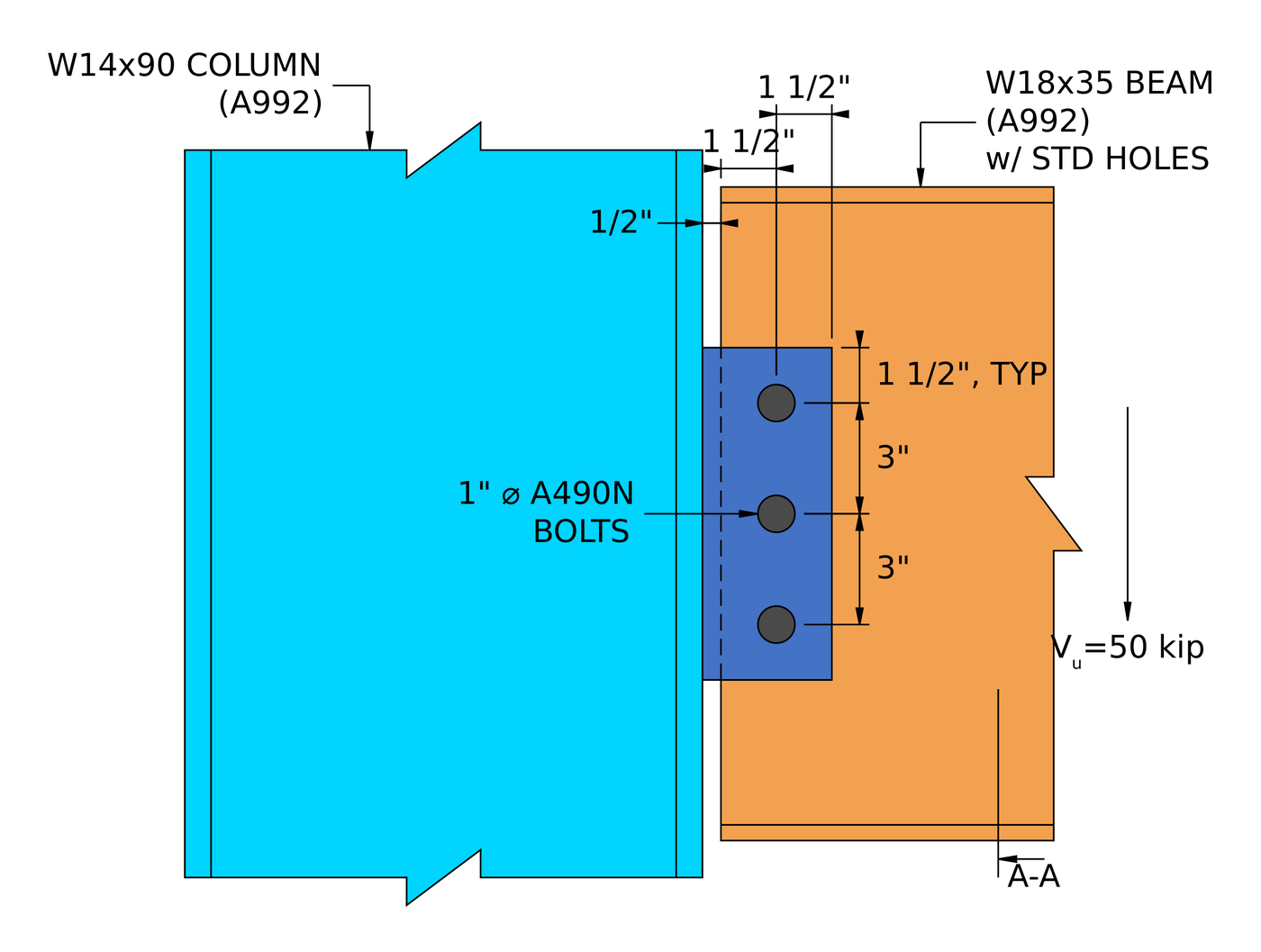
| Одиночная пластина (срезная вкладка) | W18x35 beam to W14x90 column flange, 50 кип | 1/2 в тарелке, три 1 в болтах А490-Н | Plate shear rupture, 0.629 |
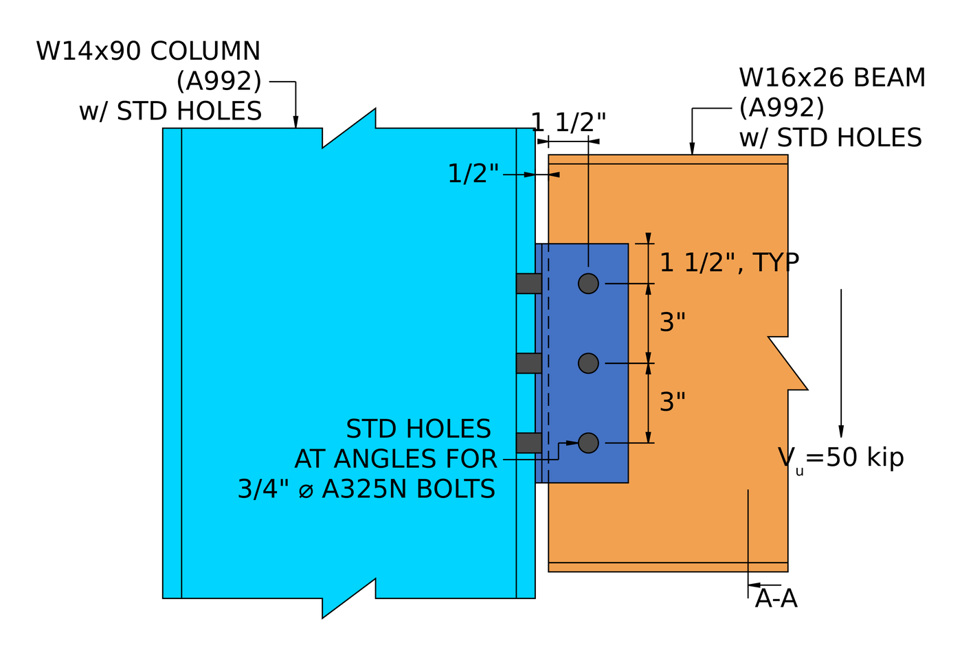
| Двойной угол | W16x26 beam to W14x90 column flange, 50 кип | 2Л4х3-1/2×1/4, three rows of 3/4 in A325-N each side | Болтовая опора на стенке балки, 0.760 |
| Один угол | Coped W12x14 beam to W18x35 girder web, 20 кип | L4x3x3/8, two rows of 3/4 in A325-N each leg | Bolt shear at the girder, 0.901 |
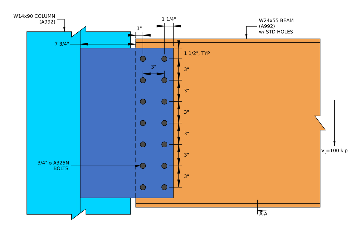
| Extended single plate | W24x55 beam to W14x90 column web, 100 кип | 3/8 Икс 13 Икс 21 в пластине А36, четырнадцать 3/4 в А325-Н | Взаимодействие сдвига и изгиба (разрыв), 0.938 |
| Shear end plate | W18x50 beam to W14x90 column flange, 150 кип | 5/16 Икс 8 1/2 Икс 15 в пластине А36, ten 3/4 в А325-Н, 1/4 in fillets | Weld at the beam web, 0.995 |
The pattern is worth knowing. A short, conventional shear tab is rarely close to its limit. Once the reaction moves away from the bolts, as in the single angle and the extended plate, the eccentricity drives the design. And in a welded connection like the end plate, the thinnest piece of base metal decides the weld.
For the theory behind all five, видеть design of steel connections using AISC 360-16.
Which shear connection should you use?
| Связь | Best for | Watch for |
|---|---|---|
| Одиночная пластина (срезная вкладка) | Most beam-to-column and beam-to-girder framing. One shop weld, one field bolt group | Пластичность пластины (TМаксимум), and the Table 10-9 limits on the conventional configuration |
| Extended single plate | Framing into a column web between the flanges, without coping the beam | Full eccentricity, plate flexure and the shear-flexure interaction |
| Двойной угол | Heavier reactions, and erection where the beam needs to be dropped in between supports | Bearing on a thin beam web, and two bolt groups to detail |
| Один угол | Light reactions, and access from one side only | Eccentricity at the support bolts, which cuts the group strength |
| Shear end plate | Shop-welded beams with fast, all-bolted field erection | Accurate beam length, and the weld limited by the beam web thickness |
Что проверяет программа?
Для сдвигового соединения, проектирование проходит как детализацию, так и проверку прочности.
Детализация выполняется первой и улавливает геометрию.: Расстояние до края болта, расстояние между болтами (шаг и калибр), зазоры между инструментами, и минимальные и максимальные размеры пластины, плюс обнаружение столкновений между пластинами, болты и сварные швы. Соединение, которое здесь терпит неудачу, никогда не достигает решения. Обычно это то, что вы хотите, потому что цифры не имеют значения, если деталь невозможно построить.
The strength checks then cover every limit state in the procedure above: bolt shear by ICOR, подшипник болта и вырыв, сдвиговый разрыв блока, текучесть при сдвиге и разрыв, plate flexure and its interaction with shear, пластичность, and weld strength with the base metal limit, plus the checks on coped beams and the supporting member. The calculation report shows every formula, проверка конструкции и полная ссылка на код, с номерами пунктов от AISC 360-16 или как 4100:2020, чтобы вы могли следить за расчетом, а не принимать его на веру. The worked examples above are written from those reports.
Со стороны крепления этого, см. документацию по болты и сварные швы.
В чем разница между соединением сдвига и момента?
Сдвиговое соединение передает только сдвиг.. Моментное соединение также передает изгиб.. Думайте об этом как о петля: сдвиговое соединение позволяет концу балки вращаться, момент связи удерживает его.
Различие заключается в выборе модели анализа., не только о деталях. Срезная пластина, спроектированная как простая, должна быть достаточно гибкой, чтобы ее можно было вращать., which is what the ductility check enforces, и моментное соединение должно быть достаточно жестким, чтобы оправдать устойчивость, предполагаемую моделью рамы..
| Срезное соединение | Момент соединения | |
|---|---|---|
| Переданные силы | Только сдвиг | Сдвиг и момент |
| Альтернативные названия | Закреплено, Петля, просто | Жесткий, Зафиксированный, Момент-сопротивляющийся |
| Aisc 360-16 срок | Простое подключение | Моментное соединение FR или PR |
| вращение | Позволяет вращение | Ограничивает вращение |
| Код исправления программного обеспечения | FFFFFR | FFFFFF |
Часто задаваемые вопросы
How do you calculate the capacity of a shear connection?
Work out the strength of every limit state along the load path (bolt shear with the eccentricity, bearing and tear-out on each ply, сдвиг блока, текучесть при сдвиге и разрыв, изгиб пластины, ductility and the welds) and take the lowest. That lowest value is the connection capacity, and the check that gives it is the governing limit state.
Is a shear connection the same as a pinned connection?
да, for analysis. A shear connection is modelled as a pin, free to rotate and carrying no moment. In practice it does carry a small moment, вот почему AISC 360-16 B3.4 asks that a simple connection have enough rotation capacity to accommodate the beam end rotation. The ductility limit on plate thickness is one way the design makes sure of that.
What is the eccentricity in a shear tab, and why is it a/2?
Таблица руководства AISC 10-9 задает расчетный эксцентриситет для обычного однопластинчатого соединения. For many bolt counts and hole types it is half the distance from the weld line to the bolt line, a/2, because the point of zero moment sits between the weld and the bolts. Outside the conventional limits, such as a plate extended into a column web, the full distance is used and the bolt group loses much more strength.
Which check usually governs a shear connection?
It depends on the type. In the five worked examples the governing load check was plate shear rupture (одиночная пластина), опираясь на стенку балки (двойной угол), bolt shear with eccentricity (одиночный угол), the shear-flexure interaction (extended single plate) and the weld (shear end plate). Thin beam webs and eccentricity are the two things to look at first.
Should the bolts be bearing type or slip-critical?
Most shear connections use snug-tight bearing-type bolts (A325-N, A490-N), which is what all five worked examples use. Slip-critical bolts are needed where slip would be a problem, such as oversized or slotted holes parallel to the load, or joints subject to fatigue or load reversal.
Can I design a shear connection with ASD instead of LRFD?
да. The limit states are identical. Replace [mathin] \phi R_{n} [mathin] с участием [mathin] R_{n} / \Omega [mathin] and compare against the ASD reaction. SkyCiv Connection Design runs both, and switching between them is one setting.
Do the examples follow the AISC 15th or 16th edition Manual?
They follow AISC 360-16 и Руководство AISC, 15-е издание., который написан вокруг этой спецификации. The 16th Edition Manual pairs with AISC 360-22. The shear connection limit states are much the same, but clause and table references move, поэтому проверьте их на соответствие версии, которую использует ваш проект..
Программное обеспечение SkyCiv Connection Design
Модели и проверки выше взяты из SkyCiv Connection Design. Он охватывает более 80+ предварительно настроенные типы подключения, проекты по стандарту AISC 360-16 (LRFD & ASD) и, как 4100:2020, и показывает каждую формулу, проверка конструкции и полная ссылка на код.
Вы можете смоделировать соединение в 3D., поменять болты, сварные швы или пластины без потери данных о нагрузке, создавать листы 2D-детальных чертежей в CloudCAD, и экспортируйте 3D-геометрию в IFC для координации в Revit., Текла или Navisworks.
Он работает полностью в браузере, без загрузок, обновления или настройка ИТ.
The full module adds the step-by-step calculation report, like the worked examples above, with every capacity and DCR.
Ссылки
- Aisc 360-16, Спецификация для зданий из конструкционной стали: Б3.4, Б4.3, Дж2.4 (уравнение. J2-4), J3.2 (Таблица J3.2), J3.3, J3.4 (Таблица J3.4), J3.5 (Таблица J3.5), J3.6 (уравнение. J3-1) и комментарии, J3.10 (уравнение. J3-6а, J3-6c), J4.2 (уравнение. J4-3, J4-4), J4.3 (уравнение. Дж4-5).
- Руководство по стальным конструкциям AISC, 15й выпуск: Часть 7 (уравнение. 7-1, мгновенный центр вращения); Часть 9 (base metal limit on weld size, coped beam flexure); Часть 10 (simple shear connections, Стол 10-9, уравнение. 10-3 и 10-4).
- КАК 4100:2020, Стальные конструкции.

Гарольд Муналем
Менеджер по продукту, Дизайн подключения
10+ лет в проектировании стальных соединений
LinkedIn

