
Extended single plate connection design to AISC 360 is the shear tab procedure for a plate that reaches well past the support, usually so the beam can frame into a column web and clear the column flanges. You check the bolt group for the full eccentricity, the plate thickness for ductility, bolt bearing and tear-out on the plate and the beam web, сдвиг блока, shear yielding and rupture, plate flexure and buckling, shear and flexure interaction, and the weld to the support. The long plate makes the bolt group eccentricity and the plate bending much larger than in a conventional shear tab, and that is what drives the design.
На этой странице от начала до конца работает один реальный пример.: a W24x55 beam framing into the web of a W14x90 column, с 100 kip LRFD reaction, through a 3/8 в х 13 в х 21 in A36 plate with fourteen 3/4 in A325-N bolts in two columns of seven. Дизайн соответствует AISC 360-16 и Руководство AISC, 15-е издание.. Каждое уравнение записано с его номерами, в том же порядке, что и расчетный лист AISC, в котором SkyCiv Connection Design модуль выдает для этого соединения.
What is an extended single plate connection?
An extended single plate connection is a shear tab that is longer than the conventional configuration allows. The plate is shop welded to the support and field bolted to the beam web, as with any single plate, but the bolts sit far enough from the weld that the AISC Manual’s simplified Table 10-9 approach no longer applies. It is still a simple connection under AISC 360-16 Б3.4, so it is detailed to rotate rather than resist moment.
The most common use is a beam framing into a column web. The beam end has to sit outside the column flanges, so the plate reaches out from the web to meet it. In this example the beam end is 7 3/4 in from the column web. A plate that long bends a lot more than a short tab, so the bolt group is designed for the full eccentricity and the plate is checked for buckling as well as yielding. It is one type of сдвиговое соединение, alongside the double angle connection, в single angle connection and the shear end plate connection. Вы можете проверить этот пример непосредственно в single plate connection calculator, which covers both the conventional and extended configurations.
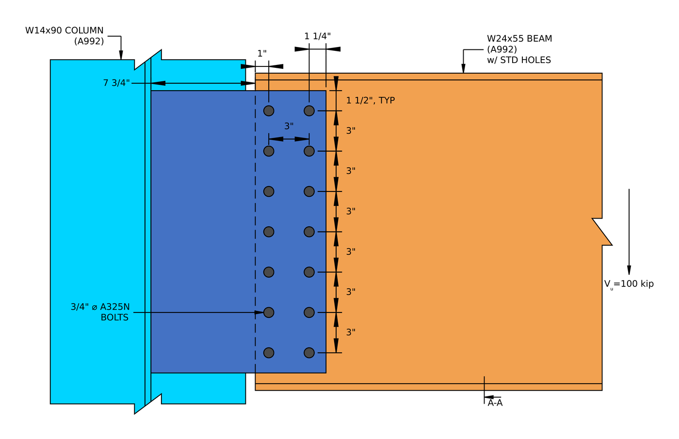
Высота примера соединения. The beam end sits 7 3/4 in from the column web, outside the column flanges, and the first bolt column is 1 in in from the beam end.
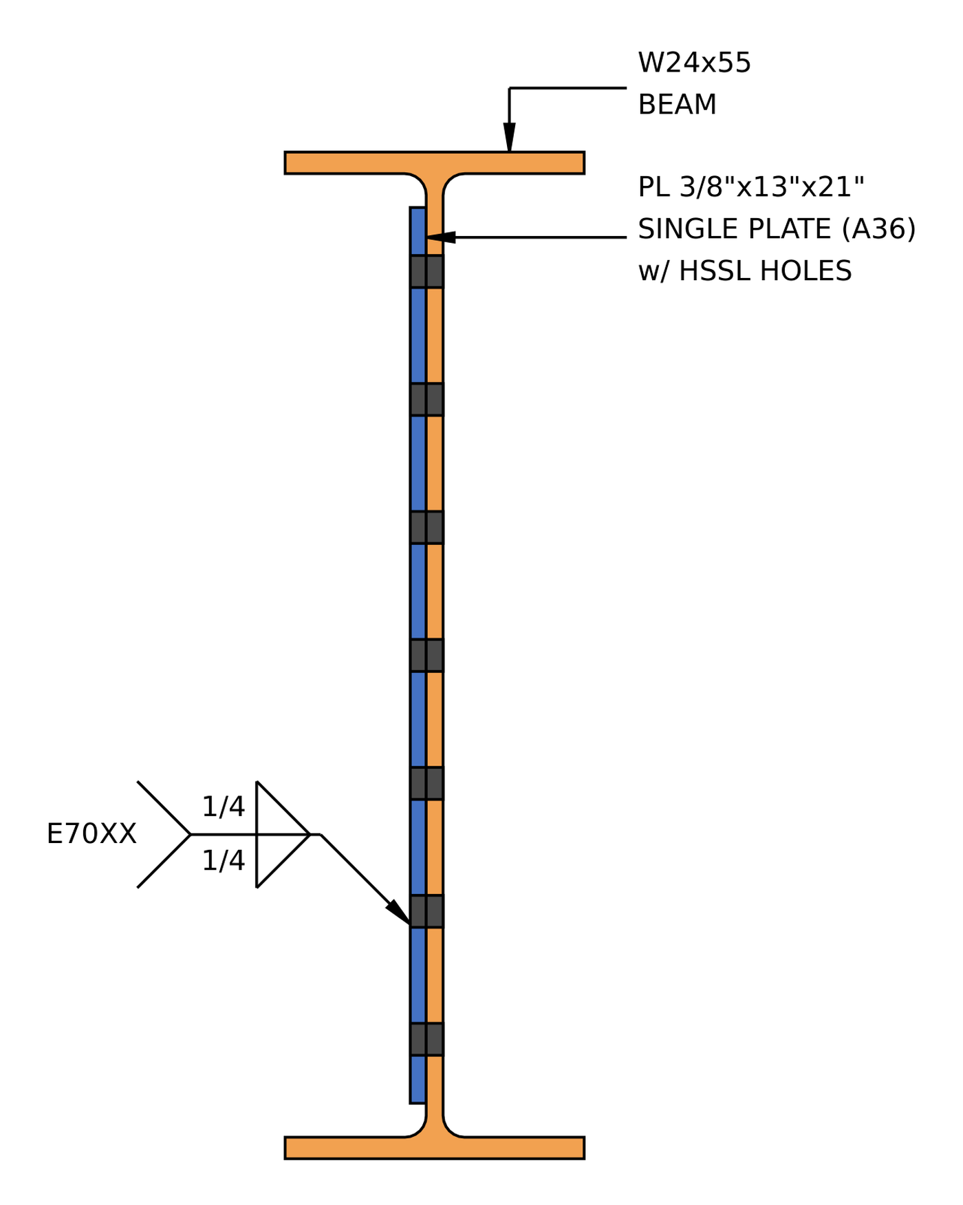
Section A-A. The plate has horizontal short-slotted holes and a 1/4 in fillet weld on both sides to the column web.
How do you design an extended single plate connection? The steps at a glance
- Check the detailing limits at the beam: расстояние между болтами, краевые расстояния, plate depth.
- Find the bolt group shear strength by the instantaneous center of rotation, for the full eccentricity.
- Check plate ductility: the plate must not be stronger in bending than the bolt group.
- Check bolt bearing and tear-out on the plate.
- Check bolt bearing and tear-out on the beam web.
- Combine shear, bearing and tear-out per bolt for the effective group strength.
- Check block shear of the plate.
- Check shear yielding and shear rupture of the plate.
- Check plate flexure and buckling using the double coped beam procedure.
- Check shear and flexure interaction for yielding.
- Check shear and flexure interaction for rupture.
- Check the detailing limit at the support.
- Check the weld size needed to develop the plate.
- Check the weld strength to the column web.
Проектирование входных данных для этого примера
Код дизайна: AISC. 360-16 LRFD. Свойства раздела взяты из руководства AISC..
| Вещь | Символ | Стоимость |
|---|---|---|
| Factored vertical shear | [mathin] V_{u} [mathin] | 100 кип |
| Луч | W24x55, A992 | |
| Beam depth | [mathin] d_{bm} [mathin] | 23.6 в |
| Beam web thickness | [mathin] t_{wb} [mathin] | 0.395 в |
| Beam flange width / толщина | [mathin] b_{fb},\ t_{fb} [mathin] | 7.01 в / 0.505 в |
| Beam area | [mathin] A_{bm} [mathin] | 16.2 дюйм² |
| Beam yield / растягивающее напряжение | [mathin] F_{yb},\ F_{ub} [mathin] | 50 KSI / 65 KSI |
| Столбец | в., A992 | |
| Глубина колонны / толщина полотна | [mathin] d_{sup},\ t_{ws} [mathin] | 14 в / 0.44 в |
| Ширина полки колонны / толщина | [mathin] b_{fs},\ t_{fs} [mathin] | 14.5 в / 0.71 в |
| Область столбца | [mathin] A_{sup} [mathin] | 26.5 дюйм² |
| Выход колонки / растягивающее напряжение | [mathin] F_{ys},\ F_{us} [mathin] | 50 KSI / 65 KSI |
| Модуль упругости | [mathin] E [mathin] | 29000 KSI |
| Вещь | Символ | Стоимость |
|---|---|---|
| Пластина (одиночная пластина) | PL 3/8 Икс 13 Икс 21, A36 | |
| Plate width / глубина / толщина | [mathin] b_{p},\ d_{p},\ t_{p} [mathin] | 13 в / 21 в / 0.375 в |
| Plate yield / растягивающее напряжение | [mathin] F_{yp},\ F_{up} [mathin] | 36 KSI / 58 KSI |
| Болты | 3/4 in A325-N, single shear | |
| Диаметр болта | [mathin] d_{b} [mathin] | 0.75 в |
| Bolt nominal tensile / напряжение сдвига | [mathin] F_{nt},\ F_{nv} [mathin] | 90 KSI / 54 KSI |
| Shear planes | [mathin] N_{s} [mathin] | 1 |
| Holes in plate / луч | Short-slotted horizontal (HSSL) / стандарт (ЗППП) | |
| сварка | 1/4 в филе, both sides, Е70ХХ | |
| Размер сварного шва / прочность наполнителя | [mathin] W,\ F_{EXX} [mathin] | 0.25 в / 70 KSI |
| Геометрия | Символ | Стоимость |
|---|---|---|
| Ряды болтов / междурядье | [mathin] n_{r},\ s_{r} [mathin] | 7 / 3 в |
| Болтовые колонны / column spacing | [mathin] n_{c},\ s_{c} [mathin] | 2 / 3 в |
| Beam web clearance (column web to beam end) | [mathin] clr [mathin] | 7.75 в |
| Horizontal edge distance on beam web | [mathin] L_{eh,bm} [mathin] | 1 в |
| Horizontal edge distance on plate | [mathin] L_{eh,pl} [mathin] | 1.25 в |
| Vertical edge distance on plate | [mathin] L_{ev,pl} [mathin] | 1.5 в |
| Bolt group eccentricity | [mathin] e [mathin] | 10.25 в |
The plate width adds up from the drawing: 7.75 in to the beam end, 1 in to the first bolt column, 3 in between columns and 1.25 in to the plate edge, 13 in in total. The plate depth is the two 1.5 in edge distances plus six 3 в пространствах, 21 в.
шаг 1: Detailing limits at the beam side (Aisc 360-16 J3.3, J3.4, J3.5)
Before any strength check, the bolt layout has to be buildable and match the assumptions behind the strength equations. Болты, затянутые слишком близко, рвутся между отверстиями., края, которые расположены слишком близко, вырываются, and a plate that is too short or too deep changes how the connection rotates.
Для 3/4 в болте минимальное расстояние составляет [mathin] 2\tfrac{2}{3} d_{b} = 2\,in [mathin] (J3.3) а минимальное краевое расстояние равно 1 в (Таблица J3.4). The plate has horizontal short slots, and its horizontal edge distance is measured from the end of the slot, поэтому приращение таблицы J3.5 1/8 in raises its minimum to 1.125 в. The plate depth has to be at least half the beam’s T dimension, 20 3/4 in for a W24x55, so the connection is stiff enough to brace the beam end, and it must also fit within the beam web.
| Лимит детализации | Лимит (в) | Действительный (в) | DCR | результат |
|---|---|---|---|---|
| Минимальное расстояние между рядами болтов | 2.000 | 3.000 | 0.667 | ПРОХОДЯТ |
| Максимальное расстояние между рядами болтов | 6.000 | 3.000 | 0.500 | ПРОХОДЯТ |
| Minimum bolt column spacing | 2.000 | 3.000 | 0.667 | ПРОХОДЯТ |
| Maximum bolt column spacing | 6.000 | 3.000 | 0.500 | ПРОХОДЯТ |
| Plate minimum vertical edge distance | 1.000 | 1.500 | 0.667 | ПРОХОДЯТ |
| Plate minimum horizontal edge distance | 1.125 | 1.250 | 0.900 | ПРОХОДЯТ |
| Beam minimum horizontal edge distance | 1.000 | 1.000 | 1.000 | ПРОХОДЯТ |
| Minimum connection depth | 10.375 | 21.000 | 0.494 | ПРОХОДЯТ |
| Maximum connection depth | 21.375 | 21.000 | 0.982 | ПРОХОДЯТ |
Для минимального предела соотношение превышает фактическое значение., а для максимума это актуально сверх лимита. The governing row is the horizontal edge distance on the beam web, which sits exactly at the 1 in minimum:
[math] DCR = \frac{d}{c} = \frac{(1)}{(1)} = 1 [math]
Прочность на единицу размера сварного шва 1.000 ≤ 1.0, Прочность на единицу размера сварного шва
The plate depth is also close to its upper limit at 0.982. А 21 in plate with seven rows is about as deep as this beam can take.
шаг 2: Bolt group shear strength by the instantaneous center of rotation (Aisc 360-16 J3.6)
The beam reaction reaches the plate at the bolt group, a long way from the weld, so the bolts carry a large moment as well as the shear. The instantaneous center of rotation (ИКОР) method finds the point the bolt group rotates about and turns that into a coefficient C, which is how many bolts’ worth of shear strength the group actually delivers.
Design eccentricity
For a conventional single plate, AISC Manual Table 10-9 lets you design the bolts for a reduced eccentricity. That table does not cover the extended configuration, so the bolt group is designed for the full distance from the weld line to the centroid of the bolt group. Here that is the beam clearance, plus the edge distance to the first bolt column, plus half the column spacing:
[math] e = clr + L_{eh,bm} + \frac{s_{c}}{2} = 7.75\,in + 1\,in + \frac{3\,in}{2} = 10.25\,in [math]
Strength of one bolt
С [mathin] \phi = 0.75 [mathin], [mathin] F_{nv} = 54\,ksi [mathin], [mathin] d_{b} = 0.75\,in [mathin] и [mathin] N_{s} = 1 [mathin]:
[math] \phi r_{v} = \phi\, F_{nv}\, \frac{\pi}{4} \left( d_{b} \right)^{2} N_{s}\, h_{f} = 17.892\,kip [math]
Вот [mathin] h_{f} = 1 [mathin] потому что нет наполнителей (Aisc 360-16 J5.2(а )):
[math] h_{f} = 0.85 \lt 1 – (0.4) \times \left( (0\,in) – (0.25\,in) \right) \le 1 \;\Rightarrow\; h_{f} = 1 [math]
Locating the instantaneous center
Болт 1 is at the bottom-left corner of the group, with the coordinates below. The IC is found by iteration, using the load-deformation curve of AISC Manual Equation (7-1) на страницах 7-6 в 7-8. В bolt group calculation using ICOR walks through that iteration in full.
| Болт | Икс (в) | и (в) |
|---|---|---|
| 1 | 0.00 | 0.00 |
| 2 | 0.00 | 3.00 |
| 3 | 0.00 | 6.00 |
| 4 | 0.00 | 9.00 |
| 5 | 0.00 | 12.00 |
| 6 | 0.00 | 15.00 |
| 7 | 0.00 | 18.00 |
| 8 | 3.00 | 0.00 |
| 9 | 3.00 | 3.00 |
| 10 | 3.00 | 6.00 |
| 11 | 3.00 | 9.00 |
| 12 | 3.00 | 12.00 |
| 13 | 3.00 | 15.00 |
| 14 | 3.00 | 18.00 |
The iteration converges with the IC at:
[math] x_{ic} = -1.3636\,in, \qquad y_{ic} = 9\,in [math]
The IC sits level with the middle row and just outside the left bolt column. The bolt reactions at that location are:
| Болт | р (кип ) | Rx (кип ) | Ry (кип ) | Mn (курица) |
|---|---|---|---|---|
| 1 | 17.44 | 17.24 | 2.61 | 158.76 |
| 2 | 16.64 | 16.23 | 3.69 | 102.40 |
| 3 | 14.40 | 13.11 | 5.96 | 47.45 |
| 4 | 10.37 | 0.00 | 10.37 | 14.15 |
| 5 | 14.40 | -13.11 | 5.96 | 47.45 |
| 6 | 16.64 | -16.23 | 3.69 | 102.40 |
| 7 | 17.44 | -17.24 | 2.61 | 158.76 |
| 8 | 17.56 | 15.80 | 7.66 | 175.65 |
| 9 | 17.09 | 13.82 | 10.05 | 126.77 |
| 10 | 16.20 | 9.18 | 13.35 | 85.78 |
| 11 | 15.53 | 0.00 | 15.53 | 67.77 |
| 12 | 16.20 | -9.18 | 13.35 | 85.78 |
| 13 | 17.09 | -13.82 | 10.05 | 126.77 |
| 14 | 17.56 | -15.80 | 7.66 | 175.65 |
That gives the two coefficients used in the rest of the design:
[math] C = 6.29 \qquad C’ = 72.195\,in [math]
Fourteen bolts deliver only 6.29 болты’ worth of vertical shear at a 10.25 в эксцентричности, so more than half the group’s concentric strength goes into resisting the moment. С’ is the coefficient for moment alone, which the ductility check in Step 3 использует.
Bolt group strength
[math] \phi R_{n} = \phi\, F_{nv}\, \frac{\pi}{4} \left( d_{b} \right)^{2} N_{s}\, C\, h_{f} [math]
[math] \phi R_{n} = (0.75) \times (54\,ksi) \times \frac{\pi}{4} \times \left( (0.75\,in) \right)^{2} \times (1) \times (6.29) \times (1) [math]
[math] \phi R_{n} = 112.54\,kip [math]
Прочность на единицу размера сварного шва 100 кип / 112.54 кип = 0.889 < 1.0, Прочность на единицу размера сварного шва
шаг 3: Plate ductility, maximum plate thickness (Ручное уравнение AISC. 10-3, 10-4)
A shear tab has to rotate as the beam deflects. If the plate is stronger in bending than the bolt group is in shear, the bolts fracture before the plate yields, which is a sudden, brittle failure. Capping the plate thickness makes sure the plate yields first. In the extended configuration this check is always required.
Первый, the moment strength of the bolt group, с использованием [mathin] C’ = 72.195\,in [mathin] from Step 2 и [mathin] F_{nv} = 54\,ksi [mathin]:
[math] M_{max} = \frac{F_{nv}}{0.9}\, \frac{\pi}{4}\, d_{b}^{2}\, C’ [math]
[math] M_{max} = \frac{(54\,ksi)}{0.9} \times \frac{\pi}{4} \times (0.75\,in)^{2} \times (72.195\,in) = 159.47\,kip\text{-}ft [math]
Then the thickest plate whose plastic moment does not exceed it, с участием [mathin] F_{yp} = 36\,ksi [mathin] и [mathin] d_{p} = 21\,in [mathin]:
[math] t_{max} = \frac{6\, M_{max}}{F_{yp}\, d_{p}^{2}} [math]
[math] t_{max} = \frac{6 \times (159.47\,kip\text{-}ft)}{(36\,ksi) \times (21\,in)^{2}} = 0.72323\,in [math]
Прочность на единицу размера сварного шва 0.375 в / 0.72323 в = 0.519 < 1.0, Прочность на единицу размера сварного шва
В 3/8 in plate is about half the limit. Fourteen bolts give the group a large moment strength, so there is plenty of room here.
шаг 4: Bolt bearing and tear-out on the single plate (Aisc 360-16 J3.10)
Each bolt pushes down on the edge of its hole in the plate. The plate either deforms at the hole (несущий, capped at 2.4 Поскольку расстояние до края меньше, чем соседнее расстояние до следующего отверстия под болт) or tears a strip out to the next hole or to the bottom edge (tear-out, 1.2 Поскольку расстояние до края меньше, чем соседнее расстояние до следующего отверстия под болт). The bottom bolt in each column has the shortest clear distance, so it is the weak one.
The slots run horizontally and the load is vertical, so the hole dimension across the member length is the standard [mathin] d_{h} = 0.8125\,in [mathin]. Clear distance for the edge bolt, с участием [mathin] L_{ev,pl} = 1.5\,in [mathin]:
[math] l_{c1} = L_{ev,pl} – \frac{d_{h}}{2} = (1.5\,in) – \frac{(0.8125\,in)}{2} = 1.0938\,in [math]
Свободное расстояние между болтами, с участием [mathin] s_{r} = 3\,in [mathin]:
[math] l_{c2} = s_{r} – d_{h} = (3\,in) – (0.8125\,in) = 2.1875\,in [math]
куда [mathin] t_{p} = 0.375\,in [mathin], [mathin] F_{up} = 58\,ksi [mathin], [mathin] C = 6.29 [mathin], [mathin] n_{r} = 7 [mathin] и [mathin] \phi = 0.75 [mathin]. The bracket is the strength of one line of seven bolts, and the factor C / n_r scales it for the eccentric group of two lines:
[math] \phi R_{n} = \phi \left[ \min\left(1.2\, l_{c1},\, 2.4\, d_{b}\right) t_{p} F_{up} + \min\left(1.2\, l_{c2},\, 2.4\, d_{b}\right) t_{p} F_{up} \left( n_{r} – 1 \right) \right] \left( \frac{C}{n_{r}} \right) [math]
[math] \phi R_{n} = (0.75) \times \left[ \min\left(1.2 \times (1.0938\,in),\, 2.4 \times (0.75\,in)\right) \times (0.375\,in) \times (58\,ksi) + \min\left(1.2 \times (2.1875\,in),\, 2.4 \times (0.75\,in)\right) \times (0.375\,in) \times (58\,ksi) \times \left( (7) – 1 \right) \right] \times \left( \frac{(6.29)}{(7)} \right) [math]
[math] \phi R_{n} = 177.54\,kip [math]
Прочность на единицу размера сварного шва 100 кип / 177.54 кип = 0.563 < 1.0, Прочность на единицу размера сварного шва
Tear-out governs the edge bolt, because 1.2 lc1 is less than 2.4 db. The inner bolts are capped by bearing.
шаг 5: Bolt bearing and tear-out on the beam web (Aisc 360-16 J3.10)
The same check applies to the beam web. The beam is not coped and its flanges are far from the bolts, so there is no edge to tear out to, and every bolt bears like an inner bolt.
[math] l_{c2} = s_{r} – d_{h} = (3\,in) – (0.8125\,in) = 2.1875\,in [math]
куда [mathin] t_{wb} = 0.395\,in [mathin], [mathin] F_{ub} = 65\,ksi [mathin] и [mathin] C = 6.29 [mathin]:
[math] \phi R_{n} = \phi\, \min\left(1.2\, l_{c2},\, 2.4\, d_{b}\right) t_{wb} F_{ub}\, C [math]
[math] \phi R_{n} = (0.75) \times \min\left(1.2 \times (2.1875\,in),\, 2.4 \times (0.75\,in)\right) \times (0.395\,in) \times (65\,ksi) \times (6.29) [math]
[math] \phi R_{n} = 218.02\,kip [math]
Прочность на единицу размера сварного шва 100 кип / 218.02 кип = 0.459 < 1.0, Прочность на единицу размера сварного шва
В 0.395 in web is thicker than the plate and has a higher tensile strength, so it is the stronger ply in this connection.
шаг 6: Effective strength of the bolt group (Aisc 360-16 J3.6 Commentary)
Срез болта, bearing and tear-out are not really separate checks. Each bolt delivers the least of its shear strength and its bearing or tear-out strength in each ply it passes through, and the group strength is the sum of those per-bolt values, scaled for the eccentricity.
Strength of one bolt in single shear:
[math] \phi r_{v} = \phi\, F_{nv}\, \frac{\pi}{4} \left( d_{b} \right)^{2} N_{s}\, h_{f} = (0.75) \times (54\,ksi) \times \frac{\pi}{4} \times \left( (0.75\,in) \right)^{2} \times (1) \times (1) = 17.892\,kip [math]
Bearing and tear-out of one bolt on the plate, for the edge bolt and an inner bolt:
[math] \phi r_{n1e} = \phi\, \min\left(1.2\, l_{c1},\, 2.4\, d_{b}\right) t_{p} F_{up} = (0.75) \times \min\left(1.2 \times (1.0938\,in),\, 2.4 \times (0.75\,in)\right) \times (0.375\,in) \times (58\,ksi) = 21.41\,kip [math]
[math] \phi r_{n1i} = \phi\, \min\left(1.2\, l_{c2},\, 2.4\, d_{b}\right) t_{p} F_{up} = (0.75) \times \min\left(1.2 \times (2.1875\,in),\, 2.4 \times (0.75\,in)\right) \times (0.375\,in) \times (58\,ksi) = 29.363\,kip [math]
Bearing of one bolt on the beam web:
[math] \phi r_{n2} = \phi\, \min\left(1.2\, l_{c2},\, 2.4\, d_{b}\right) t_{wb} F_{ub} = (0.75) \times \min\left(1.2 \times (2.1875\,in),\, 2.4 \times (0.75\,in)\right) \times (0.395\,in) \times (65\,ksi) = 34.661\,kip [math]
Bolts are numbered from the top of each line, so bolt 7 is the edge bolt on the plate:
[math] \phi r_{eff,1} = \min\left( \phi r_{v},\, \phi r_{n1i},\, \phi r_{n2} \right) = \min\left( (17.892\,kip),\, (29.363\,kip),\, (34.661\,kip) \right) = 17.892\,kip [math]
[math] \phi r_{eff,2} = \min\left( \phi r_{v},\, \phi r_{n1e},\, \phi r_{n2} \right) = \min\left( (17.892\,kip),\, (21.41\,kip),\, (34.661\,kip) \right) = 17.892\,kip [math]
| Болт | Срез болта (кип ) | Несущий / tear-out, тарелка (кип ) | Несущий / tear-out, beam web (кип ) | Effective strength (кип ) |
|---|---|---|---|---|
| 1 | 17.89 | 29.36 | 34.66 | 17.89 |
| 2 | 17.89 | 29.36 | 34.66 | 17.89 |
| 3 | 17.89 | 29.36 | 34.66 | 17.89 |
| 4 | 17.89 | 29.36 | 34.66 | 17.89 |
| 5 | 17.89 | 29.36 | 34.66 | 17.89 |
| 6 | 17.89 | 29.36 | 34.66 | 17.89 |
| 7 | 17.89 | 21.41 | 34.66 | 17.89 |
Sum over one line, с участием [mathin] n_{1} = 6 [mathin] bolts at the inner value and [mathin] n_{2} = 1 [mathin] at the edge value:
[math] \sum \phi r_{eff} = n_{1}\, \phi r_{eff,1} + n_{2}\, \phi r_{eff,2} = (6) \times (17.892\,kip) + (1) \times (17.892\,kip) = 125.25\,kip [math]
[math] \phi R_{n,eff} = \left( \frac{C}{n_{r}} \right) \sum \phi r_{eff} = \left( \frac{(6.29)}{(7)} \right) \times (125.25\,kip) = 112.54\,kip [math]
Прочность на единицу размера сварного шва 100 кип / 112.54 кип = 0.889 < 1.0, Прочность на единицу размера сварного шва
Bolt shear governs every bolt, so the effective strength equals the bolt group shear strength from Step 2. You can run the same connection in the free connection design calculator and try a larger bolt or a third bolt column to see how C moves.
шаг 7: Block shear of the single plate (Aisc 360-16 J4.3)
A block of the plate can tear out around the bolt group: shear down the line of holes nearest the beam, plus tension across both bolt columns to the plate’s free edge. This is an L-shaped block.
Чистая площадь в напряжении. The tension plane runs horizontally, along the slots, so it uses the slot length [mathin] d_{h} = 1\,in [mathin], с участием [mathin] n_{c} = 2 [mathin], [mathin] s_{c} = 3\,in [mathin] и [mathin] L_{eh,pl} = 1.25\,in [mathin]. Каждое отверстие добавляет 1/16 за повреждение во время удара кулаком (Б4.3):
[math] A_{nt} = t_{p} \left[ (n_{c}-1)\, s_{c} + L_{eh,pl} – (n_{c} – 0.5)\left( d_{h} + 0.0625\,in \right) \right] [math]
[math] A_{nt} = (0.375\,in) \times \left[ ((2)-1) \times (3\,in) + (1.25\,in) – ((2) – 0.5) \times ((1\,in) + (0.0625\,in)) \right] = 0.9961\,in^{2} [math]
Общая и чистая площади при сдвиге. The shear plane runs vertically, across the slots, so the net area uses [mathin] d_{h} = 0.8125\,in [mathin]:
[math] A_{gv} = t_{p} \left[ L_{ev,pl} + (n_{r}-1)\, s_{r} \right] = (0.375\,in) \times \left[ (1.5\,in) + ((7)-1) \times (3\,in) \right] = 7.3125\,in^{2} [math]
[math] A_{nv} = t_{p} \left[ d_{p} – L_{ev,pl} – (n_{r} – 0.5)\left( d_{h} + 0.0625\,in \right) \right] [math]
[math] A_{nv} = (0.375\,in) \times \left[ (21\,in) – (1.5\,in) – ((7) – 0.5) \times ((0.8125\,in) + (0.0625\,in)) \right] = 5.1797\,in^{2} [math]
Блок прочности на сдвиг, с участием [mathin] F_{up} = 58\,ksi [mathin], [mathin] F_{yp} = 36\,ksi [mathin] и [mathin] \phi = 0.75 [mathin]. With two bolt columns the tension stress is not uniform, because the column nearest the free edge takes more of it, так [mathin] U_{bs} = 0.5 [mathin]:
[math] \phi R_{n} = \phi \left( 0.6\, F_{up} A_{nv} + U_{bs} F_{up} A_{nt} \le 0.6\, F_{yp} A_{gv} + U_{bs} F_{up} A_{nt} \right) [math]
[math] \phi R_{n} = (0.75) \times \left( 0.6 \times (58\,ksi) \times (5.1797\,in^{2}) + (0.5) \times (58\,ksi) \times (0.9961\,in^{2}) \le 0.6 \times (36\,ksi) \times (7.3125\,in^{2}) + (0.5) \times (58\,ksi) \times (0.9961\,in^{2}) \right) [math]
[math] \phi R_{n} = 140.13\,kip [math]
Прочность на единицу размера сварного шва 100 кип / 140.13 кип = 0.714 < 1.0, Прочность на единицу размера сварного шва
The shear yielding side of the equation governs. A36 has a low yield-to-tensile ratio, so the gross shear plane yields before the net shear plane ruptures.
шаг 8: Shear yielding and shear rupture of the single plate (Aisc 360-16 J4.2)
The full reaction passes through the plate as vertical shear. The gross section must not yield, and the net section through the bolt holes must not rupture.
Shear yielding (уравнение. J4-3)
[math] A_{gv} = d_{p}\, t_{p} = (21\,in) \times (0.375\,in) = 7.875\,in^{2} [math]
[math] \phi R_{n,sy} = \phi\, 0.6\, F_{yp} A_{gv} = (1) \times 0.6 \times (36\,ksi) \times (7.875\,in^{2}) = 170.1\,kip [math]
Shear rupture (уравнение. J4-4)
[math] A_{nv} = t_{p} \left[ d_{p} – n_{r}\left( d_{h} + 0.0625\,in \right) \right] = (0.375\,in) \times \left[ (21\,in) – (7) \times ((0.8125\,in) + (0.0625\,in)) \right] = 5.5781\,in^{2} [math]
[math] \phi R_{n,sr} = \phi\, 0.6\, F_{up} A_{nv} = (0.75) \times 0.6 \times (58\,ksi) \times (5.5781\,in^{2}) = 145.59\,kip [math]
[math] \phi R_{n} = \min\left( \phi R_{n,sy},\, \phi R_{n,sr} \right) = \min\left( (170.1\,kip),\, (145.59\,kip) \right) = 145.59\,kip [math]
Прочность на единицу размера сварного шва 100 кип / 145.59 кип = 0.687 < 1.0, Прочность на единицу размера сварного шва
The section is cut by the holes of one bolt column only, because the vertical section where shear is checked passes through a single line of holes.
шаг 9: Plate flexure using the double coped beam procedure (Aisc 360-16 F11.2)
This is the check that sets an extended plate apart. The reaction acts at the bolts, 8.75 in from the weld, so the plate is a long cantilever in bending. Глубина, thin plate over that length can buckle sideways before it yields. The AISC Manual handles this with the procedure for a beam coped at both flanges, treating the plate like a beam web with the flanges cut away. The unbraced length is the distance from the weld to the first bolt column, [mathin] L_{b} = clr + L_{eh,bm} = 7.75\,in + 1\,in = 8.75\,in [mathin].
Range check
куда [mathin] E = 29000\,ksi [mathin], [mathin] F_{yp} = 36\,ksi [mathin], [mathin] d_{p} = 21\,in [mathin] и [mathin] t_{p} = 0.375\,in [mathin]:
[math] \frac{L_{b} d}{t^{2}} = \frac{(8.75\,in) \times (21\,in)}{(0.375\,in)^{2}} = 1306.7 [math]
[math] \frac{0.08 E}{F_{y}} = \frac{0.08 \times (29000\,ksi)}{(36\,ksi)} = 64.444 \qquad \frac{1.9 E}{F_{y}} = \frac{1.9 \times (29000\,ksi)}{(36\,ksi)} = 1530.6 [math]
Так [mathin] \frac{0.08E}{F_{y}} \lt \frac{L_{b} d}{t^{2}} \le \frac{1.9E}{F_{y}} [mathin], Оценка емкости сваи. F11-2 applies. В 1306.7 the plate is close to the 1530.6 upper limit, beyond which Eq. F11-3 for elastic buckling would take over.
Section moduli of the plate
[math] Z = \frac{t_{p} \left( d_{p} \right)^{2}}{4} = \frac{(0.375\,in) \times ((21\,in))^{2}}{4} = 41.344\,in^{3} [math]
[math] S = \frac{t_{p} \left( d_{p} \right)^{2}}{6} = \frac{(0.375\,in) \times ((21\,in))^{2}}{6} = 27.563\,in^{3} [math]
Lateral-torsional buckling modification factor (Ручное уравнение AISC. 9-15)
With no cope on the plate, [mathin] d_{ct} = 0\,in [mathin]:
[math] C_{b} = \left[ 3 + \ln\left( \frac{L_{b}}{d_{p}} \right) \right] \left( 1 – \frac{d_{ct}}{d_{p}} \right) \ge 1.84 [math]
[math] C_{b} = \left[ 3 + \ln\left( \frac{(8.75\,in)}{(21\,in)} \right) \right] \times \left( 1 – \frac{(0\,in)}{(21\,in)} \right) \ge 1.84 [math]
[math] C_{b} = 2.1245 [math]
Flexural yielding and buckling strength
С [mathin] \phi = 0.9 [mathin]:
[math] \phi M_{n} = \phi \left[ C_{b} \left[ 1.52 – 0.274 \left( \frac{L_{b} d}{t^{2}} \right) \left( \frac{F_{yp}}{E} \right) \right] F_{yp} S \le F_{yp} Z \right] [math]
[math] \phi M_{n} = (0.9) \times \left[ (2.1245) \times \left[ 1.52 – 0.274 \times ((1306.7)) \times \left( \frac{(36\,ksi)}{(29000\,ksi)} \right) \right] \times (36\,ksi) \times (27.563\,in^{3}) \le (36\,ksi) \times (41.344\,in^{3}) \right] [math]
[math] \phi M_{n} = 111.63\,kip\text{-}ft [math]
The plastic moment cap governs: 111.63 kip-ft is [mathin] \phi F_{yp} Z [mathin]. With C_b above 2, the buckling expression comes out well above the cap, so even at L_b d / t² = 1306.7 the plate reaches its full plastic moment. The equivalent shear capacity at the bolts is:
[math] \phi V_{n,y} = \frac{\phi M_{n}}{L_{b}} = \frac{(111.63\,kip\text{-}ft)}{(8.75\,in)} = 153.09\,kip [math]
Flexural rupture (Часть руководства AISC 15 Стол 15-3, Часть 9 уравнение. 9-4)
The net plastic section modulus removes the holes of one bolt column, с участием [mathin] d_{h} = 0.8125\,in [mathin], [mathin] s_{r} = 3\,in [mathin] и [mathin] n_{r} = 7 [mathin]. With an odd number of rows the last term applies:
[math] Z_{net} = \frac{t_{p} \left( d_{p} \right)^{2}}{4} – t_{p} \left( d_{h} + 0.0625\,in \right) s_{r} \left\lfloor \frac{n_{r}^{2}}{4} \right\rfloor – \left[ n_{r}\ \text{odd} \right] \frac{t_{p} \left( d_{h} + 0.0625\,in \right)^{2}}{4} [math]
[math] Z_{net} = \frac{(0.375\,in) \times ((21\,in))^{2}}{4} – (0.375\,in) \times ((0.8125\,in) + (0.0625\,in)) \times (3\,in) \times \left\lfloor \frac{(7)^{2}}{4} \right\rfloor – \left[ (7)\ \text{odd} \right] \times \frac{(0.375\,in) \times ((0.8125\,in) + (0.0625\,in))^{2}}{4} = 29.459\,in^{3} [math]
[math] \phi M_{n} = \phi\, F_{up} Z_{net} = (0.75) \times (58\,ksi) \times (29.459\,in^{3}) = 106.79\,kip\text{-}ft [math]
[math] \phi V_{n,r} = \frac{\phi M_{n}}{L_{b}} = \frac{(106.79\,kip\text{-}ft)}{(8.75\,in)} = 146.46\,kip [math]
Governing flexural capacity
[math] \phi V_{n} = \min\left( \phi V_{n,y},\, \phi V_{n,r} \right) = \min\left( (153.09\,kip),\, (146.46\,kip) \right) = 146.46\,kip [math]
Прочность на единицу размера сварного шва 100 кип / 146.46 кип = 0.683 < 1.0, Прочность на единицу размера сварного шва
Flexural rupture through the holes governs, by a small margin over yielding and buckling.
шаг 10: Shear and flexure interaction of the single plate, уступчивость (Часть руководства AISC 10)
The plate carries shear and bending at the same section at the same time, so the two have to be checked together. The Manual uses a circular interaction. This one combines the flexural yielding strength from Step 9 with the shear yielding strength from Step 8.
[math] I_{nt} = \left( \frac{V_{u}}{\phi V_{n}} \right)^{2} + \left( \frac{V_{u}}{\phi R_{n,sy}} \right)^{2} [math]
[math] I_{nt} = \left( \frac{(100\,kip)}{(153.09\,kip)} \right)^{2} + \left( \frac{(100\,kip)}{(170.1\,kip)} \right)^{2} = 0.7723 [math]
Прочность на единицу размера сварного шва 0.7723 / 1.0 знак равно 0.772 < 1.0, Прочность на единицу размера сварного шва
шаг 11: Shear and flexure interaction of the single plate, rupture (Часть руководства AISC 10)
The same interaction, with the flexural rupture strength from Step 9 and the shear rupture strength from Step 8. Both act on the net section through the holes.
[math] I_{nt} = \left( \frac{V_{u}}{\phi V_{n}} \right)^{2} + \left( \frac{V_{u}}{\phi R_{n,sr}} \right)^{2} [math]
[math] I_{nt} = \left( \frac{(100\,kip)}{(146.46\,kip)} \right)^{2} + \left( \frac{(100\,kip)}{(145.59\,kip)} \right)^{2} = 0.938 [math]
Прочность на единицу размера сварного шва 0.938 / 1.0 знак равно 0.938 < 1.0, Прочность на единицу размера сварного шва
This is the highest strength ratio in the connection. Each of the two rupture checks on its own is under 0.69, but together they come close to the limit. That is typical of a long plate, where the moment at the bolt line is large compared with the shear.
шаг 12: Detailing limit at the support side
The fillet weld sits in the gap between the column web and the end of the beam, so the weld cannot be larger than that clearance. With the beam held 7.75 in off the column web, this check has a lot of room.
[math] DCR = \frac{d}{c} = \frac{(0.25)}{(7.75)} = 0.032258 [math]
Прочность на единицу размера сварного шва 0.032 < 1.0, Прочность на единицу размера сварного шва
шаг 13: Weld required to develop the single plate (Часть руководства AISC 10)
The ductility check in Step 3 makes the plate yield first. That only works if the weld does not fail before the plate does. Two fillet welds, each at least 5/8 of the plate thickness, develop the strength of the plate.
[math] W_{duc} = \frac{5}{8}\, t_{p} = \frac{5}{8} \times (0.375\,in) = 0.23438\,in [math]
Прочность на единицу размера сварного шва 0.23438 в / 0.25 в = 0.938 < 1.0, Прочность на единицу размера сварного шва
The nearest standard size above 0.234 в том 1/4 в, so this ratio is set by rounding up, not by the load.
шаг 14: Fillet weld capacity to the column web (Aisc 360-16 Дж2.4)
Последний, the welds have to carry the reaction itself. Their strength depends on size, length and load direction. The base metal on either side of the weld, here the plate and the column web, can also limit how much of the weld size counts.
Предел основного металла по размеру сварного шва (Ручное уравнение AISC. 9-2)
This is the largest weld size, in sixteenths of an inch, that the thinner connected part can support. The plate is welded on both sides, so half its thickness is available to each weld. С [mathin] t_{p} = 0.375\,in [mathin], [mathin] F_{up} = 58\,ksi [mathin], [mathin] t_{ws} = 0.44\,in [mathin] и [mathin] F_{us} = 65\,ksi [mathin]:
[math] D_{max} = \frac{\frac{t_{p}}{2} F_{up} \le t_{ws} F_{us}}{3.09\,kip/in \times \left( F_{EXX} / 70\,ksi \right)} [math]
[math] D_{max} = \frac{(0.1875\,in) \times (58\,ksi) \le (0.44\,in) \times (65\,ksi)}{(3.09\,kip/in) \times (1)} = 3.5194 [math]
So only 3.52/16 в, о 0.220 в, из 1/4 in weld can be counted. В 3/8 in A36 plate cannot develop a full 1/4 in weld on both faces, and the plate rather than the 0.44 in column web sets the limit.
Effective length
Two lines of weld, each reduced by 2W at the ends:
[math] L_{w} = 2 \left[ d_{p} – 2W \right] = 2 \times \left[ (21\,in) – 2 \times (0.25\,in) \right] = 41\,in [math]
Прочность сварного шва
The load runs parallel to the welds, так [mathin] \theta = 0 [mathin] и нет направленного увеличения. С [mathin] F_{EXX} = 70\,ksi [mathin] и [mathin] \phi = 0.75 [mathin]:
[math] \phi R_{n} = \phi\, 0.6\, F_{EXX} \frac{\sqrt{2}}{2} \left( W \le \frac{D_{max}}{16} \right) \left[ 1 + 0.5 \left( \sin\theta \right)^{1.5} \right] L_{w} [math]
[math] \phi R_{n} = (0.75) \times 0.6 \times (70\,ksi) \times \frac{\sqrt{2}}{2} \times \left( (0.25\,in) \le \frac{(3.5194)}{(16)} \right) \times \left[ 1 + 0.5 \times (\sin(0))^{1.5} \right] \times (41\,in) [math]
[math] \phi R_{n} = 200.88\,kip [math]
Прочность на единицу размера сварного шва 100 кип / 200.88 кип = 0.498 < 1.0, Прочность на единицу размера сварного шва
Summary of the extended single plate connection design checks
| Проверка дизайна | требовать | Вместимость | DCR | результат |
|---|---|---|---|---|
| Detailing limits at beam side | 1.000 в | 1.000 в | 1.000 | ПРОХОДЯТ |
| Bolt group shear | 100.000 кип | 112.543 кип | 0.889 | ПРОХОДЯТ |
| тягучесть (maximum plate thickness) | 0.375 в | 0.723 в | 0.519 | ПРОХОДЯТ |
| Bolt bearing and tear-out, одиночная пластина | 100.000 кип | 177.544 кип | 0.563 | ПРОХОДЯТ |
| Bolt bearing and tear-out, beam web | 100.000 кип | 218.019 кип | 0.459 | ПРОХОДЯТ |
| Effective strength of bolt group | 100.000 кип | 112.543 кип | 0.889 | ПРОХОДЯТ |
| Block shear of single plate | 100.000 кип | 140.128 кип | 0.714 | ПРОХОДЯТ |
| Shear yielding and rupture of single plate | 100.000 кип | 145.589 кип | 0.687 | ПРОХОДЯТ |
| Plate flexure (double coped procedure) | 100.000 кип | 146.456 кип | 0.683 | ПРОХОДЯТ |
| Shear and flexure interaction, уступчивость | 0.772 | 1.000 | 0.772 | ПРОХОДЯТ |
| Shear and flexure interaction, rupture | 0.938 | 1.000 | 0.938 | ПРОХОДЯТ |
| Detailing limits at support side | 0.250 в | 7.750 в | 0.032 | ПРОХОДЯТ |
| Weld to develop single plate | 0.234 в | 0.250 в | 0.938 | ПРОХОДЯТ |
| Weld to support web | 100.000 кип | 200.877 кип | 0.498 | ПРОХОДЯТ |
The connection passes every check. The highest ratio, 1.000, is a detailing limit: the bolts are exactly the minimum 1 in from the beam end, и 21 in plate is at 0.982 of its maximum depth. Of the checks that compare load with capacity, shear and flexure interaction for rupture governs at 0.938, followed by bolt group shear at 0.889. Both come from the 10.25 в эксцентричности, which cuts the 14 bolts to 6.29 effective bolts and puts a large moment into the plate at the bolt line. The weld-to-develop ratio of 0.938 is a sizing rule, not a load check.
Что изменить, если проверка не удалась
- Bolt group shear or effective strength: use a larger bolt or a stronger grade, such as A325-X (threads excluded) or A490. Adding a bolt row raises C, but here the plate is already near its maximum depth, so a third bolt column is the other option.
- Interaction or plate flexure: используй более толстую тарелку, as long as the ductility check in Step 3 still passes. Reducing the beam clearance shortens L_b and the eccentricity, which helps every plate and bolt check.
- тягучесть (t_max): use a thinner plate, or add bolts so the group’s moment strength rises. A thicker plate makes this check worse.
- Tear-out on the plate: increase the vertical edge distance below the bottom bolt row.
- Блок сдвиг, shear yielding or shear rupture of the plate: use a thicker or deeper plate. A longer horizontal edge distance also adds to the block shear tension area.
- сварка: the base metal limit caps the useful weld size at about 0.220 in for a 3/8 in A36 plate, so a bigger weld adds nothing. A thicker or higher-strength plate raises that cap.
- A different connection: if the plate cannot be made to work, а double angle connection or a shear end plate with the beam coped to fit between the column flanges avoids the long cantilever altogether.
Часто задаваемые вопросы
В чем разница между обычным и удлиненным однопластинчатым соединением?
The conventional configuration in AISC Manual Part 10 covers a single vertical row of 2 в 12 болты, with the bolt line no more than 3 1/2 in from the weld and limits on edge distance and plate thickness. Within those limits you can use Table 10-9, with its reduced bolt eccentricity and no plate buckling check. Anything outside them, such as this plate with two bolt columns 8.75 in and 11.75 in from the weld, is the extended configuration. The bolt group is then designed for the full eccentricity, the plate thickness must pass the ductility check, and the plate is checked for buckling.
Why is the bolt eccentricity 10.25 в?
In the extended configuration the bolt group is designed for the distance from the weld line to the centroid of the bolts. That is the 7.75 in beam clearance, plus the 1 in edge distance to the first bolt column, plus half of the 3 in spacing between the two columns, 10.25 in in total.
Why does a beam framing into a column web need an extended plate?
The column flanges are in the way. A W14x90 flange is 14.5 in wide, so it projects about 7 in from the web on each side, and the beam end has to sit outside that line. The plate is welded to the column web and reaches out past the flange tips to the beam, which is why this example has a 7.75 in clearance and a 13 in wide plate. The other option is to cope the beam flanges so the beam fits between the column flanges, which lets you use a shorter, conventional plate.
Why is the block shear uniformity factor 0.5?
With two bolt columns, the tension across the block is not shared evenly. The bolt column closer to the free edge of the plate takes more of it. Aisc 360-16 J4.3 and its Commentary use U_bs = 0.5 for non-uniform tension stress, and the AISC Manual applies that to single plates with more than one bolt column.
Why does only part of the 1/4 in weld count?
Manual Eq. 9-2 limits the weld size to what the base metal can carry. The plate is 3/8 Вы можете заметить, что основное отличие заключается в соединении полок балки с опорной колонной., A36, and welded on both faces, so each weld can only be backed by half of it. That gives 3.52 шестнадцатые, or about 0.220 в, of usable weld size. В 1/4 in weld is still needed to meet the 5/8 t_p rule in Step 13, but its strength is calculated on the smaller size.
Why does shear and flexure interaction govern?
In a conventional tab the moment at the bolt line is small, so interaction rarely matters. Here the bolts are 8.75 in from the weld, so the moment is large. The plate’s flexural rupture strength (146.46 kip as equivalent shear) and its shear rupture strength (145.59 кип ) are almost equal. Squaring and adding the two ratios gives 0.938, even though each one on its own is below 0.69.
Does this example follow the AISC 15th edition or the AISC 16th edition Manual?
It follows AISC 360-16 и Руководство AISC, 15-е издание., which is written around that Specification. The AISC 16th Edition Manual pairs with the later 360-22 Спецификация. The limit states for an extended single plate connection are the same in both, but clause and page references move, so check them against the edition your project uses.
Как это изменится для AISC ASD вместо LRFD??
Предельные состояния и номинальная прочность идентичны.. With AISC ASD you compare the service-level reaction against the nominal strength divided by a safety factor instead of multiplying by a resistance factor. Коэффициент сопротивления 0.75 становится фактором безопасности 2.00, shear yielding’s 1.00 становится 1.50, and flexure’s 0.90 становится 1.67. Сочетания нагрузок тоже меняются., поэтому спрос ниже.
Design an extended single plate connection for free
Каждое число на этой странице получено из одного решения. Pick the single plate configuration, войти в свой луч, колонка, тарелка, bolts and reaction, и просмотрите каждую из этих проверок в своем браузере. Нечего устанавливать.
Модуль SkyCiv Connection Design — это программное обеспечение для проектирования соединений, лежащее в основе этого примера.. Он дает вам полный отчет о расчетах с каждым уравнением и вашими числами в нем., как шаги выше, плюс каждая емкость и DCR, для AISC 360-16 (ЛРФД и АСД) и, как 4100:2020. В калькулятор болтов и сварочный калькулятор прикрыть затворную группу и приварить чеки самостоятельно.
Ссылки
- Aisc 360-16, Спецификация для зданий из конструкционной стали: Б3.4, Б4.3, F11.2 (уравнение. F11-2), Дж2.4 (уравнение. J2-4), J3.3, J3.4 (Таблица J3.4), J3.5 (Таблица J3.5), J3.6 (уравнение. J3-1) and Commentary, J3.10 (уравнение. J3-6а, J3-6c), J4.2 (уравнение. J4-3, J4-4), J4.3 (уравнение. Дж4-5), J5.2(а ).
- Руководство по стальным конструкциям AISC, 15й выпуск: Часть 7, страницы 7-6 в 7-8 (уравнение. 7-1); Часть 9, уравнение. 9-2, 9-4 и 9-15; Часть 10, Стол 10-9, страница 10-87 and page 10-89 (уравнение. 10-3, 10-4); Часть 15, Стол 15-3.
- Расчет группы болтов с использованием ICOR
- Проектирование стальных соединений с использованием AISC 360-16
- Болты и сварные швы в дизайне соединений SkyCiv

Гарольд Муналем
Менеджер по продукту, Дизайн подключения
10+ лет в проектировании стальных соединений
LinkedIn
