Программное обеспечение Steel Member Design для Еврокода 3 (В 1993-1-1:2005)
Among the many design standards SkyCiv offers is Eurocode 3 (В 1993-1-1:2005), Проектирование стальных конструкций. The module checks hot-rolled and welded steel members to the Ultimate Limit State, with a deflection check for the Serviceability Limit State. It runs in SkyCiv Structural 3D, where it reads the members, сечений, материалов, forces and load combinations of your model.
С помощью этого модуля вы можете:
- Design I-shapes, Т-образные формы, углы, channels and hollow sections (RHS, SHS and CHS)
- Classify the cross-section (Класс 1, 2, 3 или 4) for each load combination and limit state, with effective properties for Class 4 сечений
- Check the resistance of cross-sections to tension, сжатие, bending about both axes and shear, including the reduction of the yield strength for high shear
- Check the combined resistance of cross-sections (bending and axial force)
- Check the buckling resistance of members: изгибный, torsional and torsional-flexural buckling in compression, lateral-torsional buckling in bending, and combined bending and axial compression with the interaction factors of Annex A or Annex B
- Split each member into lateral-torsional buckling segments, with C1 calculated from the bending moment diagram or entered by you
- Optionally check torsion (basic stress check) for I-shapes and rectangular hollow sections
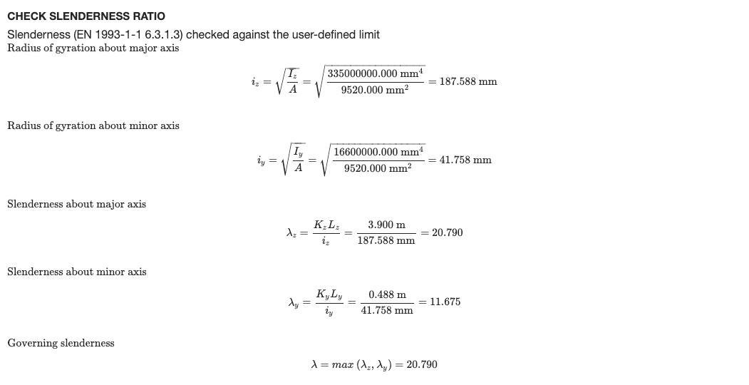
- Check the slenderness ratio (KL/r) against limits for compression and tension, optionally shown in the detailed report
- Check deflections against a span/deflection limit
- View the design ratios on the 3D model
- Export detailed step-by-step reports and a summary report, as HTML or PDF (Пользовательский логотип на Предприятие)
- Контролируйте параметры и ввод для каждого члена (Запустить дизайнер) чтобы найти наиболее эффективный раздел
- Полностью проверено со сторонними результатами
Поддержка текущей версии
Разделы
- I-Beam (I-shapes and H-shapes, hot-rolled or welded)
- Тавровая балка
- Угол
- канал
- Полый прямоугольный (RHS and SHS)
- Полый круговой (CHS)
The material must be steel. A Class 4 circular hollow section is outside the scope of the module and stops the check with an error message.
Единицы
The module only works in метрический единицы измерения. В модели, открыто настройки (верхняя панель) > Единицы и установите систему единиц измерения на метрический.
Design in SkyCiv Structural 3D
Этот модуль полностью интегрирован с нашим мощным программное обеспечение для расчета конструкций что позволяет инженерам моделировать, анализировать и проектировать с помощью одной модели. Модуль SkyCiv Design, the software pulls your entire model and checks each member against the criteria of the Standard to determine whether or not it passes the requirements of these European Standards. Нагрузки, members and design parameters are imported automatically, including the load combinations from EN 1990.
Щелкните здесь для получения более общей информации о нашей интегрированной Программное обеспечение для структурного проектирования
Открытие модуля
- Решите модель.
- Нажмите дизайн в верхней панели.
- В Выберите модуль проектирования, выбирать Стальной член.
- В Какой дизайн-код вы хотели бы начать?, выбирать Еврокод 3 (В 1993-1-1:2005), затем нажмите Начинать.
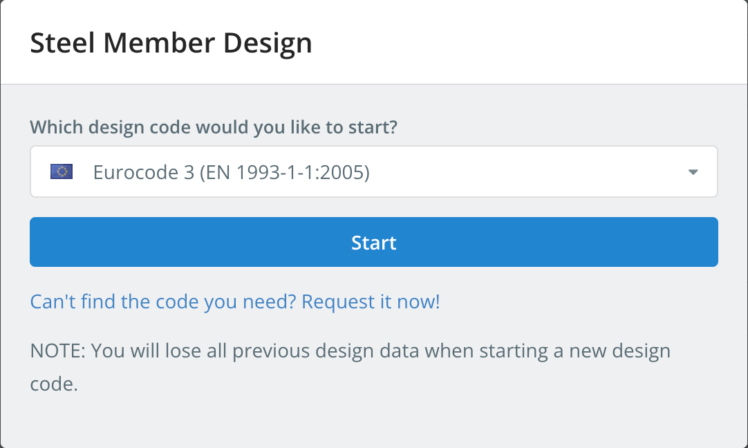
Starting a design code deletes the design data of the previous one. To switch codes later, использовать Начать новый код в дизайн меню.
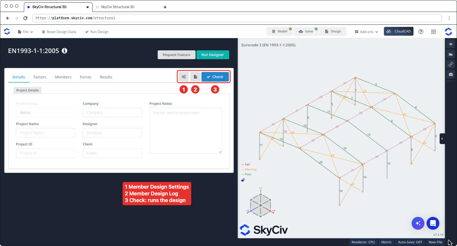
Панель дизайна открывается слева, с 3D-моделью справа. В заголовке указан код, плюс Запросить функцию и Запустить дизайнер. Справа от панели вкладок расположены три кнопки.: настройки (механизм) кнопка, который открывает Настройки дизайна элементов, кнопка журнала, который открывает Журнал проектирования элементов, и Проверьте, который запускает проверку проекта. Вкладки подробности, факторы, члены, сил и Полученные результаты.
Настройки дизайна элементов
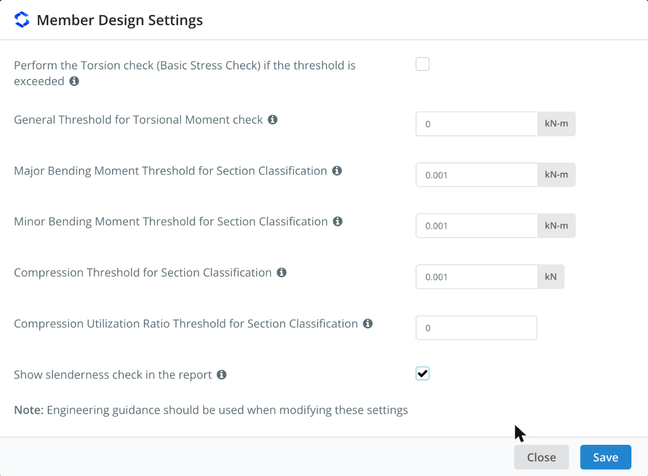
Нажмите кнопку шестеренки, чтобы открыть Настройки дизайна элементов. Наведите указатель мыши на значок ℹ рядом с настройкой, чтобы увидеть ее описание..
| Параметр | Выберите ось Z или Y | Описание |
|---|---|---|
| Perform the Torsion check (Базовая проверка стресса) if the threshold is exceeded | Не отмечен галочкой | Runs the torsion check of I-shapes and rectangular hollow sections when the torsional moment exceeds the threshold. Когда флажок снят, the torsion check is skipped whatever the threshold |
| General Threshold for Torsional Moment check | 0 кН-м | The torsional moment (in absolute value) above which the torsion check is performed, for all members whose Tпредел является авто в члены вкладка |
| Major Bending Moment Threshold for Section Classification | 0.001 кН-м | Bending about the major axis is included in the overall section classification of a limit state only when the moment exceeds this value |
| Minor Bending Moment Threshold for Section Classification | 0.001 кН-м | То же, for bending about the minor axis |
| Compression Threshold for Section Classification | 0.001 кН | Compression is included in the overall section classification of a limit state only when the compression force exceeds this value |
| Compression Utilization Ratio Threshold for Section Classification | 0 | Compression is included in the overall section classification only when its utilization ratio exceeds this value. It applies to all the limit states other than compression |
| Show slenderness check in the report | Не отмечен галочкой | Adds the slenderness check to the detailed report of each member, видеть Slenderness Ratio Check ниже |
The classification thresholds keep very small forces from governing the class of a section: Например, a beam with a negligible axial force is not classified as if it were in pure compression. Как отмечает диалог, при изменении этих настроек следует использовать инженерное руководство.. Нажмите Сохранять применять.
подробности
На подробности вкладка, вы можете ввести детали проекта (Компания, название проекта, Дизайнер, Идентификатор проекта, Клиент и Примечания к проекту). Вам не обязательно их заполнять, but anything you enter is shown in your reports. Единицы проекта шоу метрический и здесь нельзя изменить.
факторы
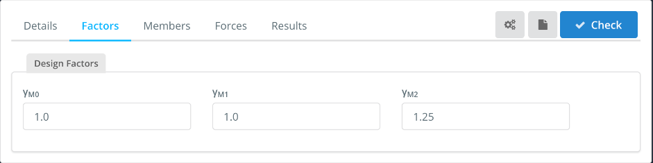
В факторы tab shows the partial factors for resistance, which you can change:
| Фактор | Used for | Выберите ось Z или Y |
|---|---|---|
| сМ0 | Resistance of cross-sections | 1.0 |
| сМ1 | Resistance of members to instability (потеря устойчивости) | 1.0 |
| сМ2 | Resistance of cross-sections in tension to fracture (net section) | 1.25 |
члены
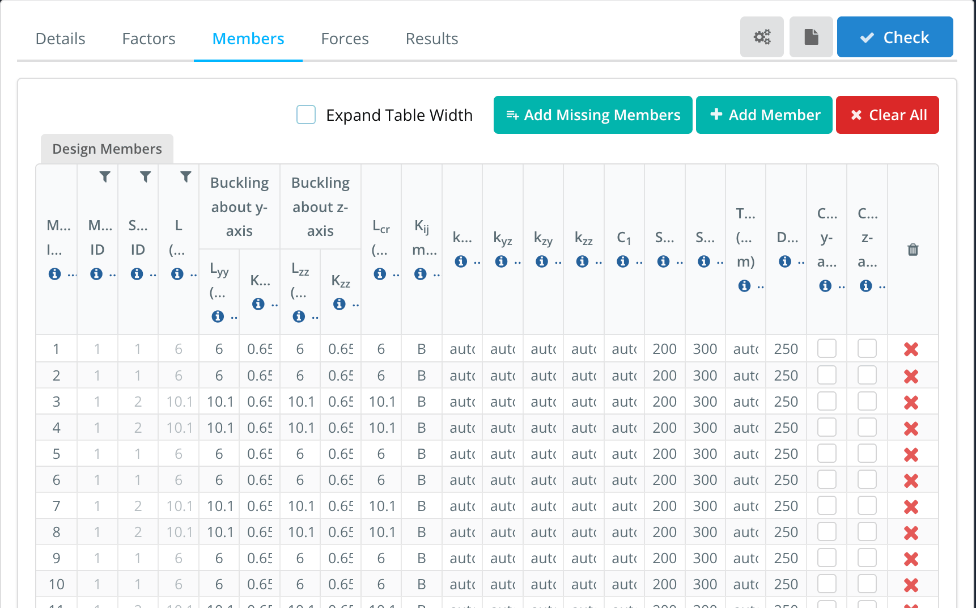
В члены на вкладке перечислены элементы дизайна, with one row for each member of the model. ID пользователя(s), Идентификатор материала, ID раздела и L come from the model. The buckling lengths and the other parameters are filled in with default values that you can change. Hover over the ℹ icon in a column header to see its description.
- Увеличить ширину стола: shows the full column headers and values, with a horizontal scroll bar.
- Add Missing Members, Эти цифры взяты из американского стандарта AISC. и Clear All: add the model members that are not in the table, add a design member, or remove all of them. Enter several member IDs, разделенных запятыми, в ID пользователя(s) to design them as a single design member.
| Столбец | Описание | Выберите ось Z или Y |
|---|---|---|
| Lгг, Кгг | Buckling length and effective length factor for flexural buckling about the y-y (major) ось, used to calculate Ncr | Lгг = member length, Кгг from the end fixity of the member |
| Lzz, Кzz | То же, about the z-z (minor) ось | Lzz = member length, Кzz from the end fixity of the member |
| Lcr | Buckling length for lateral-torsional buckling. Enter the member length, or comma-separated lengths, one for each segment between lateral restraints | Длина члена |
| Кij метод | Method used to calculate the interaction factors: А (Annex A, alternative method 1) или В (Приложение Б, alternative method 2) | В |
| Кгг, Кyz, КПлагин SkyCiv General Section Designer позволяет добавлять армирование и нагрузки для проверки моментов и осевых нагрузок вашей секции., Кzz | Interaction factors for bending and axial compression (уравнение. 6.61 и 6.62). С авто, they are calculated with the method chosen in Kij метод | авто |
| С1 | Moment modification factor for the elastic critical moment Mcr. С авто, it is calculated from the bending moment diagram of each segment. Enter a single value for all the segments, or comma-separated values, one for each segment | авто |
| SRС, SRT | Slenderness limits in compression and in tension, видеть Slenderness Ratio Check ниже | 200, 300 |
| Tпредел | Torsional moment threshold for the torsion check of this member. С авто, the general threshold of the settings is used. The torsion check must be ticked in the settings | авто |
| DefL | Коэффициент предела прогиба: the member passes when span/deflection is at least this value | 250 |
| Cantilever y-axis, Cantilever z-axis | Tick if the deflection check should consider the member as supported at one end only, for deflection along that axis | Не отмечен галочкой |
Например, для 10.1 m rafter with purlins every 2.02 м, входить 2.02,2.02,2.02,2.02,2.02 в Lcr. The lengths must add up to the member length (в пределах 1%). Each segment is then checked for lateral-torsional buckling with its own length and C1. If you enter a single length that is different from the member length, С1 can’t be calculated automatically and must be entered as a number.
сил
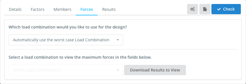
В сил tab sets the load combination used in the design. По умолчанию, Automatically use the worst case Load Combination checks every strength load combination of the model and reports the worst one for each check. You can also select a single load combination. Serviceability combinations are not listed here: they are used for the deflection check.
To view the forces of a load combination, select it in Select a load combination to view the maximum forces in the fields below, и нажмите Download Results to View.
Полученные результаты
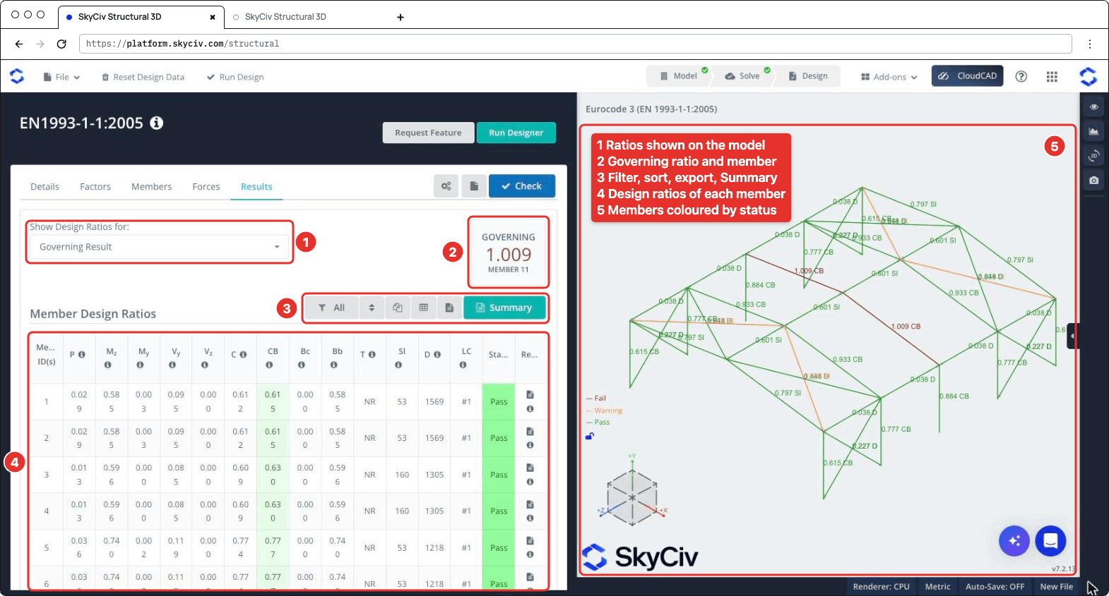
Нажмите Проверьте запустить проверку дизайна. В Полученные результаты вкладки показывают (numbered as in the screenshot below):
- Показать расчетные соотношения для: chooses which ratios are shown on the 3D model, Например Управляющий результат, Неудачные участники, a single check or the Worst Load Combination.
- УПРАВЛЯЮЩИЙ: наивысшее соотношение и его член.
- A toolbar to filter the members (Все, Failed, Прошло или Предупреждение элементов, or the members of a section), reset the sorting, copy the table, download it as CSV, download all the member reports as HTML, и откройте Резюме Пошаговый расчет и формула.
- В Коэффициенты проектирования элементов Таблица, с Положение дел (Проходить, Warn или Потерпеть поражение) and the report icon of each member. Наведите указатель мыши на значок ℹ в заголовке столбца, чтобы увидеть пункт, к которому он относится..
- The 3D view, where each member is coloured Потерпеть поражение, Предупреждение или Проходить and labelled with its governing ratio and check.
| Столбец | Проверьте | Пункт |
|---|---|---|
| п | Axial force, напряжение или сжатие | 6.2.3 или 6.2.4 |
| Mс участием | Bending about the major axis | 6.2.5 |
| Mи | Bending about the minor axis | 6.2.5 |
| Vи, Vс участием | ножницы | 6.2.6 |
| С | Комбинированные действия, resistance of cross-sections | 6.2.1 |
| ЦБ | Combined bending and axial compression, buckling resistance of members | 6.3.3 |
| Bc | Buckling resistance of compression members | 6.3.1 |
| Bb | Lateral-torsional buckling resistance | 6.3.2 |
| T | кручение (basic stress check), NR when it is not performed | 6.2.7 |
| Sl | Governing slenderness λ of the member (not a ratio) | |
| D | Span/deflection of the member (not a ratio) | |
| LC | Load combination of the governing result |
A member fails when one of its strength ratios is above 1.0. The slenderness and deflection checks are not part of the governing ratio: when the slenderness exceeds its limit, or the span/deflection is below DefL, в Sl или D value is highlighted and the member status is Warn. Their ratios to the limits are shown on the 3D model (Например 0.797 Sl) и в Резюме Пошаговый расчет и формула.
Отчеты
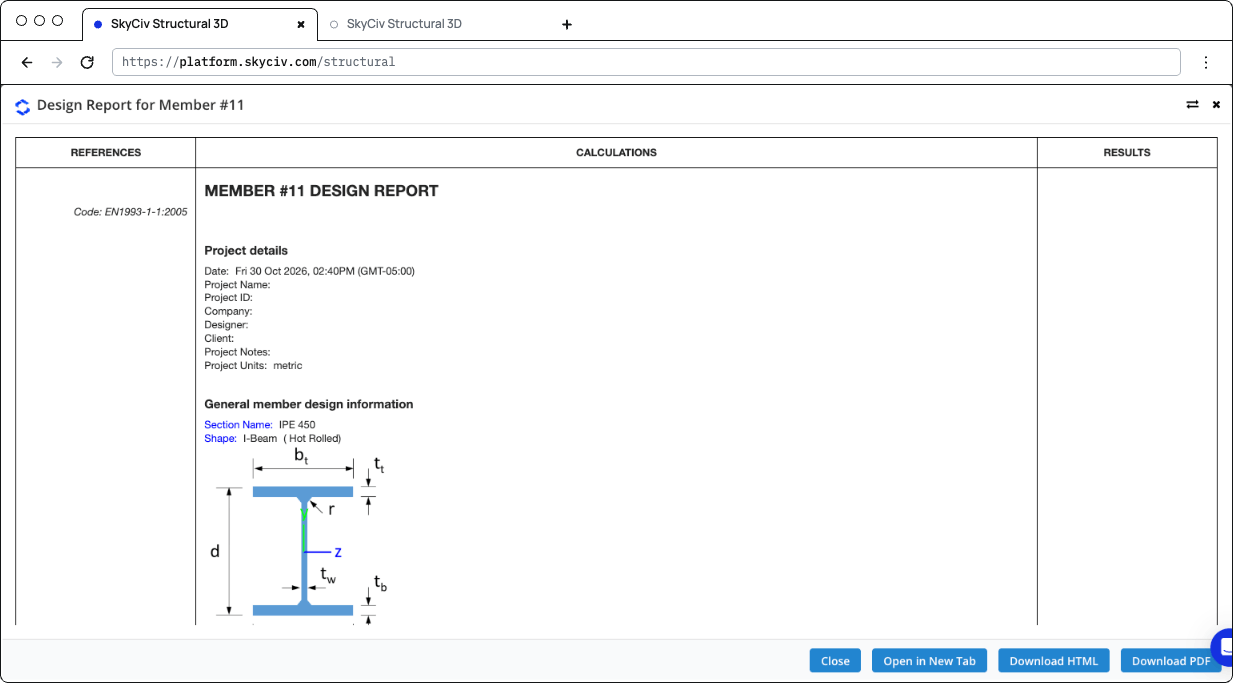
Click the report icon of a member to open its design report, в Отчет о проектировании для элемента № n диалог с Закрывать, Открыть в новой вкладке, Скачать HTML и Скачать PDF. The report shows the references (clauses), the calculations and the result (STATUS PASS или НЕУДАЧА) of each check:
- Детали проекта и General member design information: the section, its shape and fabrication (hot-rolled or welded), the material properties and the design parameters
- Design Internal Forces: the governing forces used for each check
- The checks of axial strength (напряжение или сжатие), axial buckling strength, flexural strength about the major and minor axes, lateral-torsional buckling resistance, interaction of combined resistance, interaction of combined buckling, shear strength along y and z and, when performed, кручение
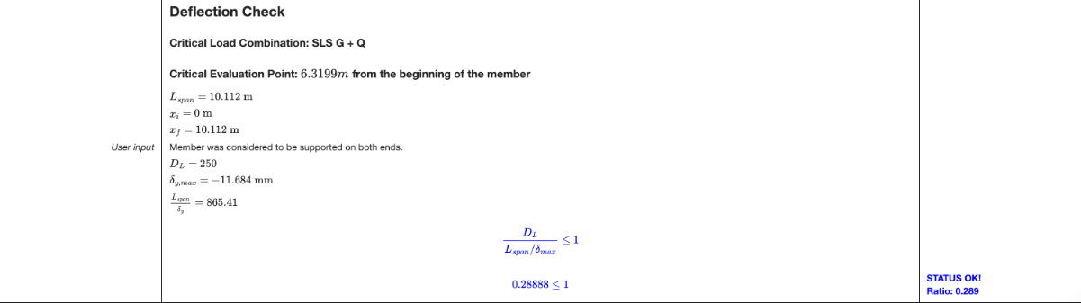
- Deflection Check: the critical serviceability load combination and position, the span, the maximum deflection and the ratio to the limit
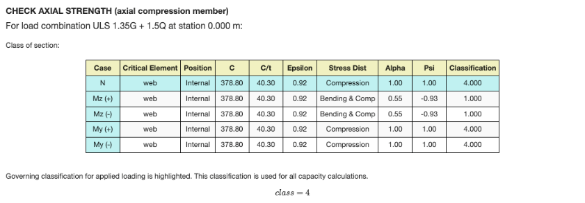
Each check gives the load combination and station that govern it, and the section classification table for that limit state: the class of each element (сеть, фланцы) for the axial force and for bending about each axis, with the governing class highlighted. Для класса 4 раздел, the effective properties are used. When the shear force is high (6.2.8), the reduced yield strength is used for the resistances.
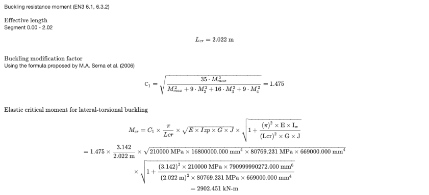
The lateral-torsional buckling check is calculated for the segment where the governing station is, with its Lcr и С1. When C1 является авто, it is calculated from the moments along the segment with the formula proposed by Serna et al. (2006). The report then gives Mcr, the non-dimensional slenderness, the buckling curve and the reduction factor χLT.
The deflection check is performed when the model has serviceability load combinations and DefL больше, чем 0. Otherwise the report says that the deflection check was skipped.
Нажмите Резюме on the Results tab to open the summary report. В нем перечислены детали проекта (код дизайна, user name and unit system), the design factors, материалы, the section dimensions and properties, the properties of each member (buckling lengths, Lcr, С1, См factors and limits), the results of all the members and the definitions of the symbols.
Проверок выполнено
Here are the details of some of the checks performed by the module.
Slenderness Ratio Check
Each member is checked against the slenderness limits entered in the члены вкладка: SRС for members in compression (200 по умолчанию) и SRT for members in tension or without axial force (300 по умолчанию). The slenderness is calculated about both axes from the effective length and the radius of gyration about the same axis:
- λс участием = Kс участиемLс участием / яс участием about the major axis, with iс участием = √(яс участием / А)
- λи = KиLи / яи about the minor axis, with iи = √(яи / А)
The governing slenderness λ = max(λс участием, λи) is divided by the limit, and the member passes when this ratio is 1.0 или менее. The slenderness check is listed in the Sl column of the Results tab.
To show this check in the detailed report of each member, open the settings (the gear button next to Проверьте) and tick Show slenderness check in the report. It’s off by default.
The report then has a Check Slenderness Ratio section after the buckling check, with the radii of gyration, the slenderness about each axis, the governing slenderness and its ratio to the compression and/or tension limit, with a PASS or FAIL status.