
В Разрезы пластин tool lets you extract forces, моменты, and other plate results across slabs, тарелки, или стены. It works in two modes: Резать, which reads results along a single line, и Полоска, which integrates results over a defined width. Это полезно для проектирования полосовых плит., проверка поведения местной пластины, и проверка распределения нагрузки.
Как использовать инструмент «Разрез сечения пластины»
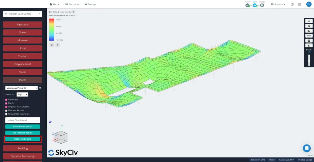
После решения, вы должны быть готовы к гораздо более крупным и сложным проектам Тарелки а потом Разрезы пластин на левой панели.
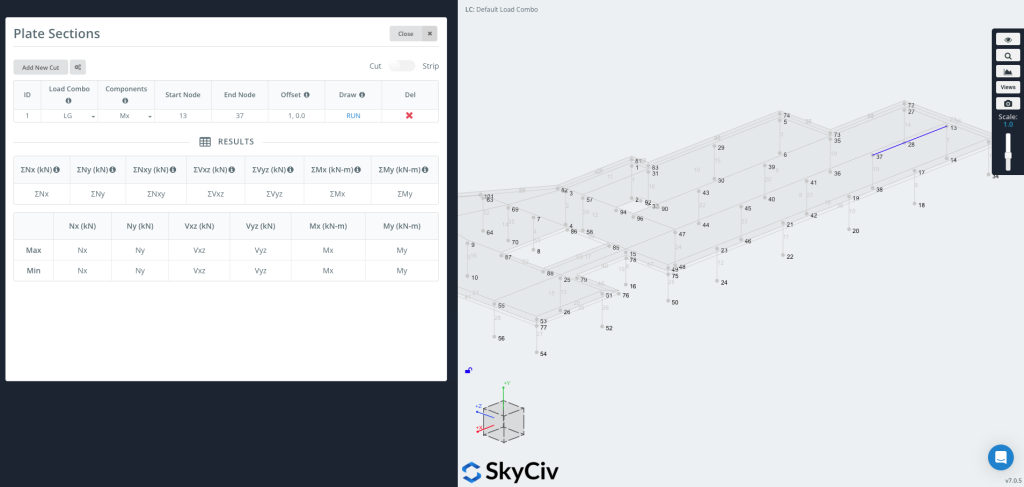
Нажмите «Добавить новую версию» чтобы создать новую запись.
Каждый разрез включает в себя:
- Загрузить комбо – Выберите, из какой комбинации нагрузок извлечь результаты..
- Компоненты – Выберите тип результата. The available components depend on the active mode (Cut or Strip) – see the sections below.
- Начальный узел / Конечный узел – Определите сегмент, в котором будет размещен разрез.. You can also enter coordinates directly, например.
[0,0,0]. - Компенсировать – Optionally shift the cut line. Enter it as
a,b, где а is the node ID that sets the offset direction and б is the offset distance (например.1, 0.5).- Это полезно, если вам нужен график с заданным смещением от края без вычисления координат вручную..
Использовать Резать / Полоска toggle in the top right corner to switch between the two modes. They differ in what they extract and which components are available.
Теперь вы можете рисовать & Запустите разрез
Нажмите БЕГАТЬ для создания разреза. Линия разреза появится на вашей модели. (как показано на правой стороне изображения), и таблица результатов будет заполнен максимальными и минимальными значениями для каждого выбранного компонента.
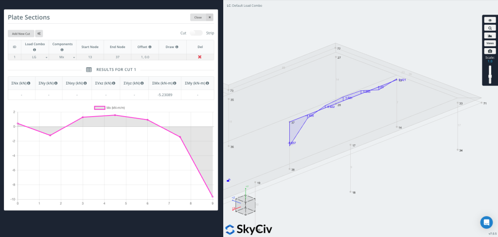
Теперь вы можете построить график непосредственно на геометрию, визуальное отображение результатов вдоль линии разреза.
Cut Mode – Results Along a Line
В Резать mode the tool reads plate results along the cut line and reports them per unit length, together with the summed (Σ) total along the whole cut.
- Компоненты – Nx, Ny, Nxy, Вхз, Vyz, Mx, Мой (или Все at once), the Wood-Armer design moments (М1 / М2, Вершина / Нижний), and Soil Pressure.
- Оси – Results are reported in each plate’s local axes.
- Единицы – Force or moment per unit length for the diagram; the results table shows the totals ΣNx … ΣMy along the cut.
Strip Mode – Results Over a Width
Turn on the Полоска toggle in the top right corner to generate a strip section.
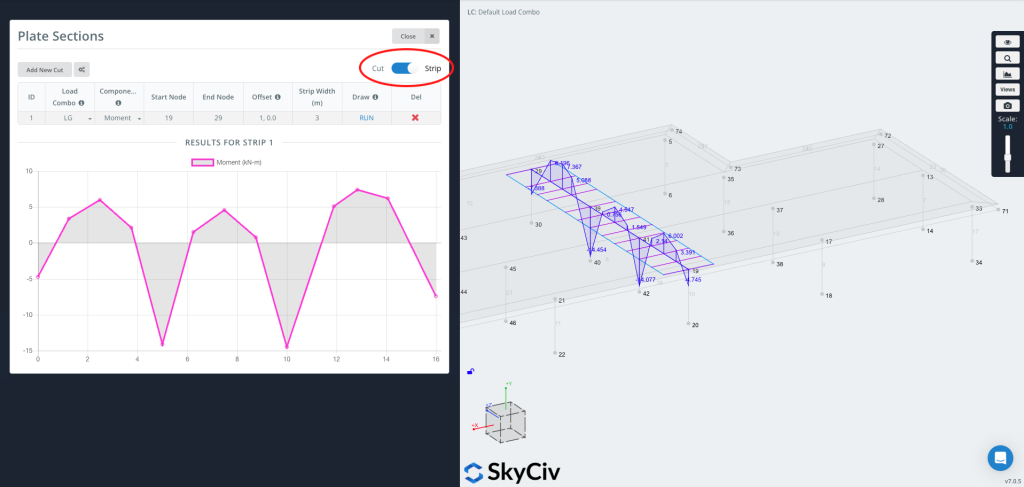
А Полоска извлекает результаты по ширине, not just along a line. At each station along the cut it integrates the plate results across the strip width, so the reported value is the total force or moment carried by that slice of slab. This is typically used for конструкция полосовой плиты, where design codes work with forces and moments over a strip of slab rather than at a single point.
Strip axis convention
A strip has a longitudinal axis running from the start node to the end node, and it is treated as an equivalent луч along that axis. All plate results are first transformed into this axis and then integrated across the strip width: the bending moment is reported about the strip axis, just as you would read the bending moment of a beam running along it, and the axial, shear and in-plane shear forces are resolved and summed the same way. Коротко, the distributed plate forces are reduced to the resultant forces and moments that an equivalent beam of that width would carry.
Полоса пригодится, когда вам нужно:
- Расчетные значения для односторонних и двусторонних полос плит
- Более репрезентативные значения на физической полосе, а не на одной линии
- Code-based averaging of peak values (see Peak Moment Ratio below)
Strip-specific inputs
- Strip Width – Enter
Wl,Wrfor an asymmetric strip, где Wl is the width to the left and Wr the width to the right (viewed from start to end). Enter a single value for a symmetric strip. - Компоненты – Moment, ножницы, аксиальный, In-plane Shear, и M comb top / M comb bot (combined reinforcement design moments – see below).
- Peak Moment Ratio (необязательный) – Enable this option in the settings to cap the peaks of the diagram and distribute the moment more evenly across the strip, as required by code-based averaging such as the CSA two-thirds rule. Enter a ratio between 0 и 1 (1.0 = no capping).
M comb top / M comb bot (combined design moments)
The “M comb” components are the combined Wood-Armer design moments. At every point a plate carries two bending moments and a twisting moment Mxy. Reinforcement bars resist bending along their own direction but not twist, so the twisting moment has to be folded into the bending moments – the Wood-Armer method does this, giving a single equivalent design moment for each reinforcement layer.
Вершина и низ refer to the two reinforcement layers (the two faces of the plate), and they are defined by the local z-axis of each finite element’s coordinate system: the face the local +z axis points toward is the верхняя, and the opposite face is the низ. Because the local axes are assigned per element – and depend on how each element is defined and the order of its nodes – check the element local axes in the model to confirm which physical face is top and which is bottom. M comb top sizes the reinforcement near the top face, и M comb bot the reinforcement near the bottom face.
Because the results are integrated across the width, Strip values are reported in force or moment units (not per unit length).
Cut vs Strip – Which to Use
- Использовать Резать for a quick diagram of a result component along a line (in plate axes), or to get the total (Σ) across the cut.
- Использовать Полоска when you need design forces and moments over a finite width (конструкция полосовой плиты), combined reinforcement moments (M comb), or code-based peak averaging.
