A guide on the Direct Strength Method for Cold Formed Steel
Cold-formed steel member design is challenging due to the complex stability behavior of the thin-walled members. To address this problem several methods have been developed, like the Direct Strength Method (DSM), the most flexible and modern approach. SkyCiv is committed to help supporting DSM, through resources such as this and software that supports cold formed steel design through this approach.
The DSM provides predictions of cold-formed member strength without calculating effective widths [1] (effective widths calculation is often a complex process with many limitations to analyze complex geometric shapes). En este método, the calculation of critical buckling strength can be carried out in various approaches, mainly the Finite Strip Method (FSM) and the Finite Element Method (CINCO). En esta guía, we will explore:
- What is the Direct Strength Method
- Acceptance and Adoption in the Industry
- Conventional Finite Strip Method
- Buckling Mode Types
- What are the DSM Factors?
- Finite Strip Method in SkyCiv Section Builder
What is the Direct Strength Method (DSM)
El Método de fuerza directa (DSM) is a design approach used predominately for the analysis and design of cold-formed steel members. Unlike traditional methods (such as the Effective Width Method) that rely on calculating effective section properties to account for local buckling, the DSM directly computes the member’s strength using its full, unreduced cross-sectional properties.
Pros and Cons of Direct Strength Method
| Pros | Contras |
|---|---|
| Simplifies Design Process: Reduces complexity by eliminating effective width calculations. | Learning Curve: Requires engineers to become familiar with new concepts and formulations. |
| Enhanced Accuracy: Directly accounts for various buckling modes for precise strength predictions. | Limited Historical Data: Less empirical data available for some specific applications compared to traditional methods. |
| Versatile Application: Suitable for complex and unconventional cross-sections. | Software Dependence: May require advanced software tools not readily available to all practitioners. |
| Unified Methodology: Provides a consistent approach across different buckling behaviors. | Standard Compliance: Not all regional codes may fully incorporate DSM provisions yet. |
| Facilitates Innovation: Encourages the use of new materials and shapes due to its adaptable framework. | Resistance to Change: Industry inertia can slow adoption as practitioners stick to familiar methods. |
Adoption and Acceptance:
The DSM is recognized and incorporated into major international design standards, como:
- AISI S100: Especificación norteamericana para el diseño de miembros estructurales de acero conformados en frío.
- AS / NZS 4600: Australian/New Zealand Standard for Cold-Formed Steel Structures.
DSM is also being prioritised as a future method by being taught in universities and becoming a more common method taught in cold formed design courses. We’re also seeing an increase in it’s support by structural analysis and design software packages who are integrating DSM into their design modules.
sin embargo, there are still some obstacles and challenges in the DSM being widely-adopted, since it is a relatively new/untaught method. Transitioning from traditional methods requires training and adaptation, which some practitioners can be reluctant to undertake.
Conventional Finite Strip Method
The FSM was created as a simplification of the FEM, both methods have the same theoretical background, and the FSM is also a matrix method. By defining the nodes and elements of a section it is possible to analyze any complex shape. This encourages section optimization and simplifies the analysis process.
Several options, including open-source tools, are currently available to perform Finite Strip analysis. sin embargo, integrating these tools with general analysis and design software has proved challenging due to their complex nature. SkyCiv has recently built a Finite Strip Method analysis tool which is fully integrated into our Constructor de Sección software. This tool automates calculation of DSM factors for standard and custom cold-formed sections, allowing for DSM steel design in accordance with AISI S100, AS 4600 and other international standards.
The FSM discretizes the section’s transversal shape into longitudinal strips [3]. This simplifies the traditional 3D analysis problem with 6 degrees of freedom to a problem with 4 grados de libertad. The strips are analyzed for different lengths called half-wavelength.
Usando las propiedades de la sección geométrica, el material, las tensiones, y la condición de carga, Se construyen dos matrices globales., la matriz de rigidez elástica (Ke) y la matriz de rigidez geométrica (kilos).
Finalmente, esto representa un problema de descomposición de valores propios, donde los valores propios representan los factores de carga, y los vectores propios contienen la forma deformada.
![]()
Buckling Mode Types
Las clases de pandeo se organizan en tres grupos principales., global, local, y distorsionante, dependiendo del tipo de falla.
pandeo local: Pandeo que implica una distorsión significativa de la sección transversal., pero esta distorsión incluye sólo la rotación, no traducción, en las líneas de pliegue internas [2].
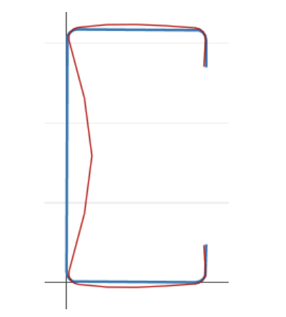
Pandeo distorsional: Pandeo que implica una distorsión significativa de la sección transversal., pero esta distorsión incluye rotación y traslación en una o más líneas de pliegue internas de un miembro [2].
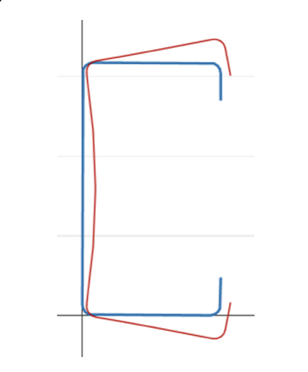
pandeo global: Pandeo que no implica deformación de la sección, en lugar de traducción (flexura) y/o rotación (torsión) de toda la sección transversal ocurre [2].
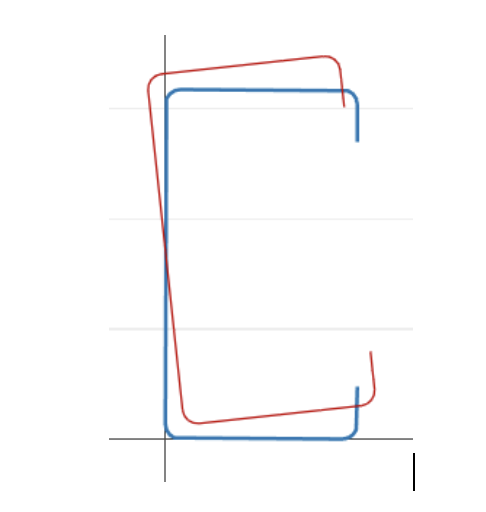
Por esta definición podemos inferir que existe una fuerte correlación geométrica entre la clasificación de pandeo y la forma deformada., mostramos el deformado para cada punto de la curva de firma.
DSM Factors
Finite Strip Method in SkyCiv Section Builder
SkyCiv has a Direct Strength Method Calculator built into our Section Analysis Software (SkyCiv Section Builder) which can automatically calculate the key DSM factors for any custom cold formed steel shape. Simply start from the Section Builder module by loading in a CFS section and clicking Design -> Acero Conformado en Frío (CF):
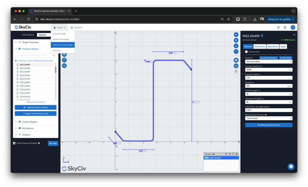
De aquí, the DSM factors will be automatically calculated, ready for the user to review and submit:
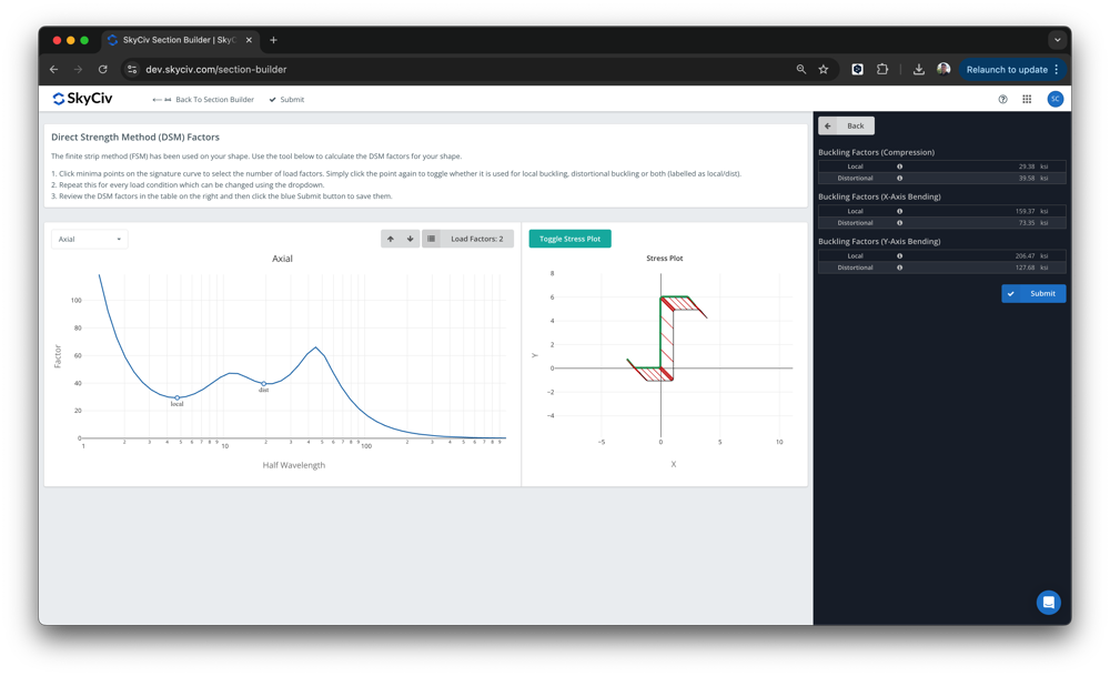
El software está construido sobre SkyCiv Section Builder, debajo Diseño – Formado en frío. Los mínimos de pandeo local y distorsional se detectarán automáticamente., sin embargo, los usuarios pueden anular estos valores.. Una vez enviado, Estos factores luego se utilizarán en el diseño del SkyCiv AISI. (2016) y AS4600 (2018) módulos de diseño integrados.
In SkyCiv elastic buckling analysis module, there are some important hypotheses and considerations that we clarify here. Exploraremos estos a continuación:
Mesh of elements
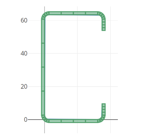
The mesh of the elements is produced automatically and can be viewed in the right chart, the fillets are split into 4 elementos, and the straight line into 4 elements too.
Analysis lengths
The lengths used to perform the Finite Strip analysis are defined by default as a logarithmic space from 0 to 10^3 in the imperial unit system and from 0 to 10^3.5 in the metric system.
Load conditions
We calculate the signature curve for 5 different load conditions:
- Axial load
- Bending moment in X axis, positivo
- Bending moment in X axis, negativo
- Bending moment in Y axis, positivo
- Bending moment in Y axis, negativo
Condiciones de borde
The analysis is performed assuming the model is pinned and free to warp at both ends.
Signature Curve
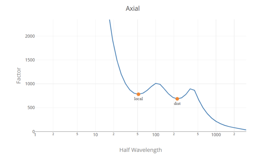
The signature curve is constructed using the conventional Finite Strip Method, Fy is normalized (Fy = 1) so the load factors are presented in pressure units (MPa or ksi according to the unit system).
Load Factor Selection
Generalmente, the load factors are the local minimum points in the signature curve, el primero representa el factor de carga crítico para pandeo local y el segundo representa el factor de carga crítico para pandeo distorsional.. Determinar el factor de carga global a partir de la curva de firma es una tarea difícil ya que no existe un punto mínimo local en la curva de firma.. Entonces, la solución más adecuada es utilizar los factores de carga de pandeo local y distorsional procedentes de un análisis de Banda Finita y el factor de pandeo global utilizando las fórmulas clásicas.
Usamos un algoritmo para encontrar y clasificar los factores de carga en la curva de firma.. sin embargo, this does not ensure a correct classification in all the cases, and this does not replace the engineering judgment, Animamos al usuario a revisar los valores y modificarlos si es necesario antes de enviarlos..
Referencias
- Especificación norteamericana para el diseño de miembros estructurales de acero conformados en frío, 2016 Edición, Instituto Americano del Hierro y el Acero.
- Método de fuerza directa (DSM) Guía de diseño, 2006, Comité de Especificaciones para el diseño de miembros estructurales de acero conformados en frío.
- Análisis de pandeo de miembros de acero conformados en frío usando CUFSM.: Métodos de tiras finitas convencionales y restringidos., B.W.. Schäfer y S.. adany, 2006, 18ª Conferencia Internacional de Especialidad en Estructuras de Acero Conformadas en Frío.

