NS Operasyonlar sağ araç çubuğundaki grup, kırpma için geometri düzenleme araçlarını içerir, uzanan, bölme, katılmak, ölçeklendirme, ve mülk eşleştirme.
Çoğu işlem seçilen geometri üzerinde çalışır. Etkin olanı kullan Hindistan konumlarına girin hassas seçimler ve hedef noktalar için ayarlar.
Operasyonlar
İşlem araçları sağ çubukta açılır yığınlar halinde gruplandırılmıştır. Geçerli aracı etkinleştirmek için kategori düğmesine tıklayın, veya aynı yığından başka bir araç seçmek için mini araç çubuğunu açın.
Özellikleri Eşleştir
Stil ve nitelik özelliklerini bir nesneden diğerine kopyalama
NS Özellikleri Eşleştir komut, kaynak nesnedeki özellikleri uyumlu hedef nesnelere uygular.
Adım adım
- 1Özelliklerinin kopyalanacağı kaynak nesneyi seçin.
- 2Tıklayın Özellikleri Eşleştir fırça modunu etkinleştirmek için.
- 3Özellikleri anında uygulamak için uyumlu hedef öğelere tıklayın.
- 4Tıklamaya devam et, veya birden fazla hedef için çit veya pencere seçimini kullanın.
- 5Basın ESC fırça modundan çıkmak için.
Aşağıdaki açılır pencere, aşağıdaki iki gerekli girişle birlikte gösterilecektir.: Özellikleri Eşleştir, renk gibi görsel özellikleri kopyalar, çizgi ağırlığı, çizgi stili, ve katman. Yalnızca hedef nesne türüyle uyumlu özellikler uygulanır.
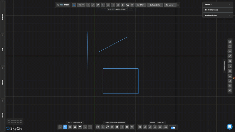
Uzatmak
Seçilen köşeleri geçiş penceresi veya kement kullanarak taşıyın
Uzatmak Bağlı geometri etrafındaki topolojiyi korurken köşeleri hareket ettirir.
[__INSERT_IMAGE__]
Adım adım
- 1Etkinleştir Uzatmak.
- 2Sağdan sola geçiş penceresi veya kement içeren köşeleri seçin.
- 3Serbest bir hareket için ortadaki tutamacı sürükleyin, veya kısıtlı bir hareket için X/Y tutamaçları.
Aşağıdaki açılır pencere, aşağıdaki iki gerekli girişle birlikte gösterilecektir.: Yalnızca geçiş seçimi içindeki köşeler taşınır; Seçimin dışındaki köşelere bağlı çizgiler, bağlantıyı sürdürmek için uzatılır.
Çizgiyi Uzat
Bir çizgiyi hedef çizgiye veya noktaya ulaşana kadar uzatın
Çizgiyi Uzat hedef sınırı karşılamak için seçilen çizgiyi uzatır. Çizgi, seçilen hedefle kesişene kadar mevcut yönü boyunca uzatılır.
Adım adım
- 1Etkinleştir Çizgiyi Uzat.
- 2Uzatmak için çizgiye tıklayın (büyümek istediğin sona doğru).
- 3Uzatılacak hedef çizgiye veya noktaya tıklayın.
Aşağıdaki açılır pencere, aşağıdaki iki gerekli girişle birlikte gösterilecektir.: Uzatılmasını istediğiniz satırın sonuna yakın bir yere tıklayın – araç en yakın uç noktadan hedefe doğru uzanır.
Kırpma
Kesici kenarlarla tanımlanan çizgi veya yay parçalarını kaldırın
Kırpma kesici kenarlar olarak diğer geometriyi kullanarak çizgilerin veya yayların bölümlerini kaldırır. İlk önce kesici kenarları seçin, onları onayla, ardından kaldırmak istediğiniz bölümleri tıklayın veya çerçeveleyin.
Adım adım
- 1Etkinleştir Kırpma.
- 2Kesici kenar geometrisini seçin (çizgiler, SkyCiv Bölüm Oluşturucu bir delik eklemenizi sağlar, daireler).
- 3Basın seçin veya Boşluk çubuğu kesme kenarlarını onaylamak için.
- 4Kaldırılacak bölümleri tıklayın veya çerçeveleyin.
Aşağıdaki açılır pencere, aşağıdaki iki gerekli girişle birlikte gösterilecektir.: Kesici kenarları onayladıktan sonra birden fazla parçayı aynı anda kırpmak için bir pencere veya çit seçimini kullanabilirsiniz.
Çizgiyi Parçalara Böl
Bir çizgiyi N eşit parçaya bölme
Çizgiyi Parçalara Böl tek bir satırı belirli sayıda eşit uzunlukta parçalara böler. Ortaya çıkan her bölüm bağımsız bir çizgi öğesidir.
Adım adım
- 1Aracı etkinleştirin.
- 2Bölmek için çizgiye tıklayın.
- 3Bölme sayısını girin ve tuşuna basın. seçin.
Aşağıdaki açılır pencere, aşağıdaki iki gerekli girişle birlikte gösterilecektir.: Bir kiriş boyunca eşit aralıklı destek noktaları oluşturmak veya yük dağıtım analizi için bir açıklığı bölmek için kullanışlıdır.
Satırı Aralığa Göre Böl
Bir çizgiyi tekrarlanan sabit uzunluklu aralıklara bölme
Satırı Aralığa Göre Böl bir çizgiyi belirli bir sabit uzunluktaki parçalara böler. Eğer çizgi uzunluğu aralığın tam katı değilse sonda bir kalan parça oluşturulur..
Adım adım
- 1Aracı etkinleştirin.
- 2Bölmek için çizgiye tıklayın.
- 3Aralık uzunluğunu girin ve tuşuna basın. seçin.
Aşağıdaki açılır pencere, aşağıdaki iki gerekli girişle birlikte gösterilecektir.: Bilinen bir aralıkta sürekli bir eleman boyunca eşit aralıklı ara düğümler oluşturmak için bunu kullanın (Örneğin., her 500 kiriş düzeni için mm).
Çizgi Boyunca Konuma Göre Böl
Bir çizgiyi uç noktalarından birinden uzaklık mesafesinde bölme
Konuma Göre Böl seçilen çizginin bir ucundan ölçülen mesafeye bir kırılma noktası ekler, bu ofset konumunda iki ayrı segment oluşturmak.
Adım adım
- 1Aracı etkinleştirin.
- 2Bir satırı tıklayın (tıklama konumu hangi uç noktadan ölçüleceğini belirler).
- 3Ofset mesafesini girin ve tuşuna basın. seçin.
Aşağıdaki açılır pencere, aşağıdaki iki gerekli girişle birlikte gösterilecektir.: Ölçmek istediğiniz uç noktanın yakınına tıklayın – takım, ofset mesafesi için referans olarak en yakın uç noktayı kullanır.
Kavşaklarda Ayrık Çizgiler
Seçilen tüm çizgileri kesişme noktalarında otomatik olarak böl
Kavşaklarda Ayrık Çizgiler seçilen çizgilerin birbirini kestiği tüm noktaları bulur ve her kesişim noktasına bölünmüş düğümler ekler. Hiçbir giriş değeri gerekli değildir – işlem tamamen otomatiktir.
Adım adım
- 1İşlenecek satırları seçin.
- 2Tıklayın Kavşaklarda Ayrık Çizgiler.
- 3Tüm geçiş kavşakları otomatik olarak algılanır ve bölünür.
Aşağıdaki açılır pencere, aşağıdaki iki gerekli girişle birlikte gösterilecektir.: Kullanmadan önce bunu çalıştırın Ortak Seçimi veya topolojiye bağlı işlemlerin gerçekleştirilmesi – kesişen çizgilerin gerçek düğüm noktalarını paylaşmasını sağlar.
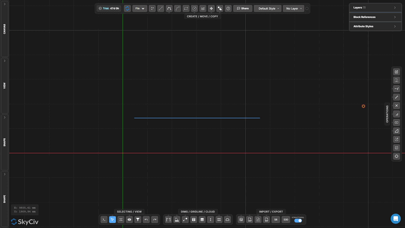
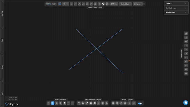
Hedefi Böl
Ayrı ayırıcı geometriyi kullanarak önceden seçilmiş hedef nesneleri bölün
Hedefi Böl bölünecek nesneleri ilk olarak işaretlediğiniz iki aşamalı bir bölmedir (hedefler), daha sonra bunları bölecek geometriyi ayrı ayrı seçin (bölücüler). Yalnızca hedef nesneler kesilir.
[__INSERT_IMAGE__]
Adım adım
- 1Bölünecek hedef nesneleri önceden seçin.
- 2Etkinleştir Hedefi Böl.
- 3Ayırıcı geometrisini seçin.
- 4Basın seçin ayırıcılarla kavşaklardaki hedefleri bölmek için.
Aşağıdaki açılır pencere, aşağıdaki iki gerekli girişle birlikte gösterilecektir.: Belirli çizgileri bir kesici kenarla bölmek istediğinizde ancak kesme geometrisini olduğu gibi korumanız gerektiğinde Bölme Hedefi'ni kullanın. (Trim'in aksine, bu aynı zamanda kesiciyi de değiştirir).
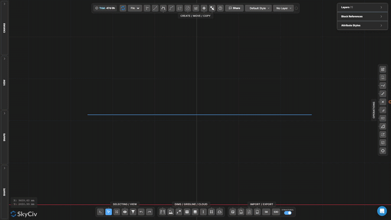
Örtüşmelerde Böl
Çakışan eşdoğrusal çizgi bölümlerini tespit edin ve ayırın
Örtüşmelerde Böl seçili çizgilerin eşdoğrusal olan ve birbiriyle örtüşen bölümlerini bulur, daha sonra bunları böler, böylece örtüşen bölgeler ayrık hale gelir, ayrı ayrı seçilebilir geometri.
[__INSERT_IMAGE__]
Adım adım
- 1Üst üste binen eşdoğrusal kısımlara sahip olabilecek çizgileri seçin.
- 2Tıklayın Örtüşmelerde Böl.
- 3Çakışan bölgeler ayrı segmentlere bölünür.
Aşağıdaki açılır pencere, aşağıdaki iki gerekli girişle birlikte gösterilecektir.: Şununla birleştir: Kopyaları Seç içe aktarılan DXF dosyalarındaki gereksiz örtüşen satırları belirlemek ve kaldırmak için.
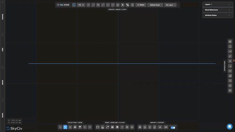
Çoklu Çizgiyi Patlat
Bir sürekli çizgiyi bağımsız çizgi veya yay bölümlerine ayırın
Çoklu Çizgiyi Patlat çok bölümlü bir çoklu çizgiyi bireysel bağımsız bölümlere ayırır. Düzenlemeniz gerektiğinde kullanışlıdır, silmek, veya işlemleri sürekli çizginin yalnızca bir kısmına uygulayın.
[__INSERT_IMAGE__]
Adım adım
- 1Patlatılacak çoklu çizgiyi seçin.
- 2Tıklayın Çoklu Çizgiyi Patlat.
- 3Her segment ayrı ayrı seçilebilir ve düzenlenebilir hale gelir.
Aşağıdaki açılır pencere, aşağıdaki iki gerekli girişle birlikte gösterilecektir.: Ters işlem Çizgileri ve Yayları Birleştirin, bağlı bölümleri tekrar tek bir sürekli çizgide birleştiren.
Çizgileri ve Yayları Birleştirin
Bağlantılı çizgileri ve yayları tek bir sürekli çizgide birleştirin
Çizgileri ve Yayları Birleştirin bağlantılı segmentlerden oluşan bir zinciri tek bir sürekli çoklu çizgi nesnesinde birleştirir. Çizgiler ve yayların birleştirilebilmesi için uç noktaları paylaşması gerekir.
Adım adım
- 1Uç noktaları paylaşan çizgileri ve yayları seçin.
- 2Tıklayın Çizgileri ve Yayları Birleştirin.
- 3Bağlı bölümler tek bir sürekli çizgi halinde birleşir.
Aşağıdaki açılır pencere, aşağıdaki iki gerekli girişle birlikte gösterilecektir.: Seçilen tüm segmentler tek bir sürekli zincir oluşturmalıdır. Segmentlerde boşluklar varsa, kullanım Satır Uçlarına Yasla ve uç noktaları kapatmak için önce Noktayı Taşı aracını kullanın.
Fileto Oluştur
İki çizgi arasında keskin bir köşeyi bir yay ile yuvarlayın
Fileto Oluştur iki çizgi arasındaki keskin köşeyi belirli bir yarıçaptaki teğet yay ile değiştirir. Orijinal çizgi uçları yaya uyum sağlayacak şekilde kesilir.
Adım adım
- 1Etkinleştir Fileto Oluştur.
- 2İletişim kutusunda radyus yarıçapını ayarlayın.
- 3Köşeyi tıklayın (kesişim alanı) uygulanacak iki satırdan.
Aşağıdaki açılır pencere, aşağıdaki iki gerekli girişle birlikte gösterilecektir.: Yarıçap, köşeden itibaren her iki çizginin uzunluğuna sığacak kadar küçük olmalıdır. Onaylamadan önce canlı bir önizleme gösterilir.
Pah Oluştur
Bir köşede düz bir eğimli kesim oluşturun
Pah Oluştur iki çizgi arasındaki bir köşe boyunca düz bir çapraz eğim keser. Her çizginin köşeden ne kadar geride kesileceğini kontrol etmek için pah mesafesini ayarlayın.
Adım adım
- 1Etkinleştir Pah Oluştur.
- 2İletişim kutusunda pah mesafesini ayarlayın.
- 3Pah uygulamak için köşe geometrisine tıklayın.
Aşağıdaki açılır pencere, aşağıdaki iki gerekli girişle birlikte gösterilecektir.: Pah varsayılan olarak her iki hattan eşit şekilde keser. Asimetrik eğim için (her iki tarafta farklı mesafeler), iletişim kutusunda iki ayrı pah değeri ayarlayın.
Nesneleri Ölçeklendir
Seçilen geometriyi pivot noktasından bir faktöre göre ölçeklendirin
Nesneleri Ölçeklendir seçilen geometriyi seçilen pivot noktasına göre tekdüze bir ölçek faktörüne göre yeniden boyutlandırır. Bir iletişim kutusu, ek açıklamaların olup olmayacağını seçmenizi sağlar. (boyutlar, Metin, Bu yeni yazı dizisinde, kılavuz çizgileri, tablolar) aynı zamanda ölçeklendirilmiş.
Adım adım
- 1Ölçeklenecek nesneleri seçin.
- 2Tıklayın Nesneleri Ölçeklendir ve iletişim kutusundaki açıklama ölçeği seçeneklerini yapılandırın.
- 3Ölçek pivotunu ayarlamak için tuvali tıklayın (Menşei) nokta.
- 4Ölçek faktörünü yazın ve tuşuna basın seçin (1.0 = değişiklik yok, 0.5 = yarım, 2.0 = çift).
Aşağıdaki açılır pencere, aşağıdaki iki gerekli girişle birlikte gösterilecektir.: Ek açıklama boyutlarının olup olmadığını kontrol etmek için Ölçek Seçenekleri iletişim kutusunu kullanın. (boyutlar, Metin, Bu yeni yazı dizisinde, tablolar) geometriyle ölçeklendirin veya mevcut boyutlarında kalın.
Ölçek Çerçevesi
Görünür bir çerçeveye sahip kalıcı bir yerel ölçek bölgesi oluşturun
Ölçek Çerçevesi ilişkili ölçek faktörüne sahip kalıcı bir dikdörtgen bölge oluşturur. Çerçevenin içine çizilen veya yerleştirilen geometri o yerel ölçekte oluşturulur. Farklı bir çizim ölçeğindeki detay açıklamaları için kullanışlıdır.
[__INSERT_IMAGE__]
Adım adım
- 1Etkinleştir Ölçek Çerçevesi.
- 2İlk köşeye tıklayın, daha sonra çerçeveyi tanımlamak için karşı köşe.
- 3Girişe ölçek faktörünü yazın ve tuşuna basın. ESC uygulamak.
Aşağıdaki açılır pencere, aşağıdaki iki gerekli girişle birlikte gösterilecektir.: Çerçeve oluşturulduktan sonra tuvalde kalır. Artık ihtiyaç duyulmadığında seçin ve silin. Çerçeve seçiliyken ölçek girişi daha sonra düzenleme için kullanılabilir durumda kalır.
Kaynağı Güncelle
Çizim koordinat orijinini taşı (0,0) yeni bir yere
Kaynağı Güncelle çizimin referans koordinat sisteminin yerini değiştirir. Tüm koordinat değerleri (X, Y) tuvalde görüntülenen ve dışa aktarılan veriler yeni orijine göre yeniden hesaplanır.
[__INSERT_IMAGE__]
Adım adım
- 1Etkinleştir Kaynağı Güncelle.
- 2Kanvastaki yeni başlangıç konumuna tıklayın.
- 3Koordinat okumaları yeniye göre hemen güncellenir (0,0) nokta.
Aşağıdaki açılır pencere, aşağıdaki iki gerekli girişle birlikte gösterilecektir.: Kesin yeni bir başlangıç noktası için mevcut bir düğüme yapışın. Yapısal çizimler için, Koordinatları proje referans ızgarasıyla hizalamak için bilinen bir sütuna veya veri kesişimine yaslanın.
Kilidini aç
Bedava Hesap
Ücretsiz bir hesap için kaydolun ve güçlü analize erişin + tasarım yazılımı:
✓ Güçlü Analiz Yazılımı
✓ Erişim 90+ Tasarım Araçları
✓ EKSENLER, GİBİ, İÇİNDE, NBCC yük jeneratörü
✓ Çelik, Kereste, Somut, Bu malzemelerin, ihtiyacınız olan yapıyı modellemek için üyeleri ve plakaları temsil eden bölümlere atanması gerekir.