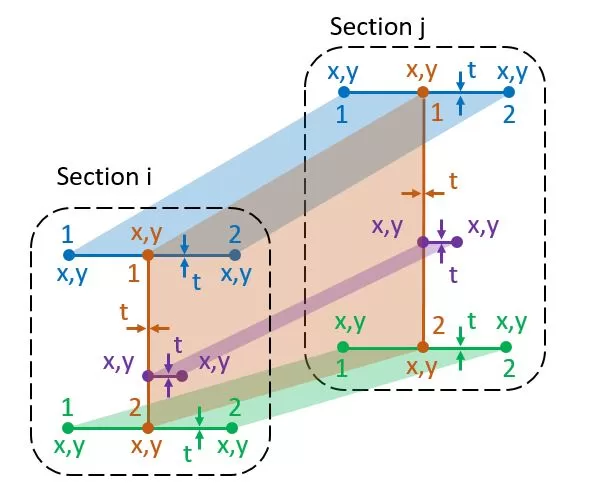
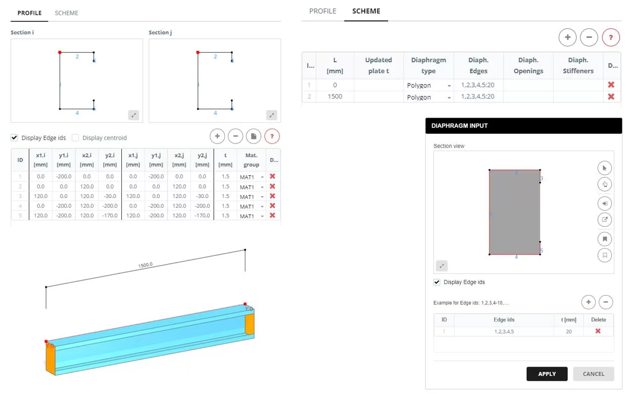
Her üyenin bir başlangıç bölümü i ve bir bitiş bölümü j vardır.. Bir bölüm iki düğüm tarafından tanımlanan çizgilerden oluşur, x,kesit düzleminde y. Her çizgi farklı bir t kalınlığına sahiptir ve belirli bir malzeme grubuna aittir.. x için referans noktası,y koordinatları her bölüm için uzayda keyfi olarak seçilebilir. Her bölümdeki satır sayısı tutarlı olmalıdır. Tabloya ilişkin veriler manuel olarak girilebilir veya bir Excel sayfasından içe aktarılabilir. bunlara ek olarak, kesit şekilleri kullanıcının bilgisayarında saklanan bir DXF dosyasından içe aktarılabilir.
Güncelleme: Seçilen çizgi grubu için ortak kalınlık değiştirilebilir
Mat'ı Güncelle.: Seçilen hat grubu için ortak malzeme grubu değiştirilebilir
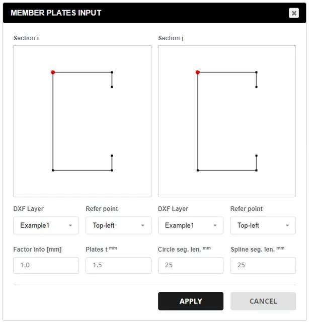
DXF'den veriler.: Bilgisayarınızdan bir DXF dosyası seçin. Bölüm öğeleri için istediğiniz katmanı seçin. Referans noktası, kaynağı belirler. x,Y koordinatlar. Bölüm koordinatlarını milimetreye ölçeklendirmek için faktörü kullanın. Tüm çizgilere varsayılan kalınlık uygulanacaktır, daha sonra değiştirilebilir. Desteklenen DXF varlıkları şunları içerir:: çizgiler, Sürekli çizgiler, Yaylar, ve Spline'lar. Yaylar ve Spline'lar için, segment bölümü tercih edilen ağ boyutuna uyacak şekilde belirtilmiştir.
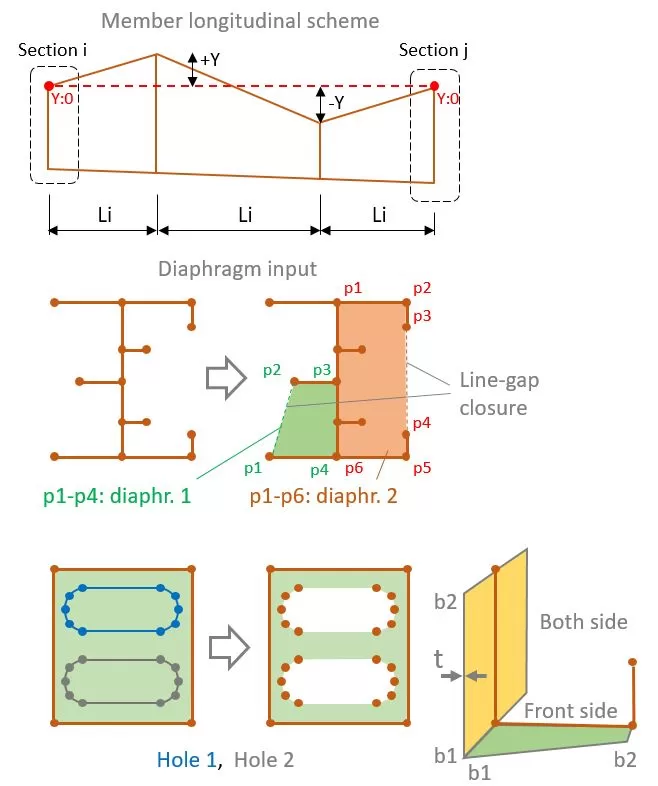
Tüm üye ya tek bir uzunluk L ile ya da bir dizi parça Li ile temsil edilebilir.. Segment sayısından bağımsız olarak, başlangıç ve bitiş kesit çizgileri PROFİL sekmesinde tanımlandığı gibi aynı koordinatlara sahip olacaktır. Her bölümün farklı Y konumu da olabilir.
Her bölüm için burada L eşit değil 0, bir grup plakanın kalınlığı 'Güncellenmiş plaka t sütunu'nda güncellenebilir. seçin 0 plakayı ve değerinden daha büyük bir değeri gizlemek için 0 kalınlığı değiştirmek için (t).
Segment bölümleri için, 'Çokgen' olması durumunda bir diyafram eklenebilir’ tür seçilir. Bir veya daha fazla diyaframı belirtmek için, şekli oluşturan çizgileri seçin. Şekli oluşturmak için yalnızca bir satır aralığı kapatmasına izin verilir.
Delikler diyaframın içine de yerleştirilebilir. Bunu yapmak için, delikleri çevreleyen karşılık gelen çizgileri seçerek delik şekillerini tanımlayın.
Bir diyafram belirtilmişse, daha sonra flanşlar veya takviyeler de ilgili hatları seçilerek tanımlanabilir. Her flanş veya takviyenin bir başlangıç ve bitiş genişliği vardır (b1,b2), kalınlık t, ve malzeme grubu.
Misal
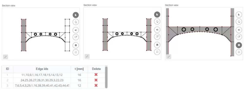
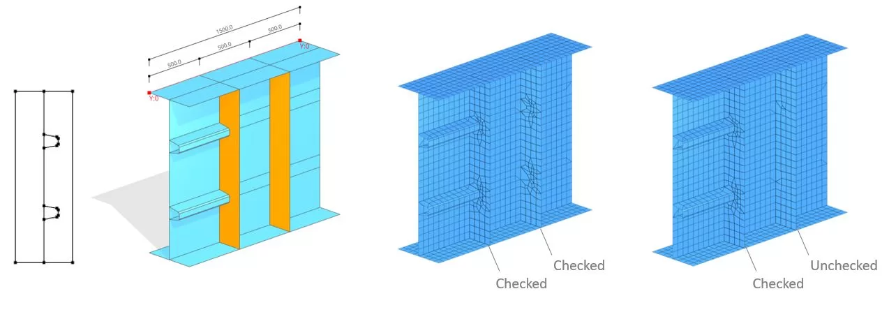
Bir diyafram içindeki kenarları düzenlerken, ağ desenine dahil edilebilirler. Örneğin, boyuna bir takviyenin dikey bir takviyeye bağlandığı bir durum ortaya çıkabilir. Bu tür senaryolarda, 'iç kenarlar’ seçeneği etkinleştirilmelidir. ancak, dikey takviye herhangi bir şeye bağlı değilse, bu seçenek devre dışı bırakılabilir.