
Kesme Bağlantısı nedir?
A shear connection is a joint that transfers shear force between two members without transferring meaningful moment. If a beam carries internal kesme kuvveti, that force passes through the connection into the supporting column as eksensel kuvvet. Shear connections behave as a pin (FFFFFR in SkyCiv Structural 3D), unlike moment bağlantıları, which hold the end rotation.
In AISC 360-16 terms this is a altında da mevcuttur bağlantı: it is assumed to rotate freely and to carry negligible moment. GİBİ 4100:2020 calls the equivalent arrangement simple construction. A semi-rigid joint is a third case, with real but partial rotational stiffness, and it has to be modelled that way rather than treated as simple.
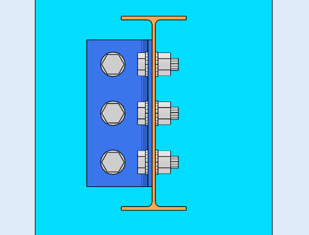
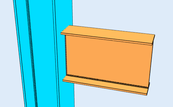
A plate or angle carries the force between the two members. Yukarıdaki örnekte, any downward load on the beam passes into the supporting member through the angle. Because nothing restrains the beam flanges, the joint can rotate, which is what makes it a shear connection rather than a moment connection.
SkyCiv Professional paketi ayrıca çelik içerir are the most common connection in steel framing. Where a frame is braced, the bracing provides the lateral stability, so moment connections are needed only where the frame relies on frame action. That is why most designers reach for a shear connection wherever the analysis allows: they are simpler to fabricate and cheaper to erect.
SkyCiv Connection Design checks shear connections to AISC 360-16 hem ASD'de hem de LRFD'de, ve GİBİ 4100:2020.
Kesme Bağlantı Çeşitleri
Shear connections are named after the component that carries the load and where it sits. Which ones are available depends on the design code and on what the beam frames into, so the lists below are split that way.
I kesitli sütuna kiriş, or beam to beam (AISC 360-16)
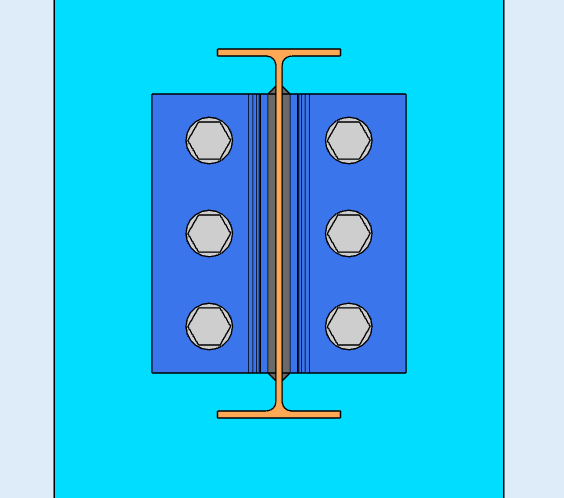
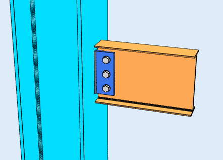
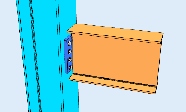
Six configurations, each available framing to the column flange, to the column web, or beam-to-beam through the web:
- Tek Açılı. One L-shaped bracket between the beam web and the support. The lightest option, and the most flexible, so it suits light loads.
- Çift Açılı. Angles on both faces of the beam web. The extra angle roughly doubles the bolt shear planes and makes the connection more forgiving during erection, which is why it is the workhorse for heavier beams.
- Tek Plaka. The shear tab. One plate, shop-welded to the support and bolted to the beam web. Usually the cheapest of the group, because there is one weld line and one bolt group.
- Çift Tabak. Plates on both faces of the web, used where a single plate cannot carry the shear or fit the required bolt group.
- Uç plakası. A plate welded to the beam end and bolted to the support. It needs the beam cut to length accurately, since the plate leaves no adjustment.
- Doğrudan Kaynaklı Ağ. The beam web welded straight to the support, with no intermediate plate or angle. There are no bolts to check, but it needs field welding and gives up the erection tolerance a bolted detail provides.
HSS sütununa kiriş (AISC 360-16)
Framing into a hollow section changes what fits, because there is no flange to bolt to and no access to the far side for a wrench. Five configurations are available:
- Tek Açılı ve Çift Açılı
- Tek Plaka
- Tek WT. A tee cut from a wide flange, its stem welded or bolted to the beam web and its flange to the column face.
- Koltuk Açısı. An angle under the bottom flange carrying the beam in bearing, normally with a top clip for stability. Unlike the web-connected types, this one works off the flange.
GİBİ 4100:2020
The Australian code covers beam-to-I-column and beam-to-beam framing, with four configurations:
- Web Tarafı Plakası, the AS 4100 name for the shear tab.
- Esnek Uç Plakası
- Tek Açılı ve Çift Açılı
GİBİ 4100 coverage is shear only, and does not extend to HSS columns, kanallar, bracing or splices. Those are AISC 360-16.
Yazılım neyi kontrol ediyor??
For a shear connection, the design runs both a detailing pass and a strength pass.
Detailing runs first and catches the geometry: cıvata kenar mesafeleri, cıvata aralığı (adım ve ölçü), takım açıklıkları, and minimum and maximum plate dimensions, artı plakalar arasında çatışma tespiti, cıvatalar ve kaynaklar. A connection that fails here never reaches the solve. That is usually what you want, because the numbers do not matter if the detail cannot be built.
The strength checks then cover bolt shear, cıvata yatağı ve yırtılma, blok kesme kopması, plate yielding and rupture, kaynak boğaz gerilimi, and the local limit states of the supporting member such as web local yielding. Her formül, tasarım kontrolü ve kod referansı tam olarak gösterilir, with the clause numbers from AISC 360-16 veya AS 4100:2020, böylece hesaplamaya güvenmek yerine takip edebilirsiniz.
For the fastener side of this, ilgili belgelere bakın cıvatalar ve kaynaklar.
Kesme ve Moment Bağlantısı arasındaki fark nedir??
A shear connection transfers shear only. A moment connection also transfers bending. Think of it as a menteşe: a shear connection lets the beam end rotate, a moment connection holds it.
The distinction is a decision about the analysis model, not only about the detail. A shear tab designed as simple has to be flexible enough to actually rotate, and a moment connection has to be stiff enough to justify the fixity the frame model assumed.
| Kesme Bağlantısı | Moment Bağlantısı | |
|---|---|---|
| Aktarılan Kuvvetler | Sadece Kesme | Kesme ve Moment |
| Alternatif isimler | Sabitlendi, Menteşe, Basit | Sert, Sabit, Anı dirençli |
| AISC 360-16 terim | Basit bağlantı | FR veya PR moment bağlantısı |
| Rotasyon | Döndürmeye İzin Verir | Restrains Rotation |
| Yazılım Sabitleme Kodu | FFFFFR | FFFFFF |
SkyCiv Bağlantı Tasarım Yazılımı
Yukarıdaki modeller ve kontroller SkyCiv Bağlantı Tasarımı. Üzerini kapsıyor 80+ önceden yapılandırılmış bağlantı türleri, designs to AISC 360-16 (LRFD & ASD) ve benzeri 4100:2020, ve her formülü gösterir, tam tasarım kontrolü ve kod referansı.
Bağlantıyı 3 boyutlu olarak modelleyebilirsiniz, cıvataları değiştir, yük verilerinizi kaybetmeden kaynaklar veya plakalar, CloudCAD'de 2D detay çizim sayfaları oluşturun, ve Revit'te koordinasyon için 3D geometriyi IFC'ye aktarın, Tekla veya Navisworks.
Tamamen tarayıcıda çalışır, indirmesiz, güncellemeler veya BT kurulumu.
