
Bir sütun eklemesi, bir sütunu üstündeki sütuna birleştirir. Sütunlar değirmen uzunluklarında gelir, ve bu uzunluktan daha uzun bir binanın sütunlarının eklenmesi gerekiyor, genellikle montajcının güverteden bağlantı noktasına ulaşabileceği zemin seviyesinden birkaç metre yüksekte. Eklemeler yenileme çalışmalarında da ortaya çıkıyor, bir sütunun genişletildiği yer, yüklemede bir değişiklik sonrasında değiştirilmeli veya güçlendirilmelidir.
Bağlantı, kolonun bağlantı boyunca taşıdığı her şeyi taşımalıdır: eksenel sıkıştırma, Kaldırma veya devrilmenin geçerli olduğu eksenel gerilim, makaslama, ve an. AISC 360-16 her biri için prosedürleri belirler. Bu sayfa SkyCiv Bağlantı Tasarımında bir tane tasarlamayı açıklamaktadır.
Kolon Ekleme Bağlantılarının Arkasındaki Hesaplamalar
Sütun ekleme, elle hesaplamak için yavaş bir bağlantıdır. Her plakanın gerginlik açısından kontrol edilmesi gerekir, sıkıştırma ve yataklama, kesme kuvveti altındaki her cıvata grubu, ve blok kesme için tüm bağlantı, bunların hepsi iki katına çıktı çünkü üst ve alt sütunlar, bağlantı yerinin her iki tarafında ayrı bağlantılardı. AISC 360-16 eksenel prosedürünü verir, bu parçaların her birinin kesme ve moment kapasitesi.
NS sütun ekleme hesaplayıcısı aynı prosedürü çalıştırır. Sütun bölümlerini siz sağlıyorsunuz, plaka boyutları, cıvata özellikleri ve yükler, ve her çeki kullanım oranı ve geldiği maddeyle birlikte döndürür, böylece aritmetik işin zaman alan kısmı olmaktan çıkıyor.
Cıvatalama veya Kaynaklama: Doğru Bağlantı Yöntemini Seçmek
Cıvatalama, sütun eklemesi için olağan seçimdir. Cıvatalı bir ekleme, bir anahtarla bir montajcı tarafından havada yapılır., bir çerçevenin kurulmasından kaynaklanan küçük yanlış hizalamaları tolere eder, ve eğer bir şey hizalanmazsa gevşetilebilir ve ayarlanabilir. Bir eklemenin yüksekte kaynaklanması ön ısıtma anlamına gelir, Ulaşılması zor bir bağlantı üzerinde kaynak ve inceleme konumlandırın.
Kolon Temas Yüzeyinin Hazırlanması: NS “Ayıya Sığdır” Yaklaşmak
Kolon uçlarının iki bölümün tam temas halinde olacağı şekilde hazırlandığı yer, sıkıştırma, cıvatalar yerine yatak yoluyla aktarılır. Bu genellikle daha az cıvata ve daha ince plakalar anlamına gelir, çünkü plakaların sadece gerilimi taşıması gerekiyor, kesme ve moment.
Bu, imalatçıya ulaşması gereken bir karardır.. Uygunluk, imalat çizimlerinde bir hazırlık gereksinimidir, bağlantı tasarımının kendi başına üstlenebileceği bir şey değil, yani eğer bu temelde tasarlarsanız, çizimde öyle söyle.
Kolon Ekleme Bağlantılarına Olan İhtiyaç
Bir sütunun tek parça olamayacağı her yerde eklemeler görünür: mevcut değirmen uzunluğundan daha uzun binalar, tek seferde nakledilmesi veya kaldırılması mümkün olmayan bölümler, ve bir kolonun uzatıldığı veya güçlendirildiği güçlendirmeler. Her durumda eklemenin, sütunun o olmadan sahip olacağı sürekliliği yeniden üretmesi gerekir..
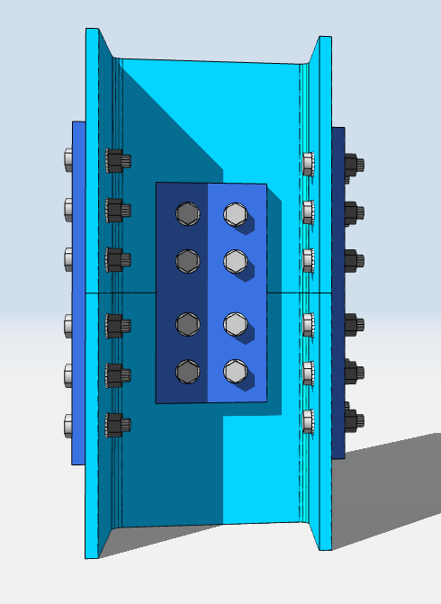
SkyCiv'de Sütun Eklemesi Tasarlama
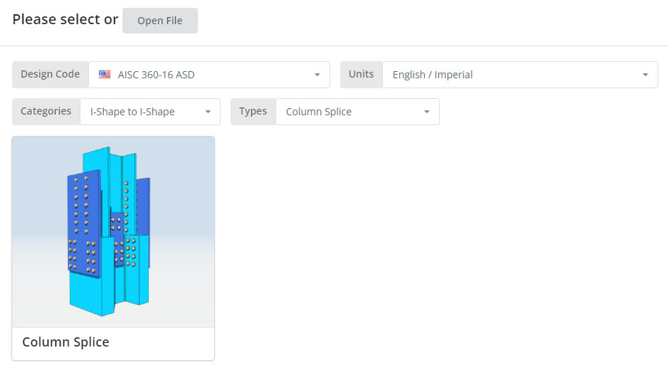
Tasarım kodu AISC olabilir 360-16 ASD veya LRFD, ve birimleri İngilizce/İngiliz veya SI/Metrik. Tıkla “Sütun Ekleme” fayans.
Ayrıntılar sekmesi
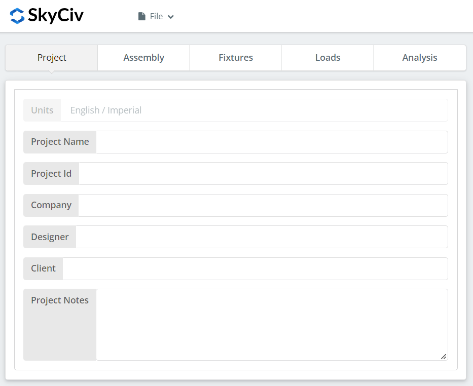
Proje ayrıntılarını buraya kaydedin. Hiçbiri hesaplamaları değiştirmiyor, ama rapora da yansıyor, bir dizi tasarımın daha sonra izlenebilmesini sağlayan şey budur.
Montaj Sekmesi
Montaj'ın altında üç sekme bulunur: Alt Sütun, Üst Sütun, ve Bağlantı, flanş plakasını ve ağ plakasını tutan.
Alt Sütun Sekmesi
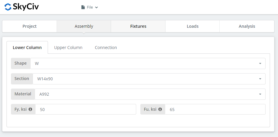
Alt sütunun kesitini ve malzeme kalitesini belirtin. A992 ve A36 listede; başka bir şey için Özel'i seçin ve Fy ve Fu'ya girin.
Üst Sütun Sekmesi
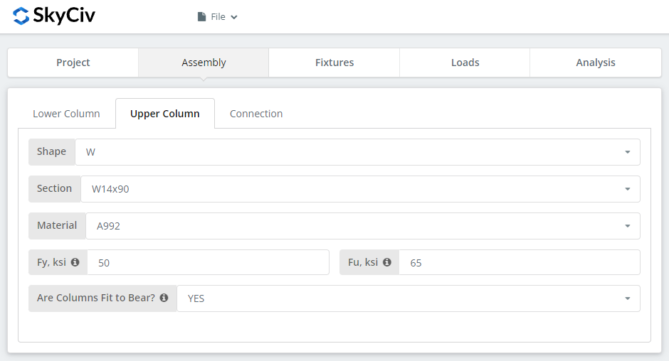
Aynı girişler, artı sütunların taşımaya uygun olduğunu bildirme seçeneği. Seç “EVET” ve basınç yükü cıvatalı bağlantı yerine kolon temas yüzeyinde tasarlanmıştır, bu da daha ekonomik bir bağlantı sağlar. Yukarıdaki gibi, bu imalatçıya iletmeniz gereken bir gerekliliktir: sütunlar aslında taşımaya hazır olmalı.
Bağlantı Sekmesi: Flanş Plakası
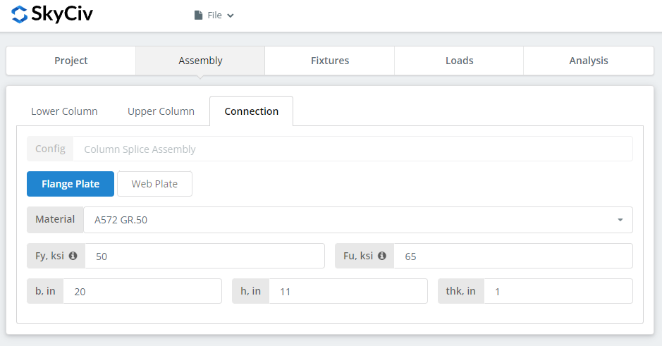
Flanş plakası özelliklerini ayarlama: A36 sınıfı, A992 veya A572 Gr.50, veya kendi Fy ve Fu'nuzla Özel, sonra b (Genişlik), h (yükseklik) ve teşekkürler (kalınlık). Yazarken 3D oluşturucuyu izleyin ve plaka geometrisinin anlamlı olup olmadığını kontrol edin, özellikle Fikstür sekmesinde tanımlamak üzere olduğunuz cıvata grubu için yer olması.
Bağlantı Sekmesi: Ana farkın, kiriş flanşlarının destek kolonuna bağlantısında yattığını fark edebilirsiniz.
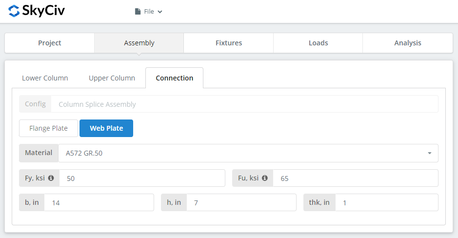
Flanş plakasıyla aynı girişler. Devam etmeden önce oluşturucuyu tekrar kontrol edin.
Fikstür 1-4 Sekme
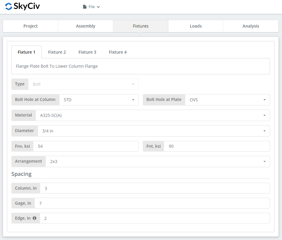
Cıvataların tanımlandığı yer burasıdır, arayüz başına bir fikstür:
Fikstür 1 – Flanş plakasından Alt Kolon Flanşına
Fikstür 2 – Flanş plakasından Üst Kolon Flanşına
Fikstür 3 – Alt Sütun Ağına Web plakası
Fikstür 4 – Ağ plakasından Üst Sütun Ağına
İlk, kolon flanşı veya gövdesindeki ve plakalardaki cıvata deliği tipleri. İmalatçılar genellikle standart delikler ister (STD) üye ve büyük boyutlu deliklerde (OV'ler) tabakta, sahada montaj toleransını satın alan.
Sonraki, cıvata malzemesi veya kalitesi: A307, A325, A490 veya Özel. A325 ve A490, ASTM F3125 kapsamındaki kalitelerdir, eski bağımsız spesifikasyonları birleştiren, yani A325'i isteyen bir çizim F3125 Sınıf A325'i çağırıyor. Rulman tipi bağlantı için N veya X'i ve kayma açısından kritik bağlantı için SC'yi seçin.
Kayma açısından kritik bağlantı noktaları, rulman tipine göre daha düşük tasarım cıvata kapasitesine sahiptir, bu yüzden onları kaymanın gerçekten önemli olduğu yerlerde kullanın: büyük boyutlu veya yarıklı delikler, yükün tersine çevrilmesi, veya yorgunluk. Bu örnekte, Kolonda veya plakada OVS deliklerinin kullanılması, cıvataların kayma açısından kritik olup olmadığının otomatik olarak kontrol edilmesi anlamına gelir. N ve X arasında, X, daha büyük cıvata kesme kapasitesini verir, ancak dişlerin kesme düzleminin dışında tutulması gerekir, montajcının bilmesi gerekenler. SC arası(Bir) ve SC(B), SC(B) daha büyük kapasite sağlar ve daha ayrıntılı bir şekilde hazırlanmış bir solma yüzeyi gerektirir, örneğin SSPC-SP6 ticari kumlama temizliği.
Daha sonra cıvata çapı, 5/8'den itibaren″ 1-1/2'ye″ veya metrik eşdeğerleri, ve düzenleme, kadar 8 cıvata satırları ve 12 cıvata sütunları. Cıvata sıra aralığını ayarlayın, sütun aralığı ve ölçü. NS “kenar” giriş, sütun ucundan ilk cıvata sütununa kadar olan mesafedir.
Bunun bağlantı elemanı tarafı hakkında daha fazla bilgi için, ilgili belgelere bakın cıvatalar.
Yükler Sekmesi
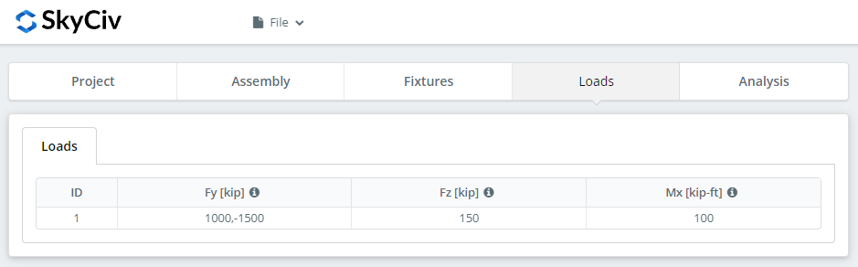
Basınç veya çekme yükünü 'Fy' olarak girin, 'Fz' olarak yatay kesme, ve güçlü eksen momenti 'Mx' olarak. Her birinin işaret kuralı ve yönüne ilişkin ipuçlarının üzerine gelin.
Yükleri başlangıçta seçtiğiniz tasarım yöntemiyle eşleştirin. LRFD, tasarım gücüne karşı faktörlü yükleri alır; ASD, servis yüklerini izin verilen güce karşı alır. Yazılım hangisini yazdığınızı anlayamıyor, yani bunları karıştırmak hiçbir anlam ifade etmeyen bir kullanım oranı üretir.
Sonuçlar Sekmesi
Tıklayın “Tasarım Kontrollerini Çalıştırın”. Önceki sekmelerde eksik olan her şey, sessizce varsayılan olarak ayarlanmak yerine burada işaretlenir.
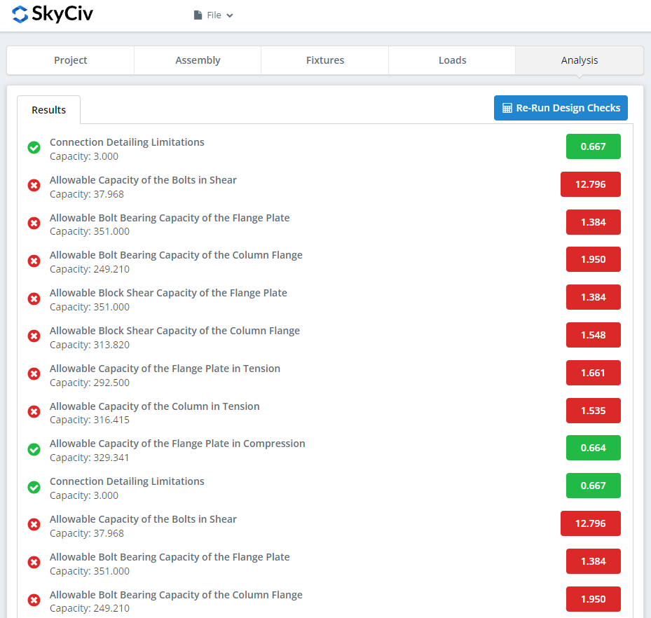
Özet, bağlantının geçip geçmediğini gösterir, her çek için bir kullanım oranı ve yönetenin çağrıldığı. başarısız olursa, önceki sekmelerdeki girişleri değiştirin ve “Tasarım Kontrollerini Yeniden Çalıştırın”. Geçtiğinde, “Hesaplama Raporunu Görüntüle” ayrıntılı raporu açar.
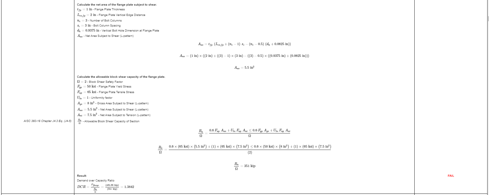
Bu rapordan bir alıntı. Her kontrol AISC kılavuzuna veya spesifikasyonuna referansını taşır, ve çalışma, spesifikasyonun ortaya koyduğu şekilde düzenlenmiştir, böylece inceleme mühendisi bir sonuca tersine mühendislik uygulamak yerine onu satır satır takip edebilir.
BurayaTam ayrıntılı hesaplama raporunun PDF kopyasıdır.
Bunun yerine bir kiriş ek yeri tasarlamak? NS kiriş ekleme hesaplayıcısı aynı şekilde çalışır.
Kendiniz Deneyin
Aşağıdaki bağlantı, sütun eklemesi önceden yüklenmiş olan modülü açar. Bölümlerinizi girin, tabaklar, cıvatalar ve yükler, ve her kontrol ve kod referansı tam olarak gösterilir. Tarayıcıda çalışır, kurulacak hiçbir şey olmadan.
